Adaptive Feedback Control Loop for Martian Habitats Using Additive Manufacturing and Hyper-Inflatables - Wsimg.com
←
→
Page content transcription
If your browser does not render page correctly, please read the page content below
Adaptive Feedback Control Loop for
       Martian Habitats Using Additive
      Manufacturing and Hyper-Inflatables
                      System Design Specification
                     UASE 691/692: Capstone I & II

                             Michael Tuttle

                            Date: 2020-12-21

                              Table 1: Change Log

Date         Draft                                  Changes
2020-11-13   0.1                                    Initial Draft
2020-12-03   0.2                                    Rough Draft Submission
2020-12-21   0.3                                    Final Draft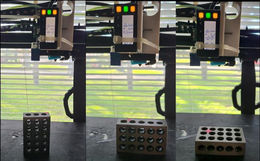
System Design Specification

Table of Contents
1     Introduction ............................................................................................................................. 5
    1.1     Purpose............................................................................................................................. 5
    1.2     System Goals and Objectives ........................................................................................... 5
    1.3     System Scope .................................................................................................................... 5
2     Design Considerations ............................................................................................................ 6
    2.1     Design Model ................................................................................................................... 6
    2.2     Assumptions and Dependencies ....................................................................................... 7
    2.3     Constraints ....................................................................................................................... 7
      2.3.1        CNC Machine............................................................................................................ 7
      2.3.2        Inflation ..................................................................................................................... 7
3     System Architecture ................................................................................................................ 8
    3.1     Hardware Architecture .................................................................................................... 8
      3.1.1        CNC Machine............................................................................................................ 8
      3.1.2        Laser Gauge .............................................................................................................. 9
      3.1.3        ADC........................................................................................................................... 9
      3.1.4        Host Controller ......................................................................................................... 9
    3.2     Software Architecture .................................................................................................. 12
    3.3     System-to-System Interfaces ........................................................................................... 13
4     Mechanical Design................................................................................................................ 14
    4.1     CNC ................................................................................................................................ 16
    4.2     Laser ............................................................................................................................... 16
    4.3     Balloon ........................................................................................................................... 17
    4.4     Stocking Cover ............................................................................................................... 18
    4.5     Dial Indicator ................................................................................................................. 18
5     Electronic Hardware Design ................................................................................................. 19
    5.1     P1-01AC PSU................................................................................................................. 19
    5.2     P1AM-100 ...................................................................................................................... 19
    5.4     Banner L-Gage LE-250 .................................................................................................. 20
6     Software Design .................................................................................................................... 21
    6.1     Prepared Toolpath ......................................................................................................... 22
    6.2     Host Controller .............................................................................................................. 24
      6.2.1        Input ........................................................................................................................ 24
      6.2.2        GCODE ................................................................................................................... 24
      6.2.3        Laser Gauge Controller .......................................................................................... 24
      6.2.4        CNC Machine.......................................................................................................... 24
      6.2.5        Laser Vertical Offset from Tool Tip ........................................................................ 25
      6.2.6        Laser Lateral Offset ................................................................................................ 25
      6.2.7        Laser Vertical Offset from Tool Tip ........................................................................ 25
      6.2.8        Operations............................................................................................................... 25
      6.2.9        Output GCODE ....................................................................................................... 25
                                                                        2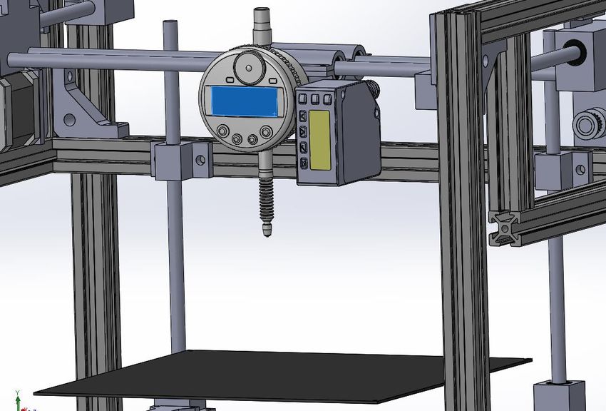
System Design Specification

      6.2.10 Controller Augmentation ........................................................................................ 25
      6.2.11 Input ........................................................................................................................ 26
      6.2.12 Output ..................................................................................................................... 26
7     Verification and Validation Test Plan................................................................................... 26
    7.1     Verification Plan ............................................................................................................ 27
    7.2     Validation Plan .............................................................................................................. 27
    7.3     Traceability Matrix ........................................................................................................ 27
8     External Dissemination Opportunities .................................................................................. 27
9     References ............................................................................................................................. 29
10    Appendix 1 ............................................................................................................................ 32
    10.1       Validation Test #1 ...................................................................................................... 32
    10.2       Validation Test #2 ...................................................................................................... 33
    10.3       Validation Test #3 ...................................................................................................... 34
11    Appendix 2 ............................................................................................................................ 41

Table of Figures
Figure 1 Inflated Binishell with Concrete Cladding by Hedmond, S., 2017, retrieved from
https://www.constructionjunkie.com/blog/tag/benefits+of+binishells ........................................... 6
Figure 2 Dial Indicator Used for Distance Displacement .............................................................. 8
Figure 3 CNC Controller Internal Logics and Controls.................................................................. 9
Figure 4 Example of Coordinate Commands................................................................................ 10
Figure 5 Operations Flow Between Subsystems .......................................................................... 10
Figure 6 CNC Machine Equipped with Dial Indicator and Laser Gauge ..................................... 11
Figure 7 CNC Laser Displace Infographic ................................................................................... 11
Figure 8 CNC Laser Displacement ............................................................................................... 11
Figure 9 Automation Direct Laser Subsystem .............................................................................. 12
Figure 10 Dynamic Software Adjustment Flowchart ................................................................... 13
Figure 11 System of System Data Flow ....................................................................................... 14
Figure 12 9-DOF Kuka KR-240-R3100 Ultra K, by Reddot, 2020, from https://www.red-
dot.org/project/kuka-kr-quantec-210-r2700-45875 ...................................................................... 15
Figure 13 Low-Resolution Toolpath Simulation emulating undercuts......................................... 15
Figure 14 CNC Gantry with Mock Inflated Balloon ................................................................... 16
Figure 15 Banner L-Gage LE-250 3D Rendering......................................................................... 17
Figure 16 Custom Airbladder Dome (Deflated) ........................................................................... 17
Figure 17 Inflated Bladder with Stocking ..................................................................................... 18
Figure 18 Automation Direct Laser Subassembly, by Automation Direct,2020e, retrieved from
https://ftp.automationdirect.com/support/drawings/arduino.zip ................................................... 19
Figure 19 Wiring Diagram of Laser Gauge and LE-250 .............................................................. 20
Figure 20 L-Gage Banner Speed Settings, by Banner Engineering Corp., 2020b, retrieved from
https://info.bannerengineering.com/cs/groups/public/documents/literature/175094.pdf ............. 21
Figure 21 Automation Direct Laser Subassembly Electrically Wired.......................................... 21
Figure 22 High Level Software to Software Flow ........................................................................ 22
Figure 23 Cartesian Coordinate System with Introduced Pauses ................................................. 23

                                                                      3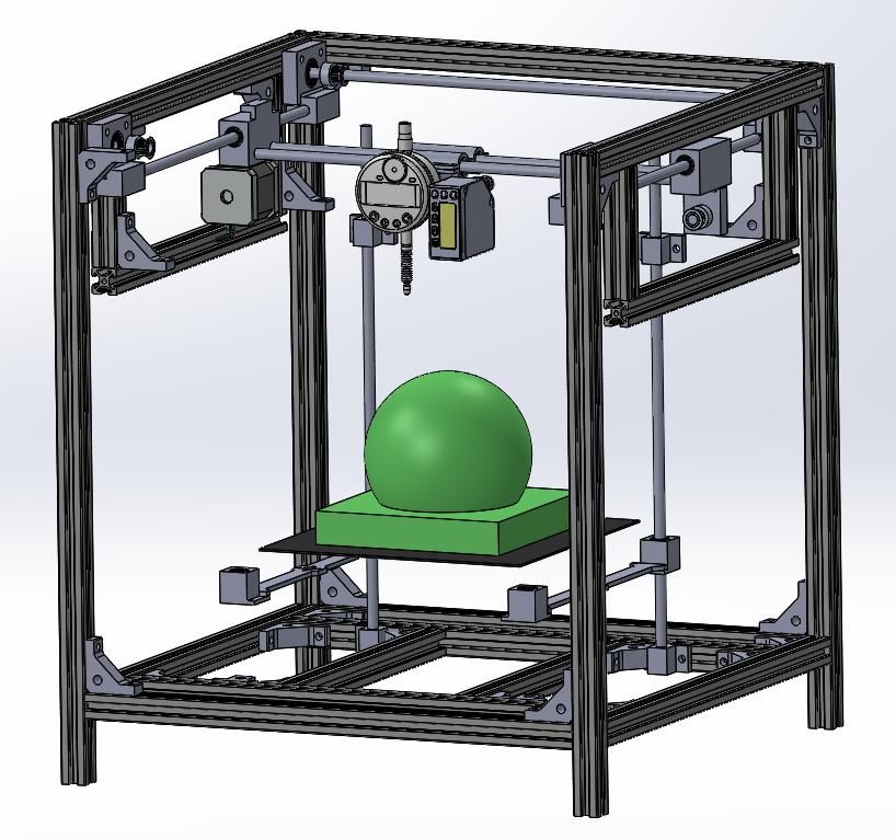
System Design Specification

Figure 24 Simulated Toolpath In X+ Direction ............................................................................ 23
Figure 25 GUI Of Host Controller Software ................................................................................ 24
Figure 26 Example of Digital Laser Code Conversion ................................................................. 26
Figure 27 Calibration Piece for Laser Gauge Software ................................................................ 33
Figure 28 Three Scans Cycles -0.002mm Dev. ............................................................................ 34
Figure 29 Example of Toolpath and Recorded Values ................................................................. 35
Figure 30 Top View of Recorded Values ..................................................................................... 36
Figure 31 Example of Height Keeping Over Geometry ............................................................... 37
Figure 32 Example of Gauge Value of CNC Bed......................................................................... 38

Table 1: Change Log ....................................................................................................................... 1
Table 2: Laser Distance Formula Creation/Accuracy ................................................................... 33
Table 3: Repeatability Test ........................................................................................................... 34
Table 4: Digitizing ........................................................................................................................ 35
Table 5: Dynamic Adjusting ......................................................................................................... 36
Table 6: Dynamic Compensation.................................................................................................. 38

                                                                      4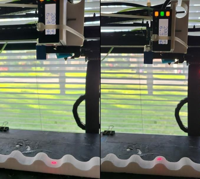
System Design Specification

    1 Introduction
      As humankind sets to inhabit remote planets, a method to manufacture safe, efficient, and
repeatable life supporting habitats is essential. Conventional methods of constructing Earth-
based habitats would likely be inefficient and hazardous due to the cosmic transit times,
economical cost and the atmospheric conditions on remote planets. Adopting the use of
originating planetary resources, such as Martian soil (regolith) paired with a robotic construction
solution, resource efficiency can be increased while reducing human risk.

      During the initial landings on the remote planet, it’s likely conventional heavy construction
such as bulldozers will not be accessible, nor detailed topology maps creating an environment
which is neither smooth nor level. A method to adapt and build upon such surfaces is needed.

1.1 Purpose
      The proposed system introduced within thus report sets to test the feasibility of creating a
supplemental “add-on” feedback loop to additive manufacturing machines (3D printing) that
accounts for any unforeseen anomalies within the workspace or build surface. These anomalies
may include but not limited to rocks, irregular terrain topologies or other unforeseen physical
characteristics that could interfere with an additive manufacturing process.

1.2 System Goals and Objectives
     The fundamental goal of the demonstrated project is to evaluate the effectiveness of
dynamically adjusting for unknown variations in the height, or Z-axis of an additive
manufacturing process. The core objectives that shall be achieved are as followed:

      1. Introduce supplemental measuring device(s) that capture the height difference from a
         tool and support structure being extruded over.

      2. Utilized sensor acts a closed loop device, calculating error(distance) between intended
         surface location and actual measured location.

      3. Dynamically adjust tool position in both positive and negative direction to achieve
         intended geometric location by means of software augmentation.

1.3 System Scope
      This paper will focus on the proposed method of using in-situ resources in conjunction
with an inflatable air bladder(s) to create remote habitats on planets such as Mars (Kading &
Straub, 2015). Such airbladders act as mold or form that emulate a geometry in which regolith is
extruded over and cured leaving a rigid shell for inhabitants (Figure 1). Utilizing airbladders has
many advantages such as conforming to irregular terrains or the ability to compact down in size
and to be reinflated elsewhere. A downfall to using airbladders is that they can easily be
deformed by external factors such as wind, temperature, and external forces. (Dent, 1972)

                                                 5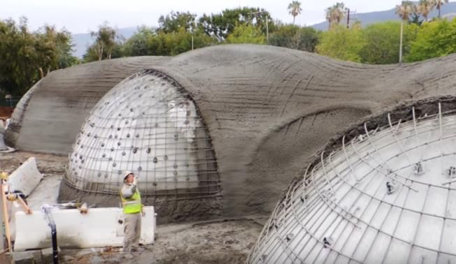
System Design Specification

               Figure 1 Inflated Binishell with Concrete Cladding by Hedmond, S., 2017, retrieved from
                         https://www.constructionjunkie.com/blog/tag/benefits+of+binishells

       The scope of the project is to address these inflation deformations during the extrusion
processes by incorporating a closed loop laser gauging distance device. The proposed gauging
device will talk to a host controller that drives the extrusion process, such as a robotic arm or
gantry system and then dynamically augment the machines motion to compensate for the
inflation deviations.

      This project is limited to a single laser gauge pointed parallel to the tool tip, therefor does
not account for any X axis nor Y axis corrections. It may be plausible that similar corrections in
the Z axis may be relatable to another respective axis.

    2 Design Considerations
        While replicating a remote planets environmental conditions are outside the means of the
user test environments, present environmental conditions still exist which may cause
irregularities during an air bladders inflation process.

        Using COTS (Consumer Off the Shelf) products, such as a hobby 3D printer (CNC
Machine), a laser gauge and a custom-made air bladder, the ability to adjust for inflation
deviations can be evaluated. The process involves using set of 3D-point coordinates called a
“toolpath” where the CNC machine interprets the toolpath line by line, by moving to the XYZ
coordinate before reading the next line. With the introduction of the laser gauge, the CNC
machine adjusts for any z-height variation to maintain a defined distance relative to the air
bladders surface.

2.1 Design Model
       Using an off-the-shelf 3D printer (Tronxy CoreXY X5SA) that has been equipped with a
laser ranging gauge (Banner L-Gage 250), the system can be fed a series of XYZ coordinates
which are translated into mechanical movements. While the machine is relatively small in
comparison to a machine capable of manufacturing a space habitat, the logic and execution are
identical.

                                                         6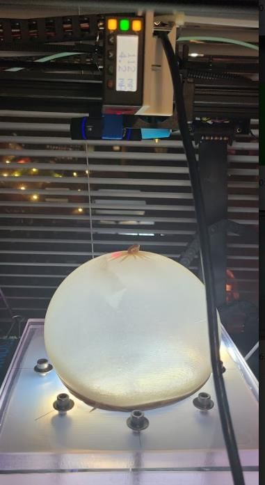
System Design Specification
2.2 Assumptions and Dependencies
The proposed method is intended for large scale additive manufacturing capable of printing
structures out of a slurry-mix such as concrete, but in a lunar surface environment. It is also
assumed that these lunar habitats will use an inflatable bladder that act as a form and support for
the extruded medium to adhere to, similar the methods utilized by NASA’s attempt to create an
lunar greenhouse (Hublitz, Henninger, Drake, & Eckart, 2004).
It is also assumed that supplies and equipment have already been transported from Earth and
prepared for construction. This assumes that a structure has already been designed, an inflatable
support structure has been inflated and a machine capable of extruding a medium, such as
Martian regolith over the inflatable is functional. The intention of the sensor feedback loop is to
merely complement the existing machinery so that the manufacturing process can account for
influences inherit from terrain topology or partial inflation of an inflatable bladder.
2.3 Constraints
As space travel has yet to become economical, localized terrestrial testing of the sensor
packages will be conducted. It will be assumed that environmental influence of remote planets
will need to be considered but the same variables are present on Earth such as temperature and
atmospheric pressure. Likewise, the size and type of machine needed for such endeavor is not
within economical budget during a proof-of-concept prototype, instead an ‘off the shelf’ CNC
machine will be utilized but learned processes will still be translatable.
2.3.1 CNC Machine
As previously mentioned, the scaled down approach will utilize a Tronxy CoreXY X5SA
‘3D Printer’, but slightly modified to be able to support the introduced feedback sensor package.
This machine is limited to three axis movements which can constrain necessary movements,
where as a machine with additional axis may have a larger range of motion.
2.3.2 Inflation
To simplify the prototyping, a small dome made of a silicone elastomer was created. This
dome will emulate a similar air bladder that may be used for larger habitats. This dome is
constrained to a single dome, free of complex curves, enabling easier manufacturability and
inflation.
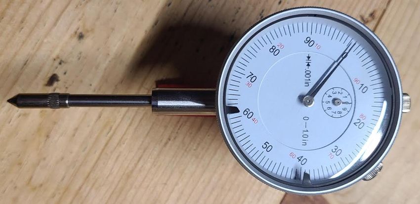
2.4.3 Extruder
A final constraint is that there is no extrusion system within the prototype setup. To
simplify the experiment, the decision to omit an extrusion system and an extruder material as
these introduce system performance and material properties outside the scope of the study.
Instead of an extruder, a dial indicator will be utilized (Figure 2). While there is no extruder
attached, the dial indicator still acts as a tool as there is a tip similar to an extruder nozzle. An
advantage of a dial indicator is that it can be cross validates the distance computed by the
introduce feedback loop.
7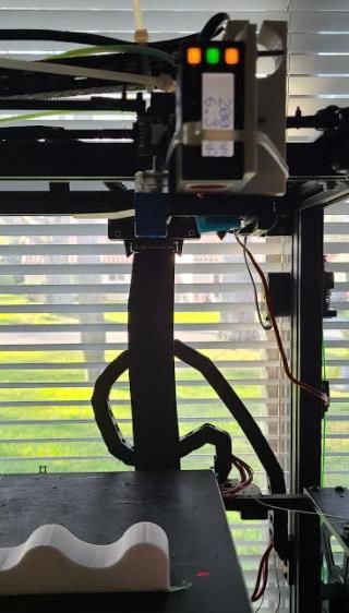
System Design Specification

                            Figure 2 Dial Indicator Used for Distance Displacement

    3 System Architecture
     Utilizing the proposed laser sensor feedback package, which consists of a laser gauge, a
precise machine manipulation over airbladders can be realized. Continuously sampling the where
the extrusion tooltip (dial indicator) is in reference to the toolpath and inflated bladder, dynamic
height adjustments can be made. This correction is done by modifying the extrusion pre-
programmed toolpath which is which is fed line by line to the manufacturing machinery by
correcting the Z heigh before execution.

     This proposed package acts as an in-between, from the tool pathing source file and the
machine. The machines position is checked and measured against actual position and desired
position. If the coordinates are correct, the software executes the original movement command. If
the distance is incorrect, modifications are conducted, and the modified coordinates are sent to
the machine. The entire process is done inline, in a live manufacturing environment with little to
no difference in manufacturing time compared to a non-introduced feedback loop file.

3.1 Hardware Architecture
      There are 4 major physical components required for introduced feedback loop, which
include a CNC Machine, a laser gauge, an Analog to Digital Converter (ADC), and a software
Host Controller. A brief description of each utilized component is given, and its role its role in
the process.

3.1.1 CNC Machine
         The CNC machine used during the evaluation is a commercial off the shelf Tronxy
CoreXY X5SA 3D printer, which has its own onboard CNC controller that is responsible for
interpreting GCODE commands into motor movements. These motor movements drive multiple
axis drives such as X, Y and Z axis motion. In the proposed test environment, the CNC machine
accepts GCODE(toolpathing file) commands from a host controller as well as reporting its
position back to the host controller. This CNC machine has also been equipped with an off the
shelf laser gauge and dial indicator as it’s tooling to manipulate. A diagram representing the
controller’s operation is show in Figure 3.

                                                      8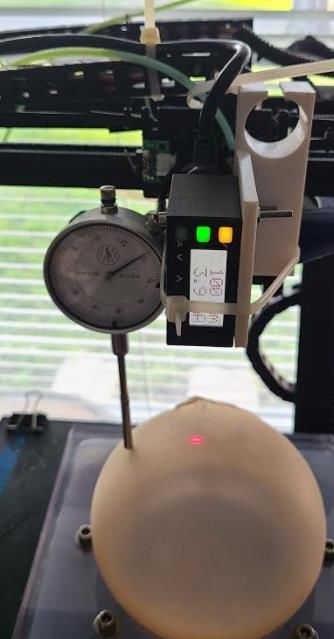
System Design Specification

                            Figure 3 CNC Controller Internal Logics and Controls

3.1.2 Laser Gauge
       Utilizing a Banner L-Gage 250 Laser probe, a precise distance measurement can be
achieved by a non-contact method between an object surface and laser probe. These distance
values are mapped to an analog current value. These ampere values range between 2mA and
40mA which are interpreted by a secondary device called a Analog to Digital Converter (ADC),
such as the Automation Direct P100AM.

3.1.3 ADC
        The Automation Direct P100AM is a microcontroller with an P1-ADL08 expansion
board allowing the system to interpret analog values, such as those sent by the laser gauge and
convert the values to a digital signal. The P100am also maps the analog values to a distance
value, in a string format, allowing values to be sent over a serial connection (USB), allowing to
be interpreted on devices like the ‘Host Controller’.

3.1.4 Host Controller
         A ‘Host Controller’ is responsible for accepting laser gauge distance values, referencing
a line of GCODE containing cartesian coordinates (Figure 4), as well as interpreting where the
CNC is currently located in 3D space. The host controller probes values from all the sources,
either over serial communication or a file(s) locally stored through computation will determine
what offset a Z value needs to be augmented. These correct line of GCODE is then sent to the
CNC machine for execution. A flowchart depicting information flow is represented in Figure 5.

                                                     9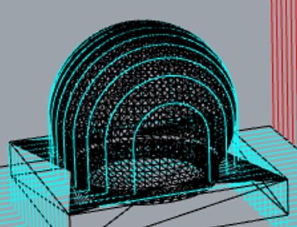
System Design Specification

                                Figure 4 Example of Coordinate Commands

                               Figure 5 Operations Flow Between Subsystems

        Utilizing the Tronxy CoreXY X5SA 3D printer, slight modifications were conducted
such as removing the stock extruder hardware and creating a mount to support a laser gauge and
dial indicator. A decision to use a dial indicator instead of an extruder nozzle was the added
benefit of having a visual distance feedback inherit with a dial indicator. Identical practice of
tooltip height adjustment would apply to such extruder nozzle that may be used for a lunar
extruder habitat.

                                                   10
System Design Specification
In Figure 6, a visual representation of the laser and dial indicator is shown. It should be
noted that the laser optical eye and tooltip have a displacement value that must be accounted for
when doing a height comparison. There is also a secondary offset in the lateral in the X-direction
that must also be accounted for, Figure 7 & 8 give a representation of such displacements. Each
of these offsets are defined and accounted for within the host controller software. In this
experiment, there is only a single laser forward of the dial indicator which caused a limitation to
only a forward movement height comparison. Highlighted within the design limitations, a
secondary aft mounted laser would allow bidirectional z-height comparison.
Figure 6 CNC Machine Equipped with Dial Indicator and Laser Gauge
Figure 78 CNC Laser Displacement Figure 7 CNC Laser Displace Infographic
11System Design Specification
3.2 Software Architecture
Within the system, there is only three pieces of software running, the factory controller
software, the P100AM Automation Direct Analog to Digital controller and the custom-made host
controller software. The CNC controller is running an open-source unmodified version of a
‘Marlin 2.0.7.2’ 3D printing operating system, capable of handling the functions needed to
control and receive GCODE from an external source (MarlinFW, 2021).
Both the P100AM and host controller have custom software written for the proposed
application. The P100AM software is simplistic as it merely interprets a 0-20mA analog input at
10-bit resolution, which in turn converts the analog value to a digital value and sent across a
serial communication to the host controller (Figure 10).
Figure 9 Automation Direct Laser Subsystem
The of the two custom made software applications, the host controller is the most
complex. The host controller communicates with two secondary devices over a serial connection
with a baud rate of 115200, which allowing for a high throughput of data (Dawood & Dawoud,
2020). The host controller is responsible for delegating commands to the CNC machine based
once data has been collected, such as present machine position and laser distance values. The
host controller is the bridge between all systems and responsible for completing the closed loop
position system. The host controllers responsibility is not to send a command to the CNC
machine until the CNC present position is obtained, the laser gauge distance is received, and any
computation corrections have been conducted, only then will the host controller send the a
command to the CNC controller. A simplified process is shown in Figure 10, whereas a more
thorough and logic breakdown is outline in the future software section.
12System Design Specification
Figure 10 Dynamic Software Adjustment Flowchart
3.3 System-to-System Interfaces
As there are three core systems that interface, the CNC machine, Analog to Digital
Converter and the Host Controller, a flowchart representing how each system interacts and
shares information is provided in Figure 11. The flowchart also illustrates the interchange of
corrected coordinate commands, but a more detailed approach is defined in the ‘Software
Design’ future section.
13System Design Specification
Figure 11 System of System Data Flow
4 Mechanical Design
While the final goal is to have a remote manufacturing system on a lunar planet, a more
simplistic localized approach shall be trialed first. To minimalize complexities, a cartesian style
machine equipped with a dial indicator was chosen to minimalize troubleshooting and
maintenance/development of supporting systems, such as an extruder and pump. The Tronxy
CoreXY 5SA was chosen for its cost effectiveness and turn-key solution to begin physical
trialing, however due to its cartesian gantry system and limited number of axis, the system
cannot reach certain volumetric areas such as undercuts (Figure 13). A future advancement
would be to utilize an industrial robotic arm such as ABB or KUKA, as these systems can have 9
Degrees of Freedom (DOF) allowing a tool head to be manipulated (Figure 12) into areas unable
to be reached by a cartesian system (Lai, Villacis Chavez, & Ding, 2018).
14System Design Specification
Figure 12 9-DOF Kuka KR-240-R3100 Ultra K, by Reddot, 2020, from https://www.red-dot.org/project/kuka-kr-quantec-210-
r2700-45875
Figure 13 Low-Resolution Toolpath Simulation emulating undercuts
As the primary objective of this prototype is to validate the ability to maintain a surface
offset, only the bladder surface facing outward from build surface will be evaluated. Even though
the logic and controls are configured to work within an XYZ cartesian system them same method
cand be adapted to work in more complex environment such as that of an industrial arm.
Likewise, even though the extrusion process will not be evaluated, the ability to keep a dial
indicators tip at a defined distance will translate directly to the ability to manipulate an extruder
nozzle.
Like the proposed methods in “NASA Centennial Challenge: 3D-Printed Habitat”, using
airbladders as a support structure for lunar regolith (Prater, Kim, Roman, Mueller, 2018) seemed
ideal as they can store in a small footprint when not inflated, making them easy to handle and
transport in vehicle such as a rocket payload section (Mahoney, 2015). A scaled down silicone
airbladder has been created with a membrane thickness of 12.7mm and an arc radius of 2.75”
15System Design Specification
when inflated with 10 psi. It is important that the intended bladder surface be non-reflective nor
translucent so that the laser gauge can properly gauge the surface without any distortions, where
translucently is a factor, a material can be added to mitigate such issues . An exact reflective
threshold of lux and reflectiveness is defined within the Section 4.3 in the ‘Specifications
Document’. In Figure 14, a rendering of the cartesian style CNC machine is shown conjunction
with a dial indicator, laser gauge, and a mock inflatable bladder (green). In the following
section, a more detailed description of each mechanical piece will be outlined.
Figure 14 CNC Gantry with Mock Inflated Balloon
4.1 CNC
This prototype utilized a TronXY X5SA ‘3D Printer” due to its affordability, ability to
read generic CNC .GCODE files and its large building volume. As this machine is utilized for all
motion control, much of the prototype’s limitations are driven by the capabilities of this machine.
Respective limitations have been defined by the manufacture (TronXY) and adopted within the
‘Design Limitations’ document within this prototype.
4.2 Laser
The Banner L-Gage LE250 laser gauge with a 4-20mA output was utilized as the distance
gauging device due to its accuracy and LCD screen readout (Figure 15). While Banner makes an
identical model with a digital output instead of an analog output, the decision to utilize an analog
approach was to mitigate and electronic noise influence which may distort the accuracy
16System Design Specification
(Precision Digital, 2017). Like the CNC machine, may limitations and constraints with this off
the shelf sensor, likewise its respective limitations were adopted and accounted for during testing
and reflected in the ‘Design Limitations’ document.
Figure 15 Banner L-Gage LE-250 3D Rendering
4.3 Balloon
A fundamental element proposed for additive manufacturing habitats is an inflatable
membrane which an extruded substrate can attach and form over (Litkenhous, 2019). This
membrane has the potential to remain inflated as a protective atmospheric shell or has the
possibility to be deflated and reinflated at a secondary location (Finckenor, 2018) While the scale
of these bladders are outside the operating envelope (Claim: SP#1) of the CNC machine, a
smaller custom silicone bladder was made. A mold was created and injected with Silbion 4410
two-part silicone which resulted in a silicone bladder. The bladder can safely withstand 10 psi
and inflate to a spherical dome shape. Figure 16 pictures a testing jig that compresses the air
bladder and while leaving a circular void helping control the inflation process. Utilizing this jig
will assist in the physical testing and validation of the project.
Figure 16 Custom Airbladder Dome (Deflated)
17System Design Specification
4.4 Stocking Cover
A limitation of the Banner LE-250 is the inability to accurately gauge a translucent
surface (Claim: SP#12), during the testing phase, it was discovered that the silicone becomes too
translucent resulting in false data. To mitigate this inherit characteristic, a thin textile such as a
stocking was donned over the inflated geometry (Figure 17) which reinstated the ability for the
laser gauge to record accurately.
Figure 17 Inflated Bladder with Stocking
4.5 Dial Indicator
As the intended application of the proposed dynamic adjustment would be used in a
extrusion process or 3D printing, a means of validating that the CNC machine can dynamically
adjust needs to be validated. To simplify the equipment setup, a decision to omit any extrusion
components and to utilize a dial indicator instead was made. It is assumed that the dial indicator
tip acts in parallel of that of an extrusion nozzle. A secondary benefit of utilizing a dial indicator
is its ability to visually represent any displacement along the Z axis which cross validated the
Banner LE-250 laser gauge. It is assumed that the dial indicator should not measure a value
outside the defined tolerance (Claim: SP#26) as the software adjust the machine so that dial
indicator is always at a user defined offset from the surface.
18System Design Specification
5 Electronic Hardware Design
In the adaptive feedback loop, there is a subassembly reasonable for probing a laser
gauge for depth values. This subsystem consists of a microcontroller and an expansion board
capable of interpreting analog signals from the laser gauge into a digital serial connection that is
later interpreted by the host controller. The sub assembly consists entirely of off the shelf
components with a plug and play interface, which are manufactured and sold by Automation
Direct.
In Figure 18, the subassembly is illustrated with respective each sub-component. The sub
assembly consists of a power supply (P1-01AC), a microcontroller (P1AM-100) and an
expansion boards capable of reading 4-20mA sensors such as the P1-04ADL-2. While the
P1AM-GPIO expansion board is pictured, it has not been utilized within the subassembly but
may be utilized for future use such as interfacing with secondary hardware.
Figure 18 Automation Direct Laser Subassembly, by Automation Direct,2020e, retrieved from
https://ftp.automationdirect.com/support/drawings/arduino.zip
5.1 P1-01AC PSU
The P1-01-AC PSU is a power transformer that provides electrical power to its connected
devices within the sub-assembly. The power supply accepts 120-240VAC power and converts it
into 24VDC, providing 0.67 amps, which is sufficient to power all the devices within the laser
subassembly (Automation Direct, 2020c).
5.2 P1AM-100
The P1AM-100 is the main logic controller that is responsible for delegating tasks, such
driving subsequent assembly devices to capture analog data or toggle digital devices. The main
responsibility in this configuration is to poll the expansion device (P1-04ADL2) for analog date
19System Design Specification
sent by the laser gauge. This data is converted to a digital signal and relayed to the main host
controller so it can be used to augment the toolhead position.
The P1AM-100 also consists of an ATMEGA chipset, which is commonly utilized in
microcontrollers, more specifically Arduino platforms (Automation Direct, 2020b). This allows
the ability to run the widely adopted programming language C/C++ on this microcontroller
enabling ease of use and interoperability with other devices (Automation Direct, 2020d)
5.3 P1-04ADL-2
The expansion board (P1-04ADL-2) utilized within the prototype has the capability to
read up to four devices simultaneously which allows the opportunity to gauge other sources to
potential close loop other metrics. In Figure 19, a wiring diagram is given denoting electrical
feeds, sensor connections and communication outputs.
Figure 19 Wiring Diagram of Laser Gauge and LE-250
P1-04ADL-2, enabling the device to read common industrial standard 0-20mA sensors at
a 10bit resolution (Automation Direct, 2020b) and converting them into a digital signal. This
digital signal is then parsed and converted to a digital distance value.
5.4 Banner L-Gage LE-250
While the Banner L-Gage LE-250 laser gauge has been outlined within Section 3.1.2, the
laser has basic functions that have been configured for this trial. Within the settings of the laser
gauge, the ‘measuring speed’ (Figure 20) was set to ‘slow’, which allows for the best accuracy
needed for the experiment, yet a high enough refresh rate to supplement the dynamic adjustment.
20System Design Specification
Figure 20 L-Gage Banner Speed Settings, by Banner Engineering Corp., 2020b, retrieved from
https://info.bannerengineering.com/cs/groups/public/documents/literature/175094.pdf
The items identified within 5.1-5.4 make up the entire electronic hardware package used
during the prototyping phase. In figure 19, a schematic view of the entire package was provided,
and in Figure 21 a physical representation of the wiring is shown.
Figure 21 Automation Direct Laser Subassembly Electrically Wired.
6 Software Design
To perform such dynamic controls, a marriage of multiple pieces of software are utilized.
This blend of software consists of both off-the-shelf software as well as custom made control
applications. The proceeding section will provide an overview of each software and their needed
inputs and outputs utilized during the prototyping phase. In figure 22, a high-level view of
software communication is shown.
21System Design Specification
Figure 22 High Level Software to Software Flow
6.1 Prepared Toolpath
Identified in Requirement SP#39, a prepared toolpath, commonly known as a .GCODE
must be generated first. These toolpath generation must be of the intended shape which the
coordinate system must have define incremental X and Y movements no greater that the laser to
tool tip displacement (Claim: SP#38) nor a resolution greater than 0.1mm (Claim: SP#8). The
prepared toolpath must also have a defined delay (Claim: SP#10) between each coordinate
execution so that These constraints ensure the any toolpath movements can be dynamically
adjusted for during the execution of the toolpath. In Figure 23, a small sample of .GCODE is
shown. This sample demonstrates acceptable .GCODE in which the X coordinates are indexed
at 1.00mm and a 10ms pause between the execution of the next movement command. This
snippet of code is taken from validation test #1, in which the machine traverses in a right to left
motion, a visual representation of the entire toolpath is seen in Figure 24.
22System Design Specification
Figure 23 Cartesian Coordinate System with Introduced Pauses
Figure 24 Simulated Toolpath In X+ Direction
23System Design Specification
6.2 Host Controller
The Host Controller application (Figure 25) has been developed “in-house” and the
pinnacle function of the dynamic adjustment. The host controller is responsible for probing both
the CNC machine and the laser controller for values and augmenting a user define .GCODE file
to ensure the tool tip remains at an intended offset from the inflated surface. In section 6.2.1 and
6.2.2 defined inputs and outputs are described.
Figure 25 GUI Of Host Controller Software
6.2.1 Input
Within the host controllers’ responsibilities is to gather data from secondary devices such
as the laser controller, it also considers user defined variables like sensor offsets and intended
surface displacement.
6.2.2 GCODE
Defined in requirements document claim SP#8, a prepared tool path is required in which
the host controller can evaluate and modify if changes are necessary. These toolpaths are user
generated and inputted a .GCODE file.
6.2.3 Laser Gauge Controller
An output from the laser gauge controller is a measure distance from the from the laser
optics to the measured surface (Claim: SP#12) in a digital format sent over serial USB (Claim:
SP#17).
6.2.4 CNC Machine
Inherit with the control software installed on the TronXY CNC machine, after every
command executed the CNC controlled echo’s its command confirming that the machine has
executed the command and ready for the next (Claim: SP#29). This status echo is an output of
the CNC machine and a needed input for the host controller, this echo contains the machines
position coordinate data (Claim: SP#30) which is used during in the manipulation.
24System Design Specification
6.2.5 Laser Vertical Offset from Tool Tip
A user defined variable is a physical distance displacement from the laser optic and the
tooltip in relation to the Z axis (Claim: SP#23). This value will change based on physical
machine set up.
6.2.6 Laser Lateral Offset
A user defined variable is a physical distance displacement from the laser optic and the
tooltip in relation to the X axis (Claim: SP#23). This value will change based on physical
machine set up.
6.2.7 Laser Vertical Offset from Tool Tip
A user defined variable is a physical distance displacement from the tool tip and the
measured surface in relation to the Z axis (Claim: SP#23). This value will change based on end
user’s intent
6.2.8 Operations
To validate a correct z-height, three components are necessary, which include Z-
coordinate generated by the CAM software, a measured displacement and the fixed delta
between the laser gauge and the extruding nozzle tip (Claim: SP#22).
A known displacement between the laser gauge optics and extruder nozzle is defined,
(Section 6.2.1.4) which is subsequently subtracted from the laser gauge reading 6.2.1.2, resulting
in the distance between the surface and extruder nozzle (Section 6.2.2). Thus, measured height
reading is then compared to the CAM file where a Z-coordinate was generated based on a true-
static design. Due to outside influences, this surface may be position greater or less than the
current nozzle position but can still be adjusted for Claim #:####
Comparing the augmented laser height against a CAM generated height, a delta can be
generated. This delta is applied to the base CAM file by the System Controller where the heigh is
augmented and send to the CNC machine.
6.2.9 Output GCODE
After the collected data and post processing has been completed, the host controller
performs dynamic computation to adjust so that the tooltip maintains a fixed distance from a
surface defined in 6.2.1.6 and satisfies Claim: SP#22. The output is a modified .GCODE which
is sent over serial USB (Claim: SP#25) so that the CNC machine can execute the augment
command.
6.2.10 Controller Augmentation
The laser controller consists of an Arduino based microcontroller (P1AM-Automation
Direct) with an analog expansion board (ADL-02), which is capable of reading current values
between 4-20mA output devices, such as a laser gauge (Banner LE-250). Using the
microcontroller, the collected sensor values were converted from 13-bit counts to a voltage
reading. These readings were then mapped based on laser documentation and known distances,
25System Design Specification
as output is linear with measured distance, a slope formula was derived. The resulting distance
value is then sent over a serial communication line to the host computer. These values are then
parsed by the host controller (Claim: SP#27) for future operations.
6.2.11 Input
The sole input of the laser microcontroller (P1AM-100) is the analog value outputted by
the Banner LE-250 laser gauge. This output from the laser gauge may vary between 4-20mA
depending on the distance measured.
6.2.12 Output
The sole output of the laser microcontroller is a digital distance value (Claim:SP#16),
which is converted to a digital signal and sent to the host controller via serial USB (Claim:
SP#27). To convert the received analog inputs to the correct digital output, the following code
was created and uploaded to the P1AM-100. The code was also cross validated to measure
accurately against known distances between the lasers operational range define in Validation
Test #1. It should be noted that the code is design for a 13-bit resolution module, however
Automation Direct makes other modules with a higher resolution if needed (Automation Direct,
2020b). In Figure 26, a snippet of code running on the P1AM-100, which is responsible for
analog data conversions to a physical distance, then broadcasting the values to a serial output.
Figure 26 Example of Digital Laser Code Conversion
7 Verification and Validation Test Plan
The proposed sensor assisted manufacturing process will be verified and validated through
functional testing and prototyping. Through the iterative prototyping and design process, six
steps commonly used in software development were used:
1. The identification of functions that the software is expected to perform
2. The creation of input data based on the function's specifications
3. The determination of output based on the function's specifications
4. The execution of the test case
5. The comparison of actual and expected outputs
6. To check whether the application works as per the customer need (Coles, 2016).
To ensure the feedback sensor package is being designed correctly for an additive
manufacturing consumer such as a space agency, a verification and validation plan have been
26System Design Specification
implemented. Utilizing a verification and validation plan will allow the system to be fully
defined identifying if the sensor package works functionally as well as fully capturing the end-
users needs. All identified tasks discovered within the functional testing steps, including the
verification and validation metrics were tracked within a traceability matrix (Appendix II)
allowing for an iterative development and testing criteria needed to ensure all requirements have
been satisfied.
7.1 Verification Plan
As the intention of the depth sensing laser gauge is to complement existing manufacturing
equipment, quantitative data can be collected from physical testing that can be used to assist the
verification process. This physical testing allows for an iterative design approach where the next
phase of development cannot proceed until the first step has been verified. As an example, the
ability to maintain a prescribed distance from a surface must begin verifying a CNC machine can
be manipulated the ability as well to verify dimensional accuracy. A series of tests were
conducted, and the related data can be found within Appendix 1.
7.2 Validation Plan
Utilized the six-step approach, steps 1, 2 and 3 will address the end user needs by defining
function, inputs and needs. Each element will be assigned a task number and assigned any
dependencies. Utilizing a traceability matrix, this method ensures all requirements and functions
are outlined to help clarify the intended functions and limitations.
To validate such claims and dependencies, a series of physical testing procedures will be
are performed to ensure they can satisfy any functional claims and meet and satisfy and
dependency claims made within the traceability matrix found in Appendix 2
7.3 Traceability Matrix
A Traceability Matrix will be utilized for addressing all critical constraints and requirements for
the proposed system. While not all claims were denoted in the proceeding sections, the claims
were written to assist in selecting components not used within this test. This is evident in the first
series of claims regarding the CNC machine needs, using an off the shelf machine such as the
TronXY 3D printer, these dependencies were inherited with the machine.
The matrix highlights system claims, roles, description, validation test and completion status.
Utilizing such matrix allows for an organized quick reference and accountability within the
system design. An example matrix line has been provided below.
Claim # Criteria Name Role Description Validation Test# Status
SP:#
8 External Dissemination Opportunities
The application of this laser feedback loop may find applications outside of inflatable
airbladder manufacturing. The application developed herein will also be submit to the 2021
27System Design Specification
American Society of Mechanical Engineers (ASME) International Manufacturing Science and
Engineering Conference. The conference is being offered in a virtual environment on June 21-
25th and intended to showcase innovative manufacturing processes. The prototype study
developed for this master’s program will be submitted to the conference’s call for papers
regarding ‘Smart Additive Manufacturing (American Society of Mechanical Engineers, 2020).
This study will complement the conference well as the process incorporates sensor feedback
and intelligent manufacturing processes, which is the keynote topic of the conference.
28System Design Specification
9 References
American Society of Mechanical Engineers. (2020). The Manufacturing Engineering Division
(MED) of ASME sponsors the Manufacturing Science and Engineering Conference
(MSEC) every June. Retrieved from https://msec.secure-platform.com/a/
Automation Direct. (2021). Productivity1000 controller Analog I/O Modules. Retrieved from
https://www.automationdirect.com/adc/shopping/catalog/programmable_controllers/produ
ctivity_series_controllers/productivity1000_(stackable_micro_plc)/analog_i-z-o
Automation Direct. (2020a). P1AM-100. Retrieved from
https://www.automationdirect.com/adc/shopping/catalog/programmable_controllers/open_
source_controllers_(arduino-compatible)/productivityopen_(arduino-
compatible)/controllers_-a-_shields/p1am-100
Automation Direct. (2020b). P1-04adl-2. Retrieved from
https://www.automationdirect.com/adc/shopping/catalog/programmable_controllers/produ
ctivity_series_controllers/productivity1000_(stackable_micro_plc)/analog_i-z-o/p1-04adl-
2
Automation Direct. (2020c). P1-01AC Power Supply. Retrieved from
https://cdn.automationdirect.com/static/specs/P1-01AC.pdf
Automation Direct. (2020d). P1AM-100 Arduino Compatible CPU. Retrieved from
https://cdn.automationdirect.com/static/specs/p1amspecs.pdf
Automation Direct. (2020e). P1AM-100 Schematic Drawings [Digital image]. Retrieved from
https://ftp.automationdirect.com/support/drawings/arduino.zip
Banner. (2015). L-GAGE® LE250/550 Analog-Discrete Laser Sensors. Retrieved from
https://info.bannerengineering.com/cs/groups/public/documents/literature/175093.pdf
Banner Engineering Corp. (2018a). Figure [3D Schematic of Banner LE-250]. Retrieved from
https://info.bannerengineering.com/cs/groups/public/documents/literature/175094.pdf
Banner Engineering Corp. (2018b). LE-250 User Defined User Settings [Digital image].
Retrieved from
https://info.bannerengineering.com/cs/groups/public/documents/literature/175094.pdf018
Cesaretti, G., Dini, E., De Kestelier, X., Colla, V., & Pambaguian, L. (2014). Building
components for an outpost on the lunar soil by means of a novel 3D printing technology.
Acta Astronautica, 93, 430-450. doi:10.1016/j.actaastro.2013.07.034
Chandra, A., Thangavelautham, J., & Babuscia, A. (2018). Modular inflatable space structures.
2018 IEEE Aerospace Conference. doi:10.1109/aero.2018.8396754
29System Design Specification
Coles, R. (2016). Standard Operating Procedure Software Quality Assurance Testing. Retrieved
from http://robingcoles.com/PDFs/SOP-Sample_Software_QA_Testing.pdf
Hedmond, S. (2017). Inflatable Binishell [Digital image]. Retrieved from
https://www.constructionjunkie.com/blog/tag/benefits+of+binishells
Finckenor, M. M. (2018) Space environmental effects on additively manufactured materials. NASA
Technical Report NASA/TP-2018-
220123. https://ntrs.nasa.gov/archive/nasa/casi.ntrs.nasa.gov/20180006417.pdf
Dawood, R., & Dawoud, P. (2020). Serial communication protocols and standards : RS232/485,
UART/USART, SPI, USB, Insteon, wi-fi and WiMAX (pp. 13-14) . River Publishers.
Hublitz, I., Henninger, D., Drake, B., & Eckart, P. (2004). Engineering concepts for Inflatable
Mars SURFACE GREENHOUSES. Advances in Space Research, 34(7), 1546-1551.
doi:10.1016/j.asr.2004.06.002
Kading, B., & Straub, J. (2015). Utilizing in-situ resources and 3D printing structures for a
manned Mars mission. Acta Astronautica, 107, 317-326.
doi:10.1016/j.actaastro.2014.11.036
Koslow, T. (2020, January 8). Tronxy X5SA pro: Review the specs. Retrieved from
https://all3dp.com/1/tronxy-x5sa-pro-review-3d-printer-specs/
Lai, C. Y., Villacis Chavez, D. E., & Ding, S. (2018). Transformable parallel-serial manipulator
for ROBOTIC MACHINING. The International Journal of Advanced Manufacturing
Technology, 97(5-8), 2987-2996. doi:10.1007/s00170-018-2170-z
Litkenhous, S. (2019). Surface Construction. Retrieved from
https://www.nasa.gov/oem/surfaceconstruction
Mahoney, E. (2015, June 30). Bigelow expandable activity module. Retrieved from
https://www.nasa.gov/content/bigelow-expandable-activity-module
MarlinFW. (2021, February 03). Marlin Gcode. Retrieved from https://marlinfw.org/meta/gcode/
Prater, T., Kim, T., Roman, M. C., and Mueller, R. P. (2018) NASA’s Centennial Challenge for 3D
Printed Habitat: Phase II Outcomes and Phase III Competition Overview. In 2018 AIAA
SPACE and Astronautics Forum and Exposition (p 5405). Presentation can be found
here: https://ntrs.nasa.gov/archive/nasa/casi.ntrs.nasa.gov/20170009010.pdf
Precision Digital. (2017). Back to basics: The fundamentals of 4-20 ma current loops. Retrieved
from https://www.predig.com/indicatorpage/back-basics-fundamentals-4-20-ma-current-
loops
Productivity Open. (n.d.). P1AM-100 Arduino Compatible CPU. Retrieved from
https://cdn.automationdirect.com/static/specs/p1amspecs.pdf
30System Design Specification
Reddot. (2020). KUKA KR Quantec 210 R2700 [Digital image]. Retrieved from
https://www.red-dot.org/project/kuka-kr-quantec-210-r2700-45875
31System Design Specification
10 Appendix 1
A series of tests have been conducted throughout the prototyping phase of the distance
feedback loop in efforts to validate various functions and to drive refinements where needed.
These tests range in methods but test various core functions such as accuracy, repeatability, and
functionality. The following sections will outline the various tests and their intended scope and
outcome that stratifies functional claims or needs.
10.1 Validation Test #1
Table 2: Laser Distance Formula Creation/Accuracy
Goal: Create Formula to Convert mA into Distance
Description: The Banner LE-250 laser gauge by default outputs an analog value when
measuring distance within it’s gauging range. A method to convert such values to a distance
(mm) was needed. Utilizing the P1AM-100, a software solution was created to convert
received values to a distance value.
Method: Deriving a basic program provided by Automation Direct, the P1AM was
programmed to read the analog values from the LE-250 laser gauge. The values now had to be
mapped to a distance value. The laser was displacement a known from an object and the
analog values was recorded. The process was repeated numerous times against a series of
known distances. As the analog values are linear with distance, a mathematical formula was
able to be programmed that converts the received analog values to a distance value.
The tests were repeated with known distance, but instead of reading analog values, the output
was displayed as a distance value. It should also be noted that the LE-250 module has a visual
feedback on the device itself that displays the distance, but this value is not transmitted to
secondary devices.
32You can also read