And Real Space Applications - System Hardening against Upsets CNES
←
→
Page content transcription
If your browser does not render page correctly, please read the page content below
Toulouse – IRIT-ENSEEIHT
                                                      December 13, 2013

System Hardening against Upsets
  and Real Space Applications

                Michel PIGNOL
                        CNES
                           DCT/TV/IN
                    18 avenue Edouard Belin
                31401 Toulouse Cedex 9 - FRANCE

      michel.pignol@cnes.fr         http://www.cnes.fr
Motivation
Rationale for fault-tolerant architectures in the space domain
■ Up to now, space computers are mainly developed with rad-hard ICs
■ Mainly for performance reasons (not for cost reasons), commercial electronic
integrated components (COTS ICs) will probably be more and more used
! For microprocessors (µP), the performance gap is around 50 (average value)
• LEON2 = 100 MIPS peak PowerPC7448 = 5100 MIPS peak
! This gap is growing
• PowerPC is superscalar, not LEON2
■ Due to the SEE sensitivity of COTS, they must be protected by fault-tolerant
mechanisms or architectures
■ SEE protections = high cost / planning overheads
=> it is important to assess carefully the safety/availability requirements
of the project to select the optimal fault-tolerant solution
! Such solutions could range from very simple mechanisms having limited error
detection/recovery capabilities to complete protection with FT archi.
2
M. Pignol – System Hardening TORRENTS 2013, Dec. 13 CNES
OUTLINE
1 – INTRODUCTIVE PART
■ Avionics architecture of a satellite
■ SEE – Effects of radiation on digital parts
2 – ARCHITECTURE AND SYSTEM PROTECTIONS
■ 2-A – FDIR overview
■ 2-B – Links
! Avionics buses
! Sensor/actuator links
! High speed serial links
■ 2-C – Memory units
■ 2-D – Processing units
! Time replication
! Structural duplex
! Triplex / Quadruplex
! Micro-synchronized triplex
! Fault-tolerant trade-off with analysis of theoretical case studies
3 – REAL CASE STUDIES
■ ATV, the ESA Automated Transfer Vehicule
■ MYRIADE, the CNES micro-satellite family
■ CALIPSO, a Franco-American mini-satellite
■ REIMEI (INDEX), a Japanese small satellite
4 – CONCLUSION
3
M. Pignol – System Hardening TORRENTS 2013, Dec. 13 CNES
Acronyms CNES Centre National d'Etudes Spatiales, the French Space Agency
ESA European Space Agency
ADC Analog to Digital Converter TC TeleCommand
Acq Acquisition TM TeleMetry
ALU Arithmeric and Logic Unit Tx/Rx Transmitter/Receiver
ATV Automated Transfer Vehicule µP MicroProcesseur
Cmd Command (actuation) µSL Micro-Satellite
Cntl Control VLIW Very Long Instruction Word (superscalar DSP
COTS Commercial Off-The-Shelf having several execution units working in parallel)
CPU Central Processing Unit WD WatchDog
CRC Cyclic Redundancy Check wrt With Regard To
CTXT Context (software variable)
DMT Duplex Multiplexed in Time
DRAM Dynamic RAM
(time replication at task level, CNES architecture)
DSP Digital Signal Processor
DT2 Double Duplex Tolerant to Transient
EDAC Error Detection And Correction
(mini structural duplex at task level, CNES architecture)
FDIR Fault Detection, Isolation and Recovery
N-MR N-Modular Redundancy
FT Faut-Tolerant
DMR Double-MR = Duplex
FTC Fault-Tolerant Computer
TMR Triple-MR = Triplex
GIPS Giga Instructions Per Second
QMR Quad-MR = Quadruplex
IC Integrated Circuit
I/O Input/Output MBU Multiple Bit Upsets
ISS International Space Station SEE Single Event Effect
NG Next Generation SEFI Single Event Functional Interrupt
OBC On-Board Computer SEL Single Event Latch-up
PARAM Parameter (software variable) µSEL Micro latch-up
PF PlatForm (of a satellite) SET Single Event Transient
PL PayLoad (of a satellite) SEU Single Event Upset
R/W Read/Write TID Total Ionizing Dose 4
M. Pignol – System Hardening TORRENTS 2013, Dec. 13 CNES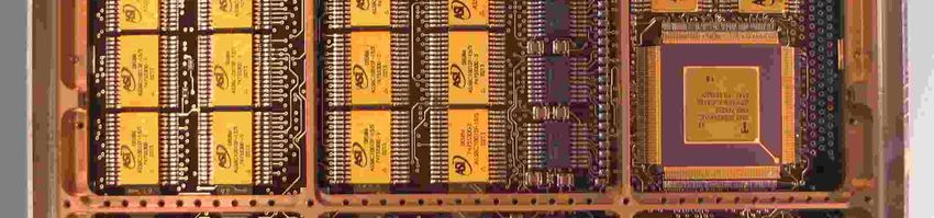
1 – INTRODUCTIVE PART
© CNES / ISRO
MEGHA-TROPIQUES: a
French / Indian mission to
improve our knowledge on
the tropical climate system;
5
M. Pignol – System Hardening TORRENTS 2013, Dec. 13 launched
CNES in 2011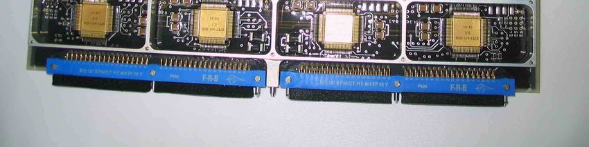
Nb of input/output interfaces
for small/large satellites:
Avionics architecture of a satellite Thermistors acq.: 30 to 200
Analog acq.: 30 to 100
Status acq.: 30 to 60
Heater cde: 10 to 100
Image Bi-level cde: 20 to 50
Sensors/Actuators sensor Low rate serial links: 5 to 15
+ Additional specific I/O i/f for:
Video electr. Unregu- TM/TC
Avionic Pyros, reaction wheels, magneto-
lated links &
(ADC) power reconf.
buses & torquers, gyroscopes, magneto-
PF Mntrg&Cntl other links meters, GPS, thrusters, etc.
Tx/Rx HSSL bus signals
PL Mntrg&Cntl
Nominal computer Avionic bus
Nominal Data
unit
Cross-strapped compression
TM/TC
interconnection HSSL
Nom.
Nom.
Central Processing Nom.
Nom.
Nom.
Nom.
Nom.
Nom.
Red.
Red.
Red.
Red.
Red.
Red.
Red.
Red.
PF Mntrg&Cntl Mass
Tx/Rx
Redundant computer Avionic bus memory
Redundant
TM & TC &
TM Mass
Memory
Converter
TM/TC HSSL
Reconf.
Power
I/O 2
I/O 3
I/O 4
I/O 1
Unit
unit
unit
unit
unit
data Video Tx
High rate
Platform Sensors/Actuators
Payload 1 to 10
Gbit
Internal links and buses
Main sensitive
elements wrt SEE
Video
Usual budgets for small satellites Usual budgets for large satellites
Mntrg&Cntl
data
computers
Redundancy: No redundancy Nominal + Redundant units
Volume = 3,3 litres / 5 boards Volume = 30 litres / 15 boards
Ex. for
Hot
Mass = 3 kg Mass = 19 kg
Warm
Power dissipation = 6 W Power dissipation = 55 W
Cold
6
M. Pignol – System Hardening TORRENTS 2013, Dec. 13 CNES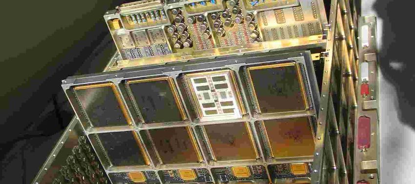
© EADS ASTRIUM
© ESA / CNES
© CNES / D. Ducros
ALPHABUS, a family of
European Telecom satellites
with a common platform
from EADS ASTRIUM and
THALES ALENIA SPACE
Max 8800 kg
Max 18000 W
The 1st launch is
ALPHASAT
in 2013
Launched Launched
in 2002 in 2005 .
3000 kg 6000 kg
2400 W 14000 W
5.7x3.1x3.1 m 7x2.9x2.3 m
2x60 km swath 45 m solar arrays
2.5 m resolution 10 m diam. antenna
INMARSAT 4-F1 for
SPOT 5 for mobiles-to-mobiles
© CNES / P. Le Doare Earth observation telecommunications © EADS ASTRIUM
7
M. Pignol – System Hardening TORRENTS 2013, Dec. 13 CNES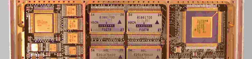
EADS ASTRIUM computers
TM & TC & Reconf. board,
including 3 ASTRIUM ASICs:
- TC processing and reconf.
- TM formatting and routing
- Storage control for reconf.
GSTB-V2 computer (Galileo
System Test Bench; proposal
for Galileo satellites)
© Courtesy of
EADS ASTRIUM
CPU board using Fyber Optic
ASTRIUM Multi-Chip- Gyro Electr.
Module (2003) based Module
on ERC32SC space µP (I/O board)
8
M. Pignol – System Hardening TORRENTS 2013, Dec. 13 CNES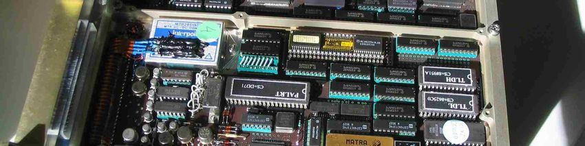
SEE – Effects of radiation on digital parts
SEE : Single Event Effect
■ SEE concerns all effects due to a single particle
! SEE in digital ICs = SEL + µSEL + SEFI + SET + SEU + MBU
■ SEL – Single Event Latch-up
! Local short-circuit
! Detection: loss of functionality or over-consumption / Protection: power-cycling
! It is a good practice to avoid components which are sensitive to SEL
! And if not possible, to limit their usage and to protect them with adequate solutions
■ SEFI – Single Effect Functional Interrupt
! The component is put in a blocking state and a reset is not always capable to bring
it back into an operational state
! Detection: loss of functionality (as for SEL)
! Protection: reset (optional but recommended) and/or power cycling (mandatory)
■ SEU/MBU – Single Event (Multiple Bit) Upset / SET – Single Event Transient
■ Goal of faul-tolerant architecture protections
! Thanks to DSM technos, more and more COTS parts are compliant with TID (Total
Ionizing Dose) and SEL space constraints
! But all digital COTS components are sensitive to transients and upsets
! The presentation targets SEFI / SEU / MBU / SET mitigation, mainly on µP 9
M. Pignol – System Hardening TORRENTS 2013, Dec. 13 CNES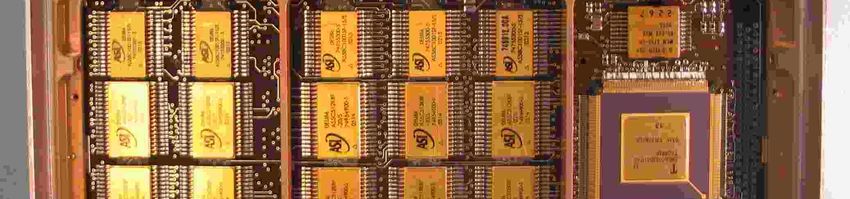
■ An ingenious SEL mitigation example (MYRIADE real case):
+
minimizing the
OFF/ON
number of parts Watchdog Qn .. Vcc
Current
and, nevertheless, CLOCK timer Q1
. ERROR
limitation
R-threshold
implementing both Reset Q0
detection and both
Vcc
mitigation methods
Microprocessor
RefreshWD
■ Whatsoever the 'detection' method is, it is a good practice to have a gradual
'recovery' process based on several levels, for instance:
! First attempt following a detection: a quick 'standard' recovery (i.e. without reset) is
tried (in case of simple effect of an SET/SEU/MBU)
! Second attempt: if the first attempt is not successful, a reset of the computer is done
(in case of more complex effect of an SET/SEU/MBU or in case of SEFI)
! Third attempt: if the computer still does not become operational, then a power supply
cycling is done (in case of SEFI or SEL)
! Such a multi-level recovery process is implemented on CNES MYRIADE
micro-satellite: See Section "3 – Real Case Studies" 10
M. Pignol – System Hardening TORRENTS 2013, Dec. 13 CNESTHALES ALENIA SPACE computers
TM & TC & Reconf. board,
including 2 THALES ASICs:
- TC processing and reconf.
- TM formatting and routing
and including 4 THALES
hybrids for generating
command signals
SMU-V1 computer (Satellite
Management Unit; platform
computer for SpaceBus4000
Telecom family satellites and
Globalstar2 satellite)
© Courtesy of
THALES ALENIA SPACE Satellite
Distribution
and Interface
Unit for
CPU board using Telecom
ATMEL ERC32SC space µP satellites
and COPRES THALES ASIC (I/O board)
11
M. Pignol – System Hardening TORRENTS 2013, Dec. 13 CNES2 – ARCHITECTURE AND SYSTEM PROTECTIONS
© ESA
EUCLID: an ESA mission to
map galaxies, to analyse their
distribution and their apparent
deformation under effect of the
dark matter, for a better
understanding of the dark
matter and its influence on the
origin of the accelerating
expansion of the Universe; 12
launch planned
M. Pignol – SysteminHardening
2020 TORRENTS 2013, Dec. 13 CNES2-A – FDIR overview
13
M. Pignol – System Hardening TORRENTS 2013, Dec. 13 CNESThe FDIR strategy – Fault Detection, Isolation and Recovery
■ Main objective of the FDIR strategy
! To keep the integrity of the satellite (i.e. its operational capability) in presence of
anomalies
• There is not an universal strategy, it is a case-by-case basis definition depending on the
mission and on the considered faulty unit
■ Usual FDIR strategies when an anomaly is detected
" "Satellite survival mode" = minimal mode allowing to keep at an acceptable level the
electric pw, the internal temperature and the TM/TC link with the ground cntrl station
! Earth observation satellites: To pass in the survival mode and to leave to the ground
control station the detection of the source of the anomaly then the selection of the
best recovery strategy
! Telecom satellites: To reconfigure the avionics architecture to try to passivate the
anomaly in order to remain in operational mode as long as possible to comply with
the availability requirements; to limit the survival mode usage to exceptional cases
=> Telecom satellites have an higher autonomy than Earth observation satellites
14
M. Pignol – System Hardening TORRENTS 2013, Dec. 13 CNESThe FDIR strategy (cont.)
■ Recovery action when an anomaly is detected sensors &
! Only few alarms are highly critical and directly start a recovery action actuators
=> examples of such critical alarms => and associated recovery action in case of cold redundancy
- power falling down - switch-off nominal computer and nominal peripheral units
- software watchdog - switch-on redundant computer and a mini. of redund. periph.
- Earth sensor alarm for - then start from scratch and put the spacecraft in "attitude
some missions acquisition & safe hold" mode
! For all the other alarms, the general rule is "to try to confirm the alarm before
starting a recovery action", thanks to the "anomaly filtering process"
■ Some examples of the "anomaly filtering process"
! Time redundancy at the system level
• when a task (thermal control, attitude and orbit control system, etc.) trigger an alarm during a given
iteration, it is checked if the same alarm is still triggered during the next iteration(s) of this task
! Comparison between sensors to confirm an incoherent data
• coupling with dedicated algorithms of linked data issued from gyro sensors and from the star sensor
! Start a BIST (Built-In Self Test) into the intelligent sensor which have issued the
incoherent data 15
M. Pignol – System Hardening TORRENTS 2013, Dec. 13 CNES2-B – Links
16
M. Pignol – System Hardening TORRENTS 2013, Dec. 13 CNES■ Avionics bus: e.g. MIL-STD-1553B data bus
! Detection: Parity bit (or checksum, or CRC)
! Recovery: It is the responsibility of the higher level (e.g. software
application level) to decide the best suited strategy wrt the application
context => a "retry" is usual done (i.e. retransmit the message)
■ For sensors
! Complex sensor: same as for an avionics bus
! Simple sensor: triplication (e.g. all thermistors on CNES SPOT satellite
family), time redundancy
■ For some actuators, protection with the "Arm & Fire" concept
! Such a command requires a first signal (Arm) then a second signal (Fire)
sent by a distinct path, both being ANDed; typically used for pyro elements
■ For HSSL (High Speed Serial Link)
! For image data, retries are not possible (too much data to bufferize)
! Thus, the usual strategy is to select or design HSSL having a very high
BER performance (SEE robustness), and no protection is implemented
17
M. Pignol – System Hardening TORRENTS 2013, Dec. 13 CNES2-C – Memory units
18
M. Pignol – System Hardening TORRENTS 2013, Dec. 13 CNESComparison of the efficiency of several protection codes
Contribution from: A. Peus (CNES - DCT/SB/PS)
Detect 1 error Detect/correct 1 err Detect 2 errors and Detect/correct MBU
correct 1 error
Parity Hamming Extended Hamming Reed-Solomon
Correct 2 symbols
of 4-bits per word
32 1 32 + 25 6 32 + 25 7
or 32 16
Not implemented Critical
tripled
data TMR
Other methods for detection only,
mainly usable for protection
of a block of data: No
8 1 critical
Checksum data
CRC
Signature 32 32 2 x 32
19
M. Pignol – System Hardening TORRENTS 2013, Dec. 13 CNESThe 1st generation
of CNES solid-state
mass memory
Flying on
SPOT 4 satellite and
VEGETATION payload
Sextant Avionique (now
Thales Alenia Space) and
Dassault Electronique
(now Thales Aerospace)
development (1995)
16 DRAM / hybrid
8 hybrids / mem board
18 mem boards / unit
4 Mbits / DRAM
512 Mbits / mem board
9 Gbits / unit
Unit = 37 kg
28 W in hold mode
50 W in R/W mode
20
M. Pignol – System Hardening TORRENTS 2013, Dec. 13 CNES2-D – Processing units / Fault-tolerant architectures
21
M. Pignol – System Hardening TORRENTS 2013, Dec. 13 CNESA general remark
■ Comparators and voters are usually implemented in FPGA / ASIC
either not sensitive to SEE by design (D-FF triplication, etc. => thus
COTS are usable) or implemented in radiation-tolerant technologies
A prototype of a QUADRUPLEX computer
from Matra Marconi Space (now EADS
Astrium France), development for the ex
HERMES European shuttle project (1994)
22
M. Pignol – System Hardening TORRENTS 2013, Dec. 13 CNES2-D – Processing units / Fault-tolerant (FT) architectures
# ■ Time replication
! Time replication at instruction level
– Example of Time-TMR from SPACE MICRO Inc.
! Granularity for CNES FT architectures
! Time replication at task level
– Example of DMT from CNES
■ Structural duplex
– Example of DT2 from CNES
■ TMR-Triplex & QMR-Quadruplex
– Examples issued from the SHUTTLE, GUARDS and ATV
■ Micro-synchronized triplex
– Example of SCS750 from MAXWELL Tech.
■ FT architectures trade-off
■ Other methods and elementary protection mechanisms
23
M. Pignol – System Hardening TORRENTS 2013, Dec. 13 CNESTime replication
■ Principle
! No hardware replication => No extra recurring cost
! The same software is processed N-times successively on the same CPU
! Detection capability: the results of the different replicas are compared
■ Time replication at instruction level
! See the talk "Software hardening" by Politecnico di Torino
24
M. Pignol – System Hardening TORRENTS 2013, Dec. 13 CNES■ Time replication at instruction level: real case example of an industrial
development
TTMR – Time-TMR (Space Micro Inc. – USA)
Piece of Piece of
code Software instructions Computer hardware code
Vote Line Line Line Single
Line Line Line CPU A1-A2-A3 A3 A2 A1 CPU
C1 B1 A1 #1
T=4 T=3 T=2 T=1
Voting
Computer
logic
Line Line Line CPU
Vote Line Line Line hardware
C2 B2 A2 #2
B1-B2-B3 B3 B2 B1
Line Line Line CPU T=8 T=7 T=6 T=5
C3 B3 A3 #3
Vote Line Line Line Software
T=3 T=2 T=1 C1-C2-C3 C3 C2 C1 instructions
T = 12 T = 11 T = 10 T=9
Time-slots Time-slots
TMR architecture Time redundancy architecture
Single
instruction Software instructions VLIW DSP Hardware IC
SEU
Vote Instruct Instruct Instruct ALU
A1-A2-A3 C1 B1 A1 #1 MMU Cache
Clock Cntl
Vote Instruct Instruct Instruct ALU cntl logic
B1-B2-B3 C2 B2 A2 #2
Bus interface …/…
Vote Instruct Instruct Instruct ALU Bus Parallel
cntl I/O
C1-C2-C3 C3 B3 A3 #3
T=4 T=3 T=2 T=1
Clock cycles
© IEEE – Space Micro Inc.
One TTMR possibility… with weakness
(adapted from)
25
M. Pignol – System Hardening TORRENTS 2013, Dec. 13 CNESTTMR – Time-TMR (Space Micro Inc. – USA) (cont.)
Single
Software instructions VLIW DSP Hardware IC Software instructions VLIW DSP
instruction
Not Instr
Vote Instruct Instruct Instruct ALU ALU #1 Repeat 2 instructions
required A1
A1-A2-A3 B3 C2 A1 #1 MMU Cache
99% of Instr 100% of time
ALU #2
time A2
Vote Instruct Instruct Instruct ALU Clock Cntl Comp Compare A1-A2 100%
cntl logic Branch #1
B1-B2-B3 C3 A2 B1 #2 A1-A2 with "free" branch
Bus interface Instr
ALU #3 When NO match,
Vote Instruct Instruct Instruct ALU Bus Parallel A3
cntl I/O Comp complete instr A3
C1-C2-C3 A3 B2 C1 #3 Branch #2
A1-A3 and additional
compare
T=4 T=3 T=2 T=1 T=5 T=4 T=3 T=2 T=1
Clock cycles
TTMR architecture Improved TTMR architecture
…/…
© IEEE – Space Micro Inc.
(adapted from)
26
M. Pignol – System Hardening TORRENTS 2013, Dec. 13 CNESTTMR pros/cons (cont.)
■ Proprietary architecture
! Space Micro Inc. patent
■ Dedicated to VLIW DSP (Very Long Instruction Word - Digital Signal
Processor)
! Given that the ALUs are generally speaking not all fully used, not too
much time is lost due to the time replication
■ The TTMR algorithm is coded into a "post-compiler"
! All the know-how lies in the "post-compiler": instruction replication + vote
insertion + instr.->ALU assignment + instr. reordering to avoid empty slots
! The "post-compiler" must be developed for each targetted DSP
■ The SEFIs are processed by a patented
rad-hard watchdog circuit
27
M. Pignol – System Hardening TORRENTS 2013, Dec. 13 CNES2-D – Processing units / Fault-tolerant (FT) architectures
■ Time replication
! Time replication at instruction level
#
– Example of Time-TMR from SPACE MICRO Inc.
! Granularity for CNES FT architectures
! Time replication at task level
– Example of DMT from CNES
■ Structural duplex
– Example of DT2 from CNES
■ TMR-Triplex & QMR-Quadruplex
– Examples issued from the SHUTTLE, GUARDS and ATV
■ Micro-synchronized triplex
– Example of SCS750 from MAXWELL Tech.
■ FT architectures trade-off
■ Other methods and elementary protection mechanisms
28
M. Pignol – System Hardening TORRENTS 2013, Dec. 13 CNESGranularity for CNES DMT and DT2 fault-tolerant architectures
■ Granularity impact deeply the definition and latency/overhead of FT mechanisms
■ Coarse-grained granularity (macro-granularity) => task operational cycle
! the checking procedure runs at the end of each iteration of each task
! a low number of data to check => minimisation of overheads
! the main fault-containment region
One iteration
of a flight software in a platform computer
of three tasks RTC – Real
Simple example of a static scheduling
Real time Time Cycle
interrupt
Task A
OBT
Task B
AOCS
Macro-
granularity
Task C preemption
Thermal Task C operational cycle only all output data
(but not the huge
number of local data)
Task T must be checked
Background
t
OBT = On-Board Time ; AOCS = Attitude and Orbit Control System
29
M. Pignol – System Hardening TORRENTS 2013, Dec. 13 CNES2-D – Processing units / Fault-tolerant (FT) architectures
■ Time replication
! Time replication at instruction level
– Example of Time-TMR from SPACE MICRO Inc.
! Granularity for CNES FT architectures
# ! Time replication at task level
– Example of DMT from CNES
■ Structural duplex
– Example of DT2 from CNES
■ TMR-Triplex & QMR-Quadruplex
– Examples issued from the SHUTTLE, GUARDS and ATV
■ Micro-synchronized triplex
– Example of SCS750 from MAXWELL Tech.
■ FT architectures trade-off
■ Other methods and elementary protection mechanisms
30
M. Pignol – System Hardening TORRENTS 2013, Dec. 13 CNESDMT - Duplex Multiplexed in Time (CNES – Fr)
PUC without DMT Processing Unit Core with DMT
Redundant Redundant
computer
Nominal computer
Nominal
computer computer
Mem Mem
Redundant computer
Switched-off in
cold-redundancy strategy
Edac Edac
µP µP
CESAM allows to segment the
memory for monitoring of
access rights:
CC 1/ Avoid fault propagation
between virtual channels
Companion CC + 2/ Secure context data even if
Chip (watchdog,
timers, interrupt Cesam the µP is faulty
cntl, I/O cntl, …) CESAM works as a Block
Protection Unit (of a Memory
Management Unit) with
Acq/Cmd Acq/Cmd specific mechanisms
(I/O-Bus) (I/O-Bus)
31
M. Pignol – System Hardening TORRENTS 2013, Dec. 13 CNESDMT – Scheduling and fault detection principle
Iteration #i of a given task #T
Without
3
DMT
Acqui- 3
Processing + Commands generation 3
PUC sitions
#i
#i 3 3 3
1 4 4 4 t
If protection of sensors and
acq. electronics is required
1
2 Acq Acq ACQ Processing Processing Results Results
3 PUC #i #i comp #i #i comp generat
2
n 1 n 2 n 1 n 2 3 #i
With DMT
No in-out: all results (CMD, No in-out: all results (CMD, 4
1 1 CTXT, PARAM) are stored CTXT, PARAM) are stored
t
in VC#1 temporary tables in VC#2 temporary tables
Virtual VC#1 VC#1 VC#2
channel VC#2
In phase Processing phase * Out phase
1 4
32
M. Pignol – System Hardening TORRENTS 2013, Dec. 13 CNES2-D – Processing units / Fault-tolerant (FT) architectures
■ Time replication
! Time replication at instruction level
– Example of Time-TMR from SPACE MICRO Inc.
! Granularity for CNES FT architectures
! Time replication at task level
– Example of DMT from CNES
# ■ Structural duplex
– Example of DT2 from CNES
■ TMR-Triplex & QMR-Quadruplex
– Examples issued from the SHUTTLE, GUARDS and ATV
■ Micro-synchronized triplex
– Example of SCS750 from MAXWELL Tech.
■ FT architectures trade-off
■ Other methods and elementary protection mechanisms
33
M. Pignol – System Hardening TORRENTS 2013, Dec. 13 CNESDT2 - Double Duplex Tolerant to Transients (CNES – Fr)
PUC without DT2 Processing Unit Core with DT2
Redundant Redundant computer
computer
Nominal Nominal computer
computer
PUC#1 PUC#2
Mem Mem Mem Redundant
computer
Switched-off
in cold-redun-
dancy strategy
Edac Edac Edac
µP µP µP
Error
CC CC
Companion CC + Syclopes +
Chip (watchdog,
timers, interrupt Cesam Cesam
cntl, I/O cntl, …)
Acq/Cmd Monitoring
of memory
Acq/Cmd 1/ Macro-synchronization on each I/O request
2/ Comparator
(I/O-Bus) access rights (I/O-Bus) 3/ Input/output controller
34
M. Pignol – System Hardening TORRENTS 2013, Dec. 13 CNESDT2 – Scheduling and fault detection principle
Iteration #i of a given task #T
Without
Acqui- 3 3
DT2
Processing + Commands generation 3
PUC sitions
#i
#i 3 3 3
1 4 4 4 t
results gene.
acquisitions
Request for
Request for
Processing #i
1' 1'
PUC#1 Wait No in-out: all results (CMD, CTXT, Wait
2 2 PARAM) are stored in temporary tables
3 3 Input Output
1 1' ACK 2 3 ACK
request request 4
With DT2
Request
Acknowledge
Acknowledge
Macrosynchr
Macrosynchr
Rqust Acqui- & results Results
Syclopes comp sitions comp generat
#i #i
1' 2 3
results gene.
acquisitions
Request for
Request for
Processing #i
PUC#2 Wait No in-out: all results (CMD, CTXT, Wait
PARAM) are stored in temporary tables
1 4 t
In phase Processing phase * Out phase
35
M. Pignol – System Hardening TORRENTS 2013, Dec. 13 CNESProblem of recovery with a duplex
■ A duplex is able to detect A duplex is intrinsically
=>
! comparison a “fail-stop” architecture
■ A duplex is not able to recover
! no information is available for determining which is the
healthy/faulty channel (unlike a triplex architecture)
!=> Specific mechanisms are required for implementing !
a
recovery with a duplex architecture
36
M. Pignol – System Hardening TORRENTS 2013, Dec. 13 CNESExample of a DT2 backward recovery
■ Nominal timing for PUC#1 and PUC#2 1/ Timing margin
Context for recovery if
Real-time
interrupt static task
#i-1 #i #i+1 scheduling
t
Cmd' Cmd Cmd'' Cmd Cmd
#i-1 #i #i+1
■ Backward recovery
Context SEU
PUC#1 #i #i
t
Cmd
#i
SYCLOPES NOK OK
t
Context
PUC#2 #i #i
t
Cmd 4/ No data communication
2/ Detection 3/ Stop & reset & rollback signal #i between PUCs 37
M. Pignol – System Hardening TORRENTS 2013, Dec. 13 CNESTwo main conditions to recover successfully
■ The context data – basis of the recovery – must be healthy
! The memory is considered SEE-free, thanks to an EDAC
! A completely crashed µP must not be able to errouneously write
in the memory zone where is stored all the context data
• Thanks to CESAM which checks the memory access rights
• The final location of context data is updated only after the comparison
of all results, and only if 100 % of results (CMD + CTXT + PARAM) are healthy
■ A completely crashed / hanged µP must be detected, and
a warm-restart must be done on the software
! A µP crash or hang will be detected
• By several mechanisms, e.g. memory access right monitoring
• In the DT2: by the very short timeout monitoring each macro-synchro request
• In the DMT: at least by the usual watchdog-timer
! A µP reset allows to passivate SEFI
! The software warm-restart is possible thanks to the healthy context 38
M. Pignol – System Hardening TORRENTS 2013, Dec. 13 CNESDMT / DT2 pros/cons
☺ Agency proprietary architectures
! Available for every company
! Open and scalable architectures
• Possibility to implement evolutions
• Possibility to select a subset of the validated mechanisms
☺ Generic architectures independent from the microprocessor choice
! DSP or general purpose µP, single or multi-cores, superscalar or not, VLIW or not
! No new development required when used on a new microprocessor
☺ A single know-how for a two-fold architecture
! Same general principles for DMT and DT2 => one development for two different
implementations, compatible with a larger part of potential applications
☺ Low cost architectures
% Error coverage rate less than the one of a triplex architecture …
☺ … nevertheless suffisant for payloads
39
M. Pignol – System Hardening TORRENTS 2013, Dec. 13 CNES2-D – Processing units / Fault-tolerant (FT) architectures
■ Time replication
! Time replication at instruction level
– Example of Time-TMR from SPACE MICRO Inc.
! Granularity for CNES FT architectures
! Time replication at task level
– Example of DMT from CNES
■ Structural duplex
– Example of DT2 from CNES
# ■ TMR-Triplex & QMR-Quadruplex
– Examples issued from the SHUTTLE, GUARDS and ATV
■ Micro-synchronized triplex
– Example of SCS750 from MAXWELL Tech.
■ FT architectures trade-off
■ Other methods and elementary protection mechanisms
40
M. Pignol – System Hardening TORRENTS 2013, Dec. 13 CNESRedundant channel
Can be switched-off in
cold-redundancy strategy
TMR-Triplex & CPU1 CPU2 CPU3 CPU4
Pw Ck Pw Ck Pw Ck Pw Ck
QMR-Quadruplex Mem Mem Mem Mem
architecture µP µP µP µP
ICN = Inter-Channel Network
BC = I/O Bus Controller
ICN
IO-Bus = e.g. MIL-STD-1553 Voter V2 V3 V4
(N) = Nominal
(R) = Redundant V1 ICN allows
Voter Voter Voter Voter several-round
Pw = Power supply interactive
Ck = Clock generator
Can be switched-off
BC BC BC BC consistency
exchanges to be
Options Pw Ck Pw Ck Pw Ck Pw Ck robust to
byzantine faults
Lot of implementation
IO-Bus IO-Bus possibilities, depending on
(N) (R) robustness and mission
requirements
■ Detection done by the majority vote
■ Recovery in two steps
! Fault-masking: The channels continue the processing for a short period of time; results
of the faulty channel are continuously masked thanks to the healthy data issued by
healthy channels => all commands and actuations will be correct
! Channel alignment: The faulty channel is reinserted later because it takes a long time
41
M. Pignol – System Hardening TORRENTS 2013, Dec. 13 CNESTMR & QMR (cont.)
Based on publications from the GUARDS European R&D study (LAAS-CNRS, EADS Astrium France, Technicatome, Siemens, etc.),
the pre-development of the HERMES project (a cancelled European Shuttle project in beginning of 90's) and the ATV development
Support from: J-P. Blanquart (EADS Astrium France)
■ Vote may be distributed to avoid SPF (Single Point Failure)
! Multiple voters must look like a single virtual voter
=> ICN (Inter-Channel Network) for data exchanges between voters
! For ICN, a "broadcast bus" allows to avoid the possibility to propagate a
common fault (e.g. a "stuck at" at the bus level) on every data (not
detectable)
& In the "Byzantine theory", a "broadcast bus" includes also a protocol allowing the interactive coherency of data
to be robust to byzantine faults
42
M. Pignol – System Hardening TORRENTS 2013, Dec. 13 CNES! Multiplexed bus generating SPF at bus level
Voter V1 V2 V3
'00' '01' '01' Rx1 definitive '00' '01' '01' '00' '01' '01'
failure:
Tx Rx LSB stuck at '1' Tx Rx Tx Rx
LSB stuck at '1'
at bus level
=> '00' is the correct value
=> Majority vote result = '01' %
! Broadcast bus
Voter V1 V2 V3
'00' '00' '01' '00' '01' '00' '00' '00' '00'
Rx1 definitive
failure:
Tx Rx Rx LSB stuck at '1' Tx Rx Rx Tx Rx Rx
ICN LSB stuck at '1'
broadcast
bus
=> '00' is the correct value
=> Majority vote result = '00' ☺ 43
M. Pignol – System Hardening TORRENTS 2013, Dec. 13 CNESTMR & QMR (cont.)
=> Nevertheless, some faults are able to corrupt only one received data
• Voltage and clocks at marginal level
• Faulty connectors: trouble at contact level
• Physical damage
• Electrical noise: cross-talk, EMI (Electro-Magnetic Impulse)
• Cosmic rays: upset
• etc.
=> These faults are named "byzantine faults"
• L. Lamport, R. Shostak and M. Pease (SRI International), "The Byzantine
Generals Problem", ACM Transactions on Programming Languages and
Systems, vol. 4, n 3, July 1982, pp. 382-401
44
M. Pignol – System Hardening TORRENTS 2013, Dec. 13 CNESTMR & QMR (cont.)
■ Vote may be distributed to avoid SPF
! Multiple voters mean multiple decisions! ! !
=> The decisional algorithm must allow for each healthy voter to take the same
decision, and obviously the correct one
• Lof of PhD works and R&D studies
=> Specific decisional algorithms allow to be robust to byzantine faults
• Several pb: byzantine agreement, interactive consistency, unitary reliable broadcast
• For "f" faults, it requires at least "3f+1" channels, "2f+1" disjoined links, and
"f+1" exchange rounds For TMR:
For QMR: With "1" fault, the problem has a solution with 3 chan-
With "f=1" fault, the problem has a nels, 3 disjoint links (ICN) and 2 rounds only if we add
solution with 4 channels, 3 disjoint an authentication capability which can be: "a relayed
links (ICN) and 2 rounds message during the 2nd round can't be corrupted with-
out the corruption can't be seen" (thanks to a CRC) 45
M. Pignol – System Hardening TORRENTS 2013, Dec. 13 CNESTMR & QMR (cont.)
■ Clock generator may be distributed to avoid SPF
! It requires voting and resynchronizing the local clocks regularly => thanks
to a cyclic exchange of a specific synchronization message through the ICN
• Lot of PhD works and R&D studies, lot of algorithms have been proposed
• Different implementations: HW, SW, mixed
! Example with a mixed HW/SW implementation (cf. HERMES project):
A
One time per RTC, send a
"synchro message" and date it Local RTC
CLK generator
Tuning
Are all "synchro No
B
messages" received? E
µP
Yes ICN#1-out
C A
Read the datation of each B D
"synchro message" Datation
See an example of FT D C
algorithm for voting the Run the FT algo to select D
three "synchro messages" the "best date" …/…
Channel#1 Datation
on next slide
E
Tune the local RTC period with Detection of
the difference between the "sync msg"
RTC = Real-Time Cycle date of its own "synchro
ICN#2-in
CLK = Clock message" and the "best date" ICN#3-in
"sync msg" = "synchro message" ICN#4-in
46
M. Pignol – System Hardening TORRENTS 2013, Dec. 13 CNESTMR & QMR (cont.)
• Compute the difference between the "best date" and the "local physical date" to
tune the local RTC period generator => The FT algorithm is the median value
4
Datation of 5
"synchro 8 3
messages"
exchanged A B C
through 7 6 2 1
…/… the ICN
Median value 4 3 7 B 6 5
("best date") 8 1
issued by the
2
FT algo
Allowed jitter period
Correct values
(w/o fault)
Faulty values
=> The bounds of the "best date"
in presence of any configuration of fault, are
☺
inside the allowed jitter period
47
M. Pignol – System Hardening TORRENTS 2013, Dec. 13 CNESTMR & QMR (cont.)
■ Recovery – State Restoration (SR)
! A full context (content of µP's registers/caches + external main mem.)
coming from one of the healthy channels is loaded into the faulty channel
• This "transfusion" takes a very long time (several RTC)
• Thus, the recovery is not started just after the detection of an error => the
masking capability of the TMR/QMR is exploited to wait for an adequate time
where it will be possible to switch the computer in a minimal mode
• When it is adequate, the SR starts: the computer is switched in a minimal mode
(i.e. to run only critical tasks) to have a maximum of bandwidth (buses + µP) for
this "transfusion" and to reduce the evolution of the memory content
• Such a "transfusion" is not so easy: even if the computer is switched in a
minimal mode, the memory content into healthy channels is continuously
evolving
– Lot of PhD works and R&D studies, lot of algorithms have been proposed
– Different implementations: HW, SW, mixed
48
M. Pignol – System Hardening TORRENTS 2013, Dec. 13 CNESTMR & QMR (cont.)
! One real case example (cf. GUARDS):
• Example with a mixed HW/SW implementation
– Split the memory into K segments (e.g. 1 kb segments), one HW tag (e.g. one D-FF) is
associated to each segment, and a NST (Number of Segments to Transfert) counter
allows to count the number of segments to be transfered
– Start SR: reset tags, and preset NST to the total number of segments (= K)
– Start the first scan of the memory from the first segment to the last segment K:
transfert one segment, then set its associated tag, then decrement NST, then leave the
application (critical tasks) to write into the memory if required, if not continue the scan
– Each time the critical tasks processing write a data into the memory, it associated tag
is reseted and NST is incremented
– After the transfert of the last segment having a reseted tag:
- if NST > threshold, then start a new scan to transfert only segments having a
reseted tag
- if NST < threshold, then stop the application (all tasks) in order to complete the
"transfusion" in a single shot; after that, the SR is completed and the normal
processing can be resumed
49
M. Pignol – System Hardening TORRENTS 2013, Dec. 13 CNESTMR & QMR (cont.)
Start SR: First scan: Second scan: Complete SR:
Reset tags Start scan Start scan Start last scan
"segment"
Preset NST with K
4 x transfert 3 x transfert
Then start scan
6 x transfert 2 x write + 1 x write + 2 x write 2 x transfert
10 4 6 3 2 0
0 1 1 1 1 1
scan
0 1 1 1 0 write 1
scan
scan
0 1 0 write 0 1 1
0 1 1 1 1 1
scan
0 1 0 write
write 0 1 1
write
scan
0 1 1 1 0 write 1
0 0 0 1 1 1
scan
scan
0 0 0 0 write 1 1
0 0 0 1 1 1
0 0 0 1 1 1
At the end of At the end of End of SR
the 1st scan the 2nd scan
(transfusion)
10 NST counter = Number of Segments to Transfert if NST > threshold if NST =< threshold
then start a new scan then complete SR
Segment (M ko) with not yet transfered data
Segment with yet transfered data Stop all the tasks to
complete the transfusion
K = Number of segments in the memory = 10 in a single shot
Threshold = 2
SR = State Restoration
50
M. Pignol – System Hardening TORRENTS 2013, Dec. 13 CNESTMR & QMR (cont.)
■ Miscellaneous issues
! Vote can be on a bit-to-bit basis or versus a threshold
• Vote done on a bit-to-bit basis (simpler): the acquisition of duplicated/triplicated
sensors being done asynchronously by each channel, an alignment of input data
is required specifically for analog acquisitions => a two-round interactive
consistency exchange over the ICN must be done to find an agreement on bit-to-
bit common values (for example the mediane value)
• Vote not done on a bit-to-bit basis (more complex): the alignment of duplicated /
triplicated input data is not required anymore. This method generates difficulties
because data may not be at exactly the same values between channels.
> For data checked versus a threshold (e.g. temperature monitoring): even if
they are healthy, output data may not reach the threshold value exactly at the
same RTC => these values require a time-filtering process of over several RTC
> For other data: the =/= between voted data must lie within a defined interval
! If SW is very asynchronous, or if some non critical tasks are not triplicated
(asymmetrical processing), data to be voted could be not sent in the same
order between channels, requiring to stamp the data at the source (by each
CPU) and for each voter to re-order data for voting only data of the same
kind 51
M. Pignol – System Hardening TORRENTS 2013, Dec. 13 CNESTMR & QMR (cont.)
■ One example of a triplex scheduling among others
Channel software:
Data movements:
Iteration #i of a given task #T Channels #1, #2 and #3 run
the same software, but in an
Macro- Agreement on bit-to-bit Macro- asynchronous way between
synchronization common values synchronization channels => a macro-
synchronization is done on
Acq. ACQ CMD CMD each I/O request
Processing #i
Channel#1 #i No ACQ-in & no CMD-out: all CMD are generat 1 Read sensors -> ACQ
1 consolidation stored in temporary tables vote 4 #i 5 Two-round interactive
With TMR
consistency exchange
5 6 over the ICN
6 Single-round exchange
Acquisi- ACQ Processing #i CMD CMD
Channel#2 tions #i No ACQ-in & no CMD-out: all CMD are generat 4 Write CMD to actuators
1 consolidation stored in temporary tables vote 4 #i
Acq. ACQ Processing #i CMD CMD
Channel#3 #i No ACQ-in & no CMD-out: all CMD are generat
1 consolidation stored in temporary tables vote 4 #i
t
In phase Processing phase Out phase
52
M. Pignol – System Hardening TORRENTS 2013, Dec. 13 CNESTMR & QMR pros/cons (cont.)
■ Specificities / constraints
! Architecture pertaining to the distributed computing domain
! Architecture requiring the highest level of theoretical analysis
! Architecture generating an incredible number of theoretical studies
(PhD, R&D, …), and a lot of different implementations depending on the
user needs and system requirements
■ Pros/cons
☺ The best level of error coverage + masking capability (delayed
recovery) well suited to some kind of applications
% Overheads:
• Mass
• Recurring cost (extra ICs)
• Power consumption
• Complexity
53
M. Pignol – System Hardening TORRENTS 2013, Dec. 13 CNES2-D – Processing units / Fault-tolerant (FT) architectures
■ Time replication
! Time replication at instruction level
– Example of Time-TMR from SPACE MICRO Inc.
! Granularity for CNES FT architectures
! Time replication at task level
– Example of DMT from CNES
■ Structural duplex
– Example of DT2 from CNES
■ TMR-Triplex & QMR-Quadruplex
– Examples issued from the SHUTTLE, GUARDS and ATV
# ■ Micro-synchronized triplex
– Example of SCS750 from MAXWELL Tech.
■ FT architectures trade-off
■ Other methods and elementary protection mechanisms
54
M. Pignol – System Hardening TORRENTS 2013, Dec. 13 CNESMicro-synchronized triplex architecture ("lock-stepping")
Redundant computer
Switched-off in cold-
redundancy strategy
µP µP µP µP µP µP
BC = I/O Bus Controller
IO-Bus = e.g. MIL-STD-1553 Voter Voter
(N) = Nominal
(R) = Redundant Mem BC CB Mem BC
Pw = Power supply Pw RCk Pw Ck
Ck = Clock generator
Switched-off module
IO-Bus IO-Bus
(N) (R)
■ All the µPs execute the same instruction at exactly the same clock cycle
■ It requires to have a µP having a lock-stepping capability (e.g. synchro-
nization of internal clock generators, bus comparators, …)
• Very old µP: Intel Pentium & i960, IBM RH6000, Atmel three-chip ERC-32
• Old µP: IBM PowerPC740/750
• Recent µP: ARM Cortex-R family (dual-core)
55
M. Pignol – System Hardening TORRENTS 2013, Dec. 13 CNESMicro-synchronized triplex (cont.)
SEU Fault
Reg Cache propagation
µP µP µP µP µP µP µP µP µP
S T S T S T U Y U Y
W U Y X Y Z
X W X Y
Flush
(few ms)
S S S U U U Y W Y
Voter Voter Voter
S U X Y Healthy µP
Mem Mem Mem context mirrored
Nominal processing SEU, then processing Error detect => Start
phase before detection recov: Flush reg/caches…
Reset
Invalidate (few ms)
caches
µP µP µP µP µP µP µP µP µP
X Y Z W X Y X X X X Y X Y X Y
Voter Voter Voter
X Y X Y X Y
Mem Mem Mem
…+ invalidate caches …+ load reg/conf reg… …+ resume
+ reset faulty µP…
56
M. Pignol – System Hardening TORRENTS 2013, Dec. 13 CNESMicro-synchronized triplex (cont.)
■ When an error is detected on 1 of the 3 µPs, a recovery phase is started
! Flush all the registers / caches of the µPs to the single main memory
• Thanks to the masking capability of the voter, the data set written back in main
memory is 100 % healthy => a full and healthy µP context is saved into memory
! Then invalidate the caches (i.e. reset the caches)
• To force the µP to read back the main memory for all data without exception
! Then reset the faulty µP
! Then load the faulty µP registers (including configuration registers)
! Then start again the processing phase
• The three µPs must read all their data in the main mem. (due to cache invalidat )
• So the faulty µP will be "aligned" on the two healthy ones thanks to the healthy
context mirrored into the external memory
=> µP alignment in 3 steps: Alignment performance:
& Flush = Ctxt mirrored & Flush = few ms
& Cache invalidation & µP reset = few ms
& Resume: alignment is inherent & Resume: processing is slowing
down (cache empty) 57
M. Pignol – System Hardening TORRENTS 2013, Dec. 13 CNESMicro-synchronized triplex (cont.)
■ Real case example of an industrial development
SCS750 - Super Computer for Space (Maxwell Tech. – USA)
SCS750P Prototype Model
7 – 25 W (typ) depending on clock rate
© Maxwell Technologies SCS750F Flight Model 58
M. Pignol – System Hardening TORRENTS 2013, Dec. 13 CNESMicro-synchro. triplex pros/cons
SCS750 (cont.)
■ SCS750 is selected on one major space program and one mini-satellite
! Large satellites: GAIA (Europe)
! Mini-satellite: GLORY (USA)
• NASA Earth sciences mission, 545 kg, lifetime 3 years (5 years goal), failed launch in 2011
■ SCS750 is a proprietary product
■ µ-synchro. archi. is dedicated to µP having a lock-stepping capability
% This capability is becoming obsolescent due to deep submicron techno
! TID effects => asymmetric modif. of internal propagation delays between µPs
! Fully deterministic timing is less and less feasible
! Low-level fix-up routines to tolerate timing violations and soft-errors
! Multiple and complex clock trees
Nevertheless …
! etc. 59
M. Pignol – System Hardening TORRENTS 2013, Dec. 13 CNESMicro-synchro. duplex
… Nevertheless
■ Recent automotive safety norm: ISO26262 (adaptation of IEC61508)
! "Functional safety standard" which stipulates regulations for HW and SW
in electronics control systems to manage the risk of hazardous events
! ARM Cortex-R is oriented "Real-Time" for deeply embedded systems
• with a focus on fast/deterministic response to interrupts, determinism (tightly-
coupled memories) and safety/dependability (memory protection unit, ECC/parity,
lock-step)
• dual-core µP allowing implementation of a lock-step configuration to ease the
compliance with ISO26262
• Texas Instr., LSI, Infineon, Fujitsu, Toshiba, Broadcom, …
• on the other hand, the processing performance of the ARM Cortex-R family is
significantly lower than the one of e.g. the PowerPC family
60
M. Pignol – System Hardening TORRENTS 2013, Dec. 13 CNES2-D – Processing units / Fault-tolerant (FT) architectures
■ Time replication
! Time replication at instruction level
– Example of Time-TMR from SPACE MICRO Inc.
! Granularity for CNES FT architectures
! Time replication at task level
– Example of DMT from CNES
■ Structural duplex
– Example of DT2 from CNES
■ TMR-Triplex & QMR-Quadruplex
– Examples issued from the SHUTTLE, GUARDS and ATV
■ Micro-synchronized triplex
– Example of SCS750 from MAXWELL Tech.
#
M. Pignol – System Hardening
■ FT architectures trade-off
■ Other methods and elementary protection mechanisms
TORRENTS 2013, Dec. 13 CNES
61Fault-tolerant architectures trade-off
■ There is not an universal solution …
! Optimization is predominant over standardization
Real cases of COTS-based computers:
• UCTM-C/D (ARIANE 5, first launch 1996) = Double structural duplex, recovery without context
• ARGOS (launched in 1999) = EDDI / Time replication at instruction level
• BIRD (2001) = Double structural duplex, specific recovery mechanisms
• MYRIADE (2004) = Mix of elementary protection mechanisms
• REIMEI (2005) = Macro-synchronized triplex with a single voter
• ROADRUNNER (2006) = TTMR / Time-TMR at instruction level
• CALIPSO (2006) = Lock-stepping quadruplex with a redundant voter
• GLORY (2011) & GAIA (2013) = Lock-stepping triplex with a single voter
HiRel-based:
• Shuttle (first launch 1981) = "4+1"-MR (QMR + 1 backup)
• ATV (2009) = Triplex + Duplex
• DMS-R (on ISS) = Triplex
■ … the final choice of the best suited architecture for a given project is
application dependent
! Only 'detection', or 'detection and recovery'
! Hardware and software cost overhead
! Development and recurring cost overhead
! Power consumption overhead
! The time required for the recovery process 62
M. Pignol – System Hardening TORRENTS 2013, Dec. 13 CNESRedundant computer
Switched-off in
cold-redundancy strategy
Fault-tolerant architectures trade-off (cont.)
DMT DT2
Mem Mem a = Nb of main items µP + Mem + Asic => Mass Mem1 Mem2 Mem1 Mem2
b = Nb of main items ON => Power consumption
µP µP µP1 µP2 µP1 µP2
c1 = Computing pwr available (detection only)
Cesam Cesam Cesam1+Cesam2 Cesam1+Cesam2
c2 = Computing pwr available (detect +recov.) +Syclopes +Syclopes
d1 = Availability
d2 = Correct actuations
IO-Bus IO-Bus a= 6 10 IO-Bus IO-Bus
N R b= 3 5 N R
c1 / c2 = 0.5 / 0.3 1 / 0.7
d1 / d2 = 0.95 / 0.99 0.99
Micro-synchronized triplex a= 10 12 Triplex/quadruplex
b= 5 9
µP1 µP2 µP3 µP1 µP2 µP3 c1 / c2 = 1* 1* Mem1 Mem2 Mem3 Mem4
Voter Voter d1 / d2 = 0.995 0.999 µP1 µP2 µP3 µP4
Mem Mem * = Requires time for Voter1 Voter2 Voter3 Voter4
computers alignment
ICN
IO-Bus IO-Bus IO-Bus IO-Bus
N R N R
63
M. Pignol – System Hardening TORRENTS 2013, Dec. 13 CNESFault-tolerant architectures trade-off (cont.)
■ If we are designing a COTS computer for a payload of a micro-satellite (100 kg)
! We could choose e.g. a time replication architecture:
• Some of the most constraigning requirements are power consumption, and sometimes mass
• The computing power requirement is, generaly speaking, not too high
■ If we are designing a COTS computer for a man-manned spacecraft (very hypo-
thetical!) as the Shuttle one, focusing on the short but critical re-entry phase
! We could choose e.g. a 4-MR (Quadruplex) architecture:
• Human life issue: the best availability capability is, the best suited is
• During the re-entry phase, there is no possible contact with the ground station: an architecture with
masking capability is very well suited to the shortness of this very critical phase
■ If we are designing a COTS computer for a payload of a large scientific mission
(1000 kg)
! We could choose e.g. a duplex with (or without) recovery capability or a micro-
synchronized triplex:
• The computing power requirement could be very high, requiring several payload computers
• PowerPC7448 = 30 W max => a computer could reach 100 W => Several computers in parallel
could reach 1000 W … instead of 30 – 40 W for an usual computer! Thus, there is a power issue 64
M. Pignol – System Hardening TORRENTS 2013, Dec. 13 CNES2-D – Processing units / Fault-tolerant (FT) architectures
■ Time replication
! Time replication at instruction level
– Example of Time-TMR from SPACE MICRO Inc.
! Granularity for CNES FT architectures
! Time replication at task level
– Example of DMT from CNES
■ Structural duplex
– Example of DT2 from CNES
■ TMR-Triplex & QMR-Quadruplex
– Examples issued from the SHUTTLE, GUARDS and ATV
■ Micro-synchronized triplex
– Example of SCS750 from MAXWELL Tech.
■ FT architectures trade-off
#
M. Pignol – System Hardening
■ Other methods and elementary protection mechanisms
TORRENTS 2013, Dec. 13 CNES
65Other methods and elementary protection mechanisms
■ ABFT – Algorithm-Based Fault Tolerance
■ BIST – Built-In Selft Test
■ WDP – WatchDog Processor (signature analysis)
■ Wrappers
■ etc.
■ Mix of different elementary protection mechanisms
! For protection at component level: ASIC
• e.g. ERC32 and LEON European space microprocessors
! For protection at the system level
• e.g. The CNES MYRIADE micro-satellite => See Part III
66
M. Pignol – System Hardening TORRENTS 2013, Dec. 13 CNES3 – REAL CASE STUDIES
© CNES / D. Ducros
PICARD: a CNES mission on a MYRIADE
platform to take precise measurements of
the Sun and of its variability;
67
M. Pignol – System Hardening TORRENTS 2013, Dec. 13 launched
CNES in 2010ESA Automated Transfer Vehicle
servicing the ISS
(1st launch in 2008)
The ATV example (with rad-hard ICs)
Triplex + Duplex
© ESA
Duplex goal: tolerance to software bugs
Implementation mainly for
failure robustness, but also
usable for SEE robustness
The main monitoring
and control computer
FTC (triplex)
© ESA / D. Ducros
The checker computer
MSU (duplex) monitoring
the critical docking phase
(collision avoidance)
68
M. Pignol – System Hardening TORRENTS 2013, Dec. 13 CNESMYRIADE: a CNES µSL family developed mainly with COTS
Contribution from: J-L. Carayon (CNES - DCT/TV/AV)
■ TID: Switch-off sensitive ICs when not used
■ Protons: The Transputer µP is protected with a 2 mm tungsten shield
■ SEL: Serial resistors on power supply tracks or current limiter
■ SET: Filtering of analog acquisitions
! Time redundancy + average value computation
■ SEU: Protection of link/bus data exchanges
! Checksum/CRC and recovery protocols
■ SEU-SET: Flash and FRAM are protected
! Redunded data, checksum or CRC
! Flash and FRAMS are switched-off after the boot of the flight software
■ SEU: FPGA with critical registers implemented in with a TMR structure
■ SEU-MBU: TMR for critical data stored in the Transputer memory
! For flight software memory (4 Mbytes), not for TM memory (120 Mbytes)
■ SEU: Monitoring of some µP internal critical registers (timers, …)
69
M. Pignol – System Hardening TORRENTS 2013, Dec. 13 CNESMYRIADE (cont.)
■ SEU-SEL: Watchdog (WD) implemented with several levels
! Note: Each I/O block is constituted by a PIC nanocontroller and i/f ICs
! Internal PIC WD set to 100 ms: protection of PIC itself against SEL/µSEL
or software hang due to a SEE (SEFI)
! Global WD for each I/O block set to 250 ms
! Local WD for Transputer CPU set to 500 ms
! Global WD for computer set to 1 sec with four levels of actions having
deeper and deeper effect on the computer
• Transputer reset
• Transputer Off/On (in case of SEL)
• CPU board Off/On (at this level, the Transputer memory content is lost)
• Computer Off/On (in order to passivate any residual SEL)
=> MYRIADE is a typical example of a computer developed with
commercial components and protected by a mix of elementary
mechanisms for a mission without high availability requirements 70
M. Pignol – System Hardening TORRENTS 2013, Dec. 13 CNESMYRIADE (cont.)
MYRIADE computer (CNES and
MYRIADE platform during integration Steel Electronique development)
MYRIADE CPU board
© CNES / D. Ducros
DEMETER: 1st mission based on a
MYRIADE platform (launched in 2004)
71
M. Pignol – System Hardening TORRENTS 2013, Dec. 13 CNESCALIPSO: a US fault-tolerant COTS-based space computer
developed by GDAIS (General Dynamics Advanced Information Systems)
■ CALIPSO is a Franco-American payload on a CNES PROTEUS mini-
satellite platform for cloud-aerosol and infrared observations,
launched in 2006 Voter 1
PowerPC 603r
ASIC PowerPC 603r
& COTS µP = Freescale PowerPC603r PowerPC 603r
Voter 2 PowerPC 603r
SDRAM array ASIC with cache
& 4-MR architecture 128/64 MB
& Voter is not a SPF Memory
controller
& Micro-synchro. / ASIC
lock-stepping
© SPIE
(adapted from)
72
M. Pignol – System Hardening TORRENTS 2013, Dec. 13 CNESREIMEI (INDEX): a Japanese fault-tolerant COTS-based space
computer developed by ISAS/JAXA + University of Tokyo
■ REIMEI is a small satellite for aurora observation and technology
demonstration, launched in 2005
DRAM
VOTER CPU
& COTS µP = Hitachi SH-3 ROM
& TMR architecture
& Voter is a SPF (Single
Point Failure)
& Macro-synchro.
& Reinsertion phase = stop
the computer for 2 sec
© IAF
(adapted from)
73
M. Pignol – System Hardening TORRENTS 2013, Dec. 13 CNESYou can also read