Latitude 12 Rugged Extreme Tablet 7212 - Owner's Manual - Dell
←
→
Page content transcription
If your browser does not render page correctly, please read the page content below
Latitude 12 Rugged Extreme Tablet – 7212
Owner's Manual

Regulatory Model: T03H
Regulatory Type: T03H002
April 2021
Rev. A03
Notas, precauciones y avisos

    NOTA: Una NOTA indica información importante que le ayuda a hacer un mejor uso de su producto.

    PRECAUCIÓN: Una PRECAUCIÓN indica la posibilidad de daños en el hardware o la pérdida de datos, y le explica
    cómo evitar el problema.

    AVISO: Un mensaje de AVISO indica el riesgo de daños materiales, lesiones corporales o incluso la muerte.

© 2017-2021 Dell Inc. or its subsidiaries. All rights reserved. Dell, EMC, and other trademarks are trademarks of Dell Inc. or its
subsidiaries. Other trademarks may be trademarks of their respective owners.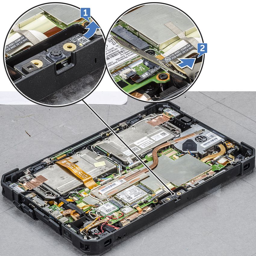
Contents

Chapter 1: Manipulación del equipo............................................................................................... 6
  Safety instructions.............................................................................................................................................................. 6
  Before working inside your computer.............................................................................................................................6
  Turning off your computertablet — Windows 10........................................................................................................ 7
  Después de manipular el interior del equipo.................................................................................................................. 7

Chapter 2: Extracción e instalación de componentes..................................................................... 8
  Herramientas recomendadas............................................................................................................................................ 8
  Screw size list.......................................................................................................................................................................8
  Batería.................................................................................................................................................................................... 9
     Removing the battery................................................................................................................................................... 9
     Removing the battery when the cross strap is attached - Optional............................................................... 12
     Instalación de la batería.............................................................................................................................................. 13
  Installing the battery when the cross strap is attached - Optional....................................................................... 14
  Tarjeta del módulo de identidad de suscripciones (SIM)..........................................................................................14
     Removing uSIM.............................................................................................................................................................14
     Inserción de la uSIM.................................................................................................................................................... 15
  Ensamblaje de la pantalla................................................................................................................................................. 15
     Removing display assembly....................................................................................................................................... 15
     Installing display assembly..........................................................................................................................................19
  Lápiz..................................................................................................................................................................................... 20
     Removing stylus...........................................................................................................................................................20
     Instalación del lápiz digital......................................................................................................................................... 20
  Tarjeta WLAN......................................................................................................................................................................21
     Removing WLAN card................................................................................................................................................. 21
     Instalación de la tarjeta WLAN................................................................................................................................. 22
  Tarjeta WWAN................................................................................................................................................................... 22
     Removing WWAN card...............................................................................................................................................22
     Instalación de la tarjeta WWAN............................................................................................................................... 23
  Batería CMOS.................................................................................................................................................................... 23
     Removing CMOS battery.......................................................................................................................................... 23
     Installing CMOS battery.............................................................................................................................................24
  Ensamblaje del botón de encendido..............................................................................................................................25
     Removing power button assembly.......................................................................................................................... 25
     Installing power button assembly............................................................................................................................ 26
  Micropuerto serie y puerto del conector de alimentación....................................................................................... 27
     Removing micro serial port and power connector port......................................................................................27
     Installing micro serial port and power connector port........................................................................................29
  Cámara frontal................................................................................................................................................................... 29
     Removing front camera............................................................................................................................................. 29
     Installing front camera................................................................................................................................................32
  Micrófono............................................................................................................................................................................ 33
     Removing microphone................................................................................................................................................33
     Installing microphone.................................................................................................................................................. 34

                                                                                                                                                                 Contents                   3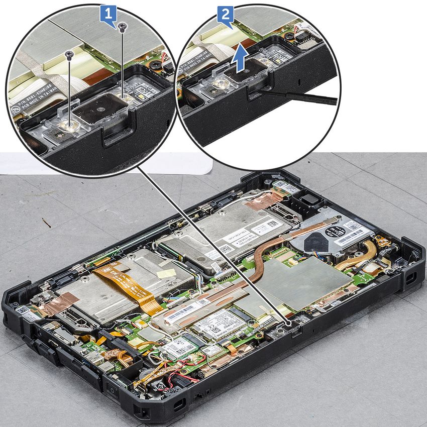
Heat sink for SSD..............................................................................................................................................................34
            Removing heatsink for SSD or PCIE.......................................................................................................................34
            Installing heatsink for SSD or PCIE.........................................................................................................................35
         Unidad de estado sólido (SSD) PCIe............................................................................................................................ 35
            Removing PCIe Solid State Drive - SSD................................................................................................................ 35
            Installing PCIe Solid State Drive - SSD.................................................................................................................. 36
         Ventilador del sistema...................................................................................................................................................... 37
            Removing system fan................................................................................................................................................. 37
            Installing system fan................................................................................................................................................... 37
         Placa base........................................................................................................................................................................... 38
            Removing system board............................................................................................................................................ 38
            Installing system board...............................................................................................................................................44
         Docking Board.................................................................................................................................................................... 44
            Removing docking board........................................................................................................................................... 44
            Installing docking board............................................................................................................................................. 45
         Back Camera...................................................................................................................................................................... 46
            Removing back camera.............................................................................................................................................. 46
            Installing back camera................................................................................................................................................ 47
         Smartcard holder...............................................................................................................................................................48
            Removing smartcard holder...................................................................................................................................... 48
            Installing smartcard holder........................................................................................................................................50
         Bottom base assembly..................................................................................................................................................... 50
            Removing bottom base assembly............................................................................................................................50
            Installing bottom base assembly.............................................................................................................................. 52

    Chapter 3: Tecnología y componentes......................................................................................... 53
      Adaptador de alimentación............................................................................................................................................. 53
      USB features...................................................................................................................................................................... 53
      Funciones de la memoria................................................................................................................................................. 55

    Chapter 4: Software....................................................................................................................56
      Sistemas operativos compatibles.................................................................................................................................. 56
      Downloading drivers......................................................................................................................................................... 56
      Intel audio drivers.............................................................................................................................................................. 57
      Intel chipset drivers.......................................................................................................................................................... 57
      Intel HD Graphics drivers.................................................................................................................................................57
      Network drivers................................................................................................................................................................. 58
      System devices drivers.................................................................................................................................................... 58
      Storage drivers.................................................................................................................................................................. 58

    Chapter 5: Especificaciones del sistema......................................................................................60
      Visión general del producto............................................................................................................................................ 60
         Funciones principales................................................................................................................................................. 60
      Power and battery-status light......................................................................................................................................60
      Especificaciones del sistema........................................................................................................................................... 61
      Especificaciones del procesador.................................................................................................................................... 61
      Especificaciones de la memoria...................................................................................................................................... 61
      Especificaciones de almacenamiento............................................................................................................................ 61
      Audio specifications...........................................................................................................................................................61

4   Contents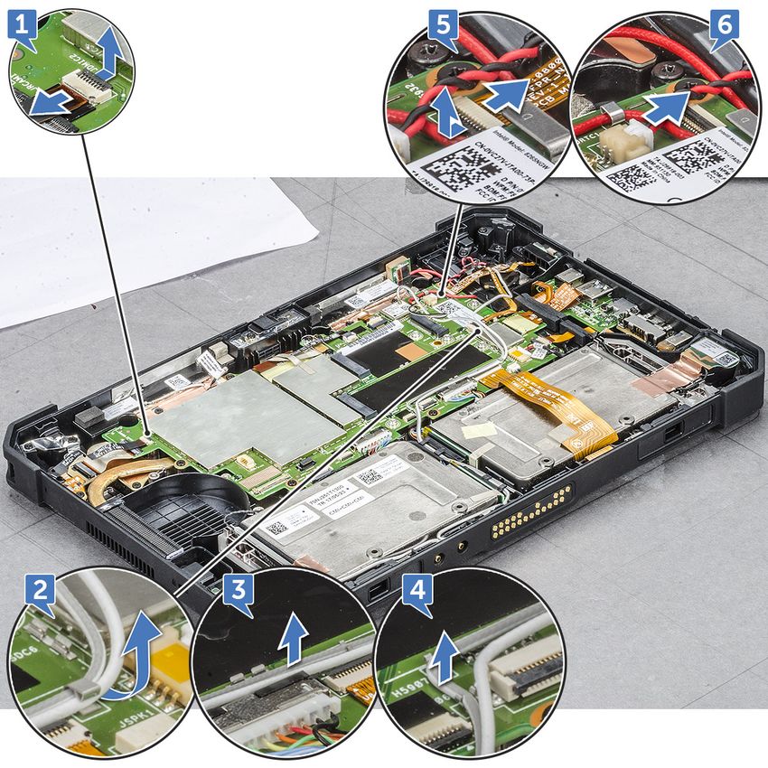
Especificaciones de vídeo............................................................................................................................................... 62
     Camera specifications...................................................................................................................................................... 62
     Especificaciones de comunicación................................................................................................................................ 62
     Especificaciones de puertos y conectores..................................................................................................................63
     Especificaciones de la pantalla.......................................................................................................................................63
     Especificaciones de toque...............................................................................................................................................64
     Adapter specifications......................................................................................................................................................64
     Especificaciones de las dimensiones físicas................................................................................................................65
     Especificaciones ambientales......................................................................................................................................... 65

Chapter 6: System Setup (Configuración del sistema)................................................................ 66
  Secuencia de inicio............................................................................................................................................................66
  Teclas de navegación....................................................................................................................................................... 66
  Descripción general del programa de configuración del sistema........................................................................... 67
     Opciones de la pantalla General (General)............................................................................................................ 67
     Opciones de la pantalla System Configuration (Configuración del sistema)................................................ 68
     Opciones de la pantalla Video (Vídeo)....................................................................................................................70
     Opciones de la pantalla Security (Seguridad).......................................................................................................70
     Inicio seguro.................................................................................................................................................................. 72
     Extensiones Intel software Guard............................................................................................................................72
     Opciones de la pantalla Performance (Rendimiento)......................................................................................... 72
     Administración de alimentación................................................................................................................................ 73
     Comportamiento durante la POST.......................................................................................................................... 74
     Capacidad de administración.................................................................................................................................... 75
     Opciones de Compatibilidad con la virtualización................................................................................................ 76
     Opciones de modo inalámbrico.................................................................................................................................76
     Mantenimiento............................................................................................................................................................. 76
     System Log (Registro del sistema)......................................................................................................................... 77
     Resolución del sistema SupportAssist.................................................................................................................... 77

Chapter 7: Solución de problemas................................................................................................78
  Dell Enhanced Pre-Boot System Assessment - ePSA diagnostic 3.0.................................................................. 78
  Diagnostic LED................................................................................................................................................................... 78
  Solución de problemas generales...................................................................................................................................79

Chapter 8: Accesorios del ecosistema.......................................................................................... 81
  Active Stylus....................................................................................................................................................................... 81
  Getting the stylus ready for use.....................................................................................................................................81
  Setting the Stylus Mode..................................................................................................................................................82
  Vista inferior del sistema................................................................................................................................................. 83
  System right view............................................................................................................................................................. 84
  Dock front view................................................................................................................................................................. 84
  Keyboard Dock ..................................................................................................................................................................85
     Turn the Backlight On - Off and Adjust Brightness ...........................................................................................85
     Keyboard Function - Fn Key Lock ..........................................................................................................................86
  Dock rear view................................................................................................................................................................... 86
  Input Output module.........................................................................................................................................................87
  Rugged tablet vehicle dock.............................................................................................................................................87

                                                                                                                                                            Contents                  5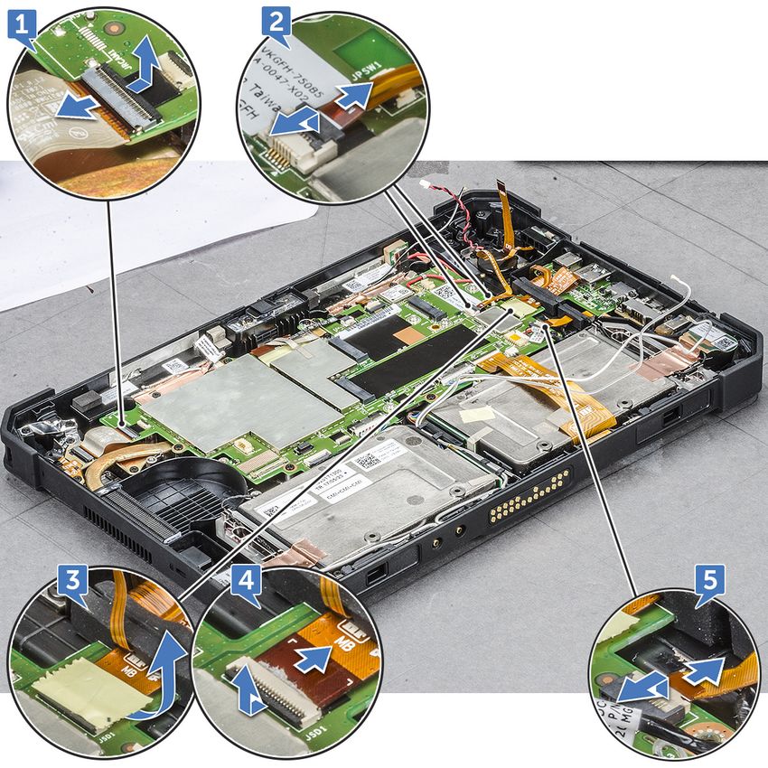
1
                                                            Manipulación del equipo
Temas:
•   Safety instructions
•   Before working inside your computer
•   Turning off your computertablet — Windows 10
•   Después de manipular el interior del equipo

Safety instructions
Use the following safety guidelines to protect your computer from potential damage and to ensure your personal safety. Unless
otherwise noted, each procedure included in this document assumes that the following conditions exist:
● You have read the safety information that shipped with your computer.
● A component can be replaced or, if purchased separately, installed by performing the removal procedure in the reverse
  order.
   NOTE: Disconnect all power sources before opening the computer cover or panels. After you finish working inside the
   computer, replace all covers, panels, and screws before connecting to the power source.

    NOTE: Before working inside your computer, read the safety information that shipped with your computer. For additional
    safety best practices information, see the Regulatory Compliance Homepage at www.dell.com/regulatory_compliance

    CAUTION: Many repairs may only be done by a certified service technician. You should only perform
    troubleshooting and simple repairs as authorized in your product documentation, or as directed by the online or
    telephone service and support team. Damage due to servicing that is not authorized by Dell is not covered by
    your warranty. Read and follow the safety instructions that came with the product.

    CAUTION: To avoid electrostatic discharge, ground yourself by using a wrist grounding strap or by periodically
    touching an unpainted metal surface that is grounded to ground yourself before you touch the computer to
    perform any disassembly tasks.

    CAUTION: Handle components and cards with care. Do not touch the components or contacts on a card. Hold a
    card by its edges or by its metal mounting bracket. Hold a component such as a processor by its edges, not by
    its pins.

    CAUTION: When you disconnect a cable, pull on its connector or on its pull-tab, not on the cable itself. Some
    cables have connectors with locking tabs; if you are disconnecting this type of cable, press in on the locking
    tabs before you disconnect the cable. As you pull connectors apart, keep them evenly aligned to avoid bending
    any connector pins. Also, before you connect a cable, ensure that both connectors are correctly oriented and
    aligned.

    NOTE: The color of your computer and certain components may appear differently than shown in this document.

Before working inside your computer
To avoid damaging your computer, perform the following steps before you begin working inside the computer.
1. Ensure that you follow the Safety instruction.
2. Ensure that your work surface is flat and clean to prevent the computer cover from being scratched.
3. Turn off your computer.
4. If the computer is connected to a docking device (docked) such as the optional Media Base or Battery Slice, undock it.

6       Manipulación del equipo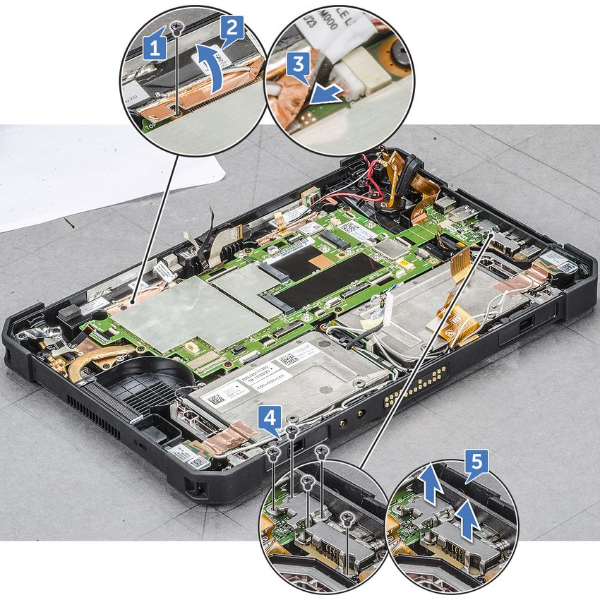
CAUTION: To disconnect a network cable, first unplug the cable from your computer and then unplug the
        cable from the network device.

5. Disconnect all network cables from the computer.
6. Disconnect your computer and all attached devices from their electrical outlets.
7. Turn the computer upside-down on a flat work surface.
        NOTE: Ensure to close the display if the system is a laptop. To avoid damaging the system board, remove the main
        battery before you service the computer.

8. Remove the main battery.
9. Turn the computer top-side up.
        NOTE: Open the display if the system is a laptop.

10. Press the power button to ground the system board.
        CAUTION: Before touching anything inside your computer, ground yourself by touching an unpainted metal
        surface, such as the metal at the back of the computer. While you work, periodically touch an unpainted
        metal surface to dissipate static electricity, which could harm internal components.

11. Remove any installed ExpressCards or Smart Cards from the appropriate slots.

Turning off your computertablet — Windows 10
    PRECAUCIÓN: To avoid losing data, save and close all open files and exit all open programs before you turn off
    your computer or remove the side cover.

1. Click or tap       .

2. Click or tap     and then click or tap Shut down.
        NOTA: Ensure that the computer and all attached devices are turned off. If your computer and attached devices did not
        automatically turn off when you shut down your operating system, press and hold the power button for about 6 seconds
        to turn them off.

Después de manipular el interior del equipo
Una vez finalizado el procedimiento de instalación, asegúrese de conectar los dispositivos externos, las tarjetas y los cables
antes de encender el equipo.
    PRECAUCIÓN: Para evitar daños en la computadora, utilice únicamente la batería diseñada específicamente para
    esta computadora Dell. No utilice baterías diseñadas para otros equipos Dell.
1. Conecte los dispositivos externos, como un replicador de puerto o la base para medios y vuelva a colocar las tarjetas, como
   una tarjeta ExpressCard.
2. Conecte los cables telefónicos o de red al equipo.
        PRECAUCIÓN: Para conectar un cable de red, enchúfelo primero en el dispositivo de red y, después, en el
        equipo.

3. Conecte el equipo y todos los dispositivos conectados a la toma eléctrica.
4. Encienda el equipo.

                                                                                                Manipulación del equipo          7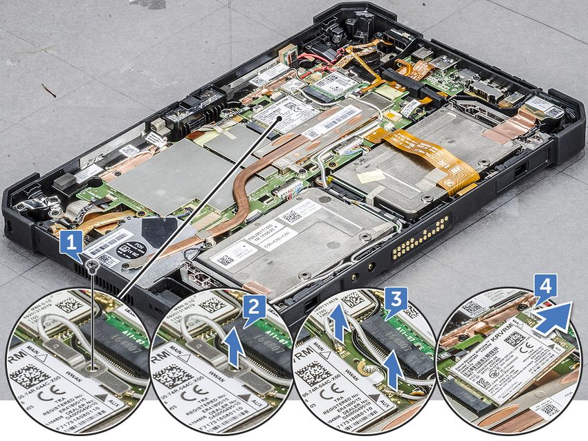
2
                 Extracción e instalación de componentes
Esta sección ofrece información detallada sobre cómo extraer o instalar los componentes de su equipo.
Temas:
•      Herramientas recomendadas
•      Screw size list
•      Batería
•      Installing the battery when the cross strap is attached - Optional
•      Tarjeta del módulo de identidad de suscripciones (SIM)
•      Ensamblaje de la pantalla
•      Lápiz
•      Tarjeta WLAN
•      Tarjeta WWAN
•      Batería CMOS
•      Ensamblaje del botón de encendido
•      Micropuerto serie y puerto del conector de alimentación
•      Cámara frontal
•      Micrófono
•      Heat sink for SSD
•      Unidad de estado sólido (SSD) PCIe
•      Ventilador del sistema
•      Placa base
•      Docking Board
•      Back Camera
•      Smartcard holder
•      Bottom base assembly

Herramientas recomendadas
Los procedimientos de este documento requieren el uso de las siguientes herramientas:
● Destornillador Phillips núm. 0
● Destornillador Phillips núm. 1
● Punta trazadora de plástico DSP estándar

Screw size list
Table 1. Latitude 7212 Rugged Extreme Tablet screw size list
    Componen         M2*2         M2*2.5          M2*3           M2*4       M2*5        M2.5*3          M2.5*5   M2.5*8
       t
    Smart card         6
    Bottom
                       6                            81                                                    19
    Base
    Front
                                                                             2
    Camera
    Rear
                                                                             3
    Camera

8            Extracción e instalación de componentes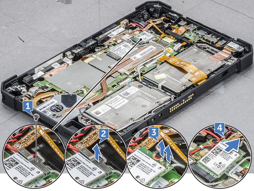
Table 1. Latitude 7212 Rugged Extreme Tablet screw size list
 Componen         M2*2          M2*2.5          M2*3          M2*4           M2*5            M2.5*3   M2.5*5     M2.5*8
    t
Protective
Rubber
Bumper( all                                                                                                            8
four
corners)
WLAN                                              1
WWAN                                              1
M.2 SSD                                           1
System
Board
Assembly
                                                                               14
(System
Board and
Fan)
Power
Button                              1
Assembly
DC-In Cable
                                                                                3
and Bracket
Kensington
Lock                                              3
Bracket
LCD Bezel                                                                                               19
Bracket
                                                  1
Docking

Batería
Removing the battery
    WARNING: Using an incompatible battery may increase the risk of fire or explosion. Replace the battery only
    with a compatible battery purchased from Dell. The battery is designed to work with your Dell Tablet. Do not use
    a battery from any other computer with your tablet.

    WARNING: Before removing or replacing the battery, turn off the computer, disconnect the AC adapter from
    the electrical outlet and the tablet, and remove any other external cables from the tablet.
1. Follow the procedure in Before Working Inside Your Computer.
2. Locate the battery and slide the battery latch to unlock the battery release latch [1].
3. Push the button in a downward direction to release the battery [2].

                                                                             Extracción e instalación de componentes       9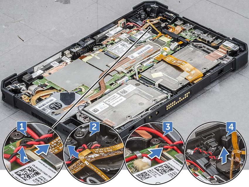
The battery is released from the battery bay.
4. Lift the edge of the battery that pops up.

10        Extracción e instalación de componentes
Extracción e instalación de componentes 11
Removing the battery when the cross strap is attached - Optional
     WARNING: Using an incompatible battery may increase the risk of fire or explosion. Replace the battery only
     with a compatible battery purchased from Dell. The battery is designed to work with your Dell Tablet. Do not use
     a battery from any other computer with your tablet.

     WARNING: Before removing or replacing the battery, turn off the computer, disconnect the AC adapter from
     the electrical outlet and the tablet, and remove any other external cables from the tablet.
1. Follow the procedure in Before Working Inside Your Computer.
2. Peel off the velcro strap.

3. Slide the strap and release the strap from the holder to access the battery latch.

4. Slide the battery latch to unlock the battery release latch and then push the latch in a downward direction to release the
   battery.

12      Extracción e instalación de componentes
The battery is released from the battery bay.
5. Lift the edge of the battery that pops up to release the battery.
Instalación de la batería
1. Inserte la batería en su ranura.
NOTA: Asegúrese de que la pata de metal de la batería esté alineada en su lugar.
2. Deslice la batería en su ranura hasta que encaje en su lugar.
3. Asegúrese de que el pestillo de la batería esté de nuevo en estado bloqueado.
NOTA: Hay dos baterías. Realice los pasos del 1 al 3 para instalar la batería 1 y la batería 2 en la tableta.
4. Siga los procedimientos que se describen en Después de manipular el interior del equipo.
Extracción e instalación de componentes 13Installing the battery when the cross strap is attached
- Optional
1. Insert the battery into the battery slot.
2. Slide the battery into the slot until it clicks into place and locked.
3. Slide the velcro strap into the strap holder.
4. Affix the velcro strap.
5. Follow the procedure in After working inside your computer.
Tarjeta del módulo de identidad de suscripciones
(SIM)
Removing uSIM
1. Follow the procedure in Before working inside your computer.
2. Remove the left battery.
3. Lift the latch [1] and pull the SIM slot cap [2].
4. Pull the SIM from the slot until it is released [3].
NOTE: Use a flat pointed scribe to ease removing the SIM.
5. Press the SIM slot cap to initial state.
6. Install the:
a. Left battery
14 Extracción e instalación de componentesInserción de la uSIM
1. Extraiga la batería izquierda.
2. Para insertar el uSIM:
a. Levante el pestillo y extraiga la tapa de la ranura para tarjeta SIM.
b. Inserte la tarjeta SIM en la ranura hasta que está bloqueada.
NOTA: Asegúrese de que el chip dorado esté orientado hacia abajo en la ranura.
c. Presione la tapa de la ranura para tarjeta SIM hasta que alcance el estado inicial.
3. Siga los procedimientos que se describen en Después de manipular el interior del equipo.
Ensamblaje de la pantalla
Removing display assembly
1. Follow the procedure in Before working inside your computer.
2. Remove the:
a. Battery
3. To remove the display assembly (with plastic scribe):
a. Place the display side of system on a smooth flat surface.
b. Remove the screws (19) that secures the display panel to the tablet.
4. Flip the system so that the display assembly is at top view.
Extracción e instalación de componentes 155. Insert a plastic scribe near the Windows button [1].
NOTE: Pointed tip of the plastic scribe should be inserted to avoid damage to the seal on the LCD and to the clips that
secure the LCD display to the tablet chassis.
6. Pry the edges starting from Windows button clockwise [1,2].
NOTE: Gently pry the edges evenly to unlock the plastic clips that secures the display assembly to the tablet chassis.
7. Lift the display assembly [1] by angle 15° and slide it from the chassis [2].
16 Extracción e instalación de componentes8. Flip the display assembly by an angle less than 90°.
NOTE: Ensure not to flip more than 90° angle, as the display assembly ports and cables are connected to the system
board and may damage the display cables.
9. Before removing display assembly:
a. Place the bottom edge of the display panel inside the bottom edge of the rear chassis.
b. Flip open the display panel to 90° angle and lay it angled on the tablet chassis.
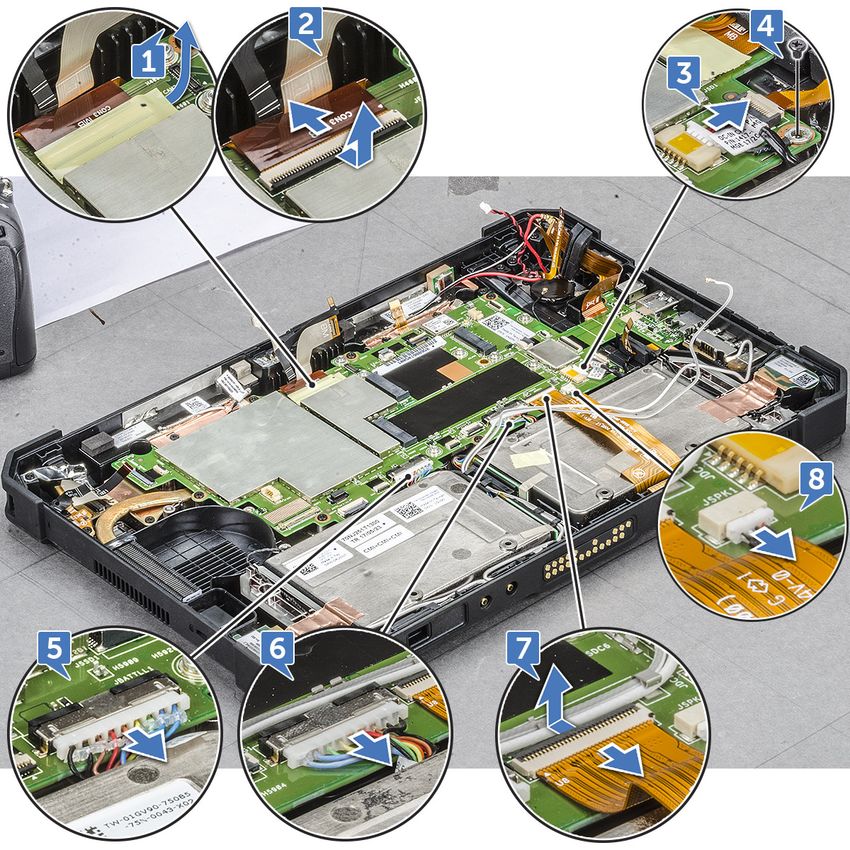
10. To disconnect the display cable:
Extracción e instalación de componentes 17a. Remove the adhesive tape that secures the LVDS cable on the system board [1].
b. Lift the latch with a plastic scribe on the system board.
c. Disconnect the connector of LVDS cable from the slot by a plastic scribe [2] and remove the cable [3].
d. Remove the adhesive tape that secures the Function Key cable on the system board [4].
e. Lift the latch by a plastic scribe and release the Touch cable connected to the system board [5].
NOTE: Disconnect only the display cable from the system board. NEVER disconnect the display cable from the display
panel.
11. Remove the display assembly from the tablet.
18 Extracción e instalación de componentesNOTE: DO NOT remove any cable or adhesive tape from the display panel, unless you are replacing the cables
separately.
Installing display assembly
1. Place the system chassis on a plane surface.
2. Place the bottom edge of the display assembly inside the bottom edge of the rear chassis.
3. Rest the display assembly by less than 90° angle.
NOTE: Use a support to attain the required angle.
4. Connect the touch cable, function keys cable, and LVDS cable to the connector on the system board.
5. Release the latch to secure the cables to the respective connecting ports.
NOTE: Make sure to insert the cable under the clips, if not, the system may not display video after reassembling.
6. Paste the adhesive tapes to secure the connected slots.
NOTE: Ensure to secure the adhesive tapes, to protect the display assembly from electrostatic discharge damage.
7. Align the display assembly on the tablet chassis and press the edges to snap-in.
NOTE:
● Ensure that the Window button on the display assembly aligns with the docking pogo pins on the system
board chassis.
● Press the edges starting from Windows button clockwise until they snap-in evenly from all sides. Ensure
to hear a click sound when the display assembly is aligned in correct position.
8. Flip the system so that the battery is at top view.
NOTE: Ensure to place the system in a flat surface.
9. Replace the screws (19) to secure the display assembly to the tablet.
Extracción e instalación de componentes 19NOTE: DO NOT tighten the screws too much, to avoid damage the screws thread.
10. Install the:
a. Battery
11. Follow the procedure in After working inside your computer.
Lápiz
Removing stylus
1. Follow the procedure in Before working inside your computer.
2. Locate the stylus at the top of the tablet.
3. Pull the stylus by the thread upward.
NOTE: Avoid pulling the stylus attached with the stretchable thread.
4. Pull the stylus from the groove on the tablet.
NOTE: Pull the stylus until the tip of the pen is visible at the mouth of the groove.
The stylus is ready to assist you in using the rugged tablet.
For more details, see Getting the stylus ready for use
Instalación del lápiz digital
1. Alinee el lápiz digital con la ranura de la tableta.
2. Presione y deslice con suavidad para asegurar el lápiz digital.
20 Extracción e instalación de componentesNOTA: Evite colgar el lápiz digital separado de su ranura cuando no lo utilice.
3. Siga los procedimientos que se describen en Después de manipular el interior del equipo.
Tarjeta WLAN
Removing WLAN card
1. Follow the procedure in Before working inside your computer.
2. Remove the:
a. Battery
b. Display assembly
3. To remove the WLAN card:
a. Place the back side of system on a flat surface.
b. Locate the WLAN card.
c. Remove the screw that secures the WLAN bracket to the system board [1].
d. Lift the metal bracket [2] from the WLAN card.
e. Disconnect the two antenna cables [3] with a plastic scribe.
NOTE: Insert the edge of the plastic scribe between the tiny gap of cable copper head and WLAN card button pin.
f. Slide and lift the WLAN card from the slot on the system board [4].
NOTE: Ensure to lift the WLAN card by NOT more than 35° angle.
CAUTION: Never touch the metal pins or the circuit with bare hands. Touch at the side of the WLAN card.
Extracción e instalación de componentes 21Instalación de la tarjeta WLAN
1. Inserte la tarjeta WLAN en la ranura de la placa base.
NOTA: Asegúrese de que la pata de metal esté hacia abajo hacia la ranura de la placa base y que se mantenga un ángulo
INFERIOR a 30°.
2. Conecte los cables WLAN a los conectores de la tarjeta WLAN.
NOTA: Asegúrese de que los cables estén alineados hacia arriba y presione suavemente en la parte superior para que a
la cabeza de cobre del cable encaje en la pata del botón de la tarjeta WLAN.
3. Para fijar la tarjeta WLAN, coloque el soporte de la antena soporte y ajuste el tornillo M2.0 x 3.0.
4. Coloque:
a. Ensamblaje de la pantalla
b. Batería
5. Siga los procedimientos que se describen en Después de manipular el interior del equipo.
Tarjeta WWAN
Removing WWAN card
1. Follow the procedure in Before working inside your computer.
2. Remove the:
a. Battery
b. Display assembly
3. To remove the WWAN card:
a. Place the back side of system on a flat surface.
b. Locate the WWAN card.
c. Remove the screw that secures the WWAN bracket to the system board [1].
d. Lift the metal bracket [2] from the system board.
e. Disconnect main and auxiliary cables [3] with a plastic scribe from the connector on the WWAN card.
NOTE: Insert the edge of the plastic scribe between the tiny gap of cable copper head and WWAN card button pin.
f. Slide and lift the WWAN card from the slot on the system board [4].
NOTE: Ensure to lift the WWAN card by an angle NOT more than 35°.
CAUTION: Never touch the metal pins or the circuit with bare hands. Touch at the side of the WWAN
card.
22 Extracción e instalación de componentesInstalación de la tarjeta WWAN
1. Inserte la tarjeta WWAN en la ranura de la placa base.
NOTA: Asegúrese de que la pata de metal esté hacia abajo hacia la ranura de la placa base.
2. Conecte los cables de la tarjeta WWAN a los conectores de la tarjeta WWAN.
NOTA: El número IMEI se ve en la tarjeta WWAN.
3. Para fijar la tarjeta WWAN, coloque el soporte de metal y apriete el tornillo M2.0 x 3.0.
4. Coloque:
a. Ensamblaje de la pantalla
b. Batería
5. Siga los procedimientos que se describen en Después de manipular el interior del equipo.
Batería CMOS
Removing CMOS battery
1. Follow the procedure in Before working inside your computer.
2. Remove the:
a. Battery
b. Display assembly
3. To remove the CMOS battery:
a. Place the back side of system on a flat surface.
Extracción e instalación de componentes 23b. Locate the CMOS battery.
c. Lift the fingerprint reader cable latch by a plastic scribe and push the cable gently from the latch [1].
NOTE: Ensure to unlock the fingerprint reader cable to release the CMOS battery.
d. Remove the CMOS cable from the routing clip on the system board [2].
e. Push the pin connected to the system board CMOS slot by a plastic scribe [3].
NOTE: Push the cable pin head with a plastic scribe at an angle not more than 30°. DO NOT push too hard, as it
may damage the cable pin head.
f. Lift the CMOS battery from the adhesive tape [4].
NOTE: Ensure not to pull the CMOS battery upwards as it is positioned beneath the fingerprint reader cable. Gently
release the battery from the adhesive tape.
NOTE: Replace the CMOS battery when checksum error is displayed in booting.
Installing CMOS battery
1. Align the CMOS battery over the rubber pad on top of the fingerprint reader.
2. Press the CMOS battery on the adhesive tape.
NOTE: CMOS battery for the tablet is insulated in a protective shield. To avoid poor connection of the wire with
battery, NEVER tear the protective shield.
3. Connect the CMOS battery cable to the slot on the system board.
4. Slide the fingerprint reader cable beneath the latch and close the latch.
NOTE: Install the CMOS battery cable, and then connect the fingerprint reader cable.
5. Install the:
24 Extracción e instalación de componentesa. Display assembly
b. Battery
6. Follow the procedure in After working inside your computer.
Ensamblaje del botón de encendido
Removing power button assembly
1. Follow the procedure in Before working inside your computer.
2. Remove the:
a. Battery
b. Display assembly
3. To remove the power button assembly:
a. Place the back side of system on a flat surface.
b. Locate the power button assembly.
c. Lift the latch by an angle 35° to unlock and gently release the power button assembly cable [1].
d. Remove the screw (1) that secures the power button assembly to the system board [2].
NOTE: DO NOT try to remove the power assembly without removing the screw.
e. Push with plastic scribe, and pull the power button bracket [3].
Extracción e instalación de componentes 25NOTE: Power button assembly bus cable is routed between the square gap in the power button bracket.
f. Release the adhesive tape that secures the power button assembly.
g. Push and release the power button assembly from the chassis by a plastic scribe [4].
h. Lift and remove the power button bracket together with the power button assembly.
NOTE: Power button is encapsulated within a power button bracket.
Installing power button assembly
1. Assemble the power assembly button with the power button bracket.
NOTE: Ensure that the power button cable is routed between the square gap in the power button bracket.
2. Push the power button assembly in the slot on the tablet chassis.
NOTE: Ensure NOT to insert the power button from the exterior right view.
3. Secure the power button assembly with the adhesive tape.
4. Replace the screw to secure the power button assembly to the tablet chassis.
5. Connect the power button assembly cable, and close the latch on the system board.
26 Extracción e instalación de componentes6. Install the:
a. Display assembly
b. Battery
7. Follow the procedure in After working inside your computer.
Micropuerto serie y puerto del conector de
alimentación
Removing micro serial port and power connector port
1. Follow the procedure in Before working inside your computer.
2. Remove the:
a. Battery
b. Display assembly
3. To remove the micro serial port and power connector port:
a. Place the back side of system on a flat surface.
b. Locate the micro serial port and power connector port.
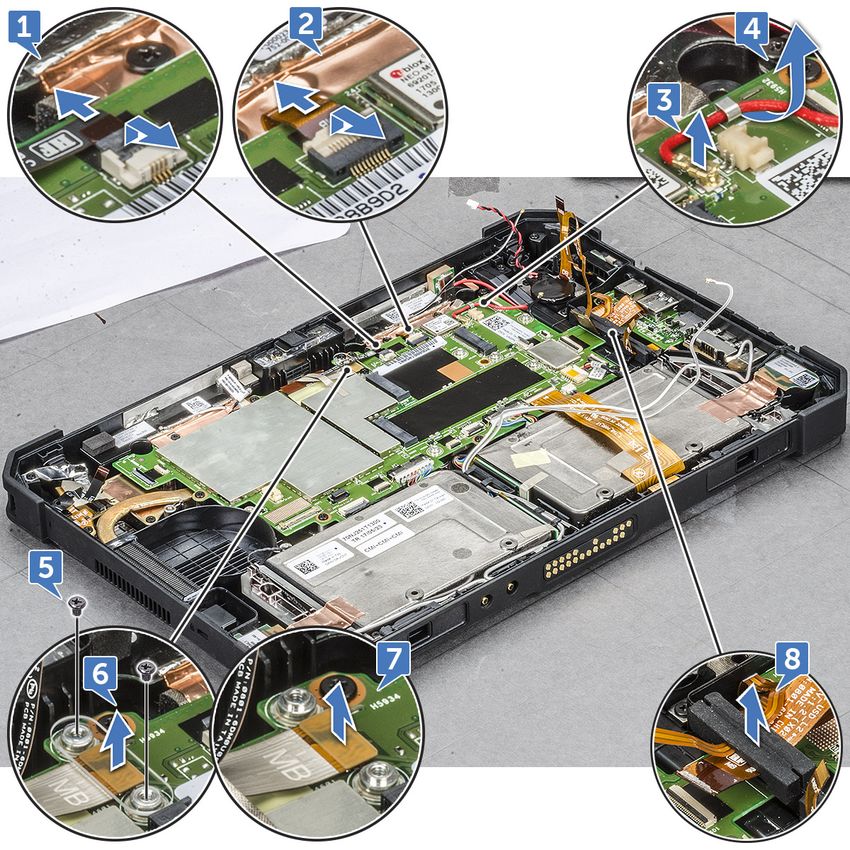
c. Push to disconnect the power connecter cable [1] and remove the screw that secures power connector cable to the
system board [2].
d. Lift the latch and disconnect the micro serial port cable from the connector [3].
e. Lift the rubber bracket upward that secures the cable with system chassis [4].
NOTE: Ensure to release the bracket, after the micro serial port cable is connected.
f. Remove the metal bracket screws (5) that secure the micro serial port and USB-C port to the system chassis [5].
NOTE: Ensure to remove USB-C bracket in order to remove the micro serial port.
g. Lift the micro serial port bracket first, then the USB-C port bracket from the system [6].
h. Lift the micro serial port and power connector port on the system board [7].
NOTE: The micro serial port is still attached to the power connector port, lift only enough to set it aside in order to
remove the power connector port screw
i. Remove the screw (1) that secures the power connector port and lift the power connector port along with the micro
serial port from the system board [8,9].
Extracción e instalación de componentes 27Power connector port and micro serial port are assembled as one single component to connect on the tablet system board.
NOTE: Malfunction of either component requires to remove both power connector port and micro serial port.
28 Extracción e instalación de componentesInstalling micro serial port and power connector port
1. Insert the power connector port and micro serial port into the slot on the chassis.
2. Align the metal brackets that secure the ports on the system chassis.
NOTE: The USB-C port bracket is followed by the micro serial port bracket, as the micro serial port bracket sits on top
of the USB-C port bracket with screw (1).
3. Replace the screws (5) to secure the micro serial port and power connector port to the chassis.
4. Align the rubber bracket and push to slide in the channel .
NOTE: Rubber bracket ensures to secure the micro serial port cable from damage.
5. Insert the micro serial port cable into the connector.
6. Close the latch to secure the micro serial port cable to the system board.
7. Align the power connector port cable to the system board and affix the ground wire with the screw (1) to the system board.
8. Install the:
a. Display assembly
b. Battery
9. Follow the procedure in After working inside your computer.
Cámara frontal
Removing front camera
1. Follow the procedure in Before working inside your computer.
2. Remove the:
a. Battery
b. Display assembly
3. To remove the front camera:
a. Place the back side of system on a flat surface.
b. Locate the front camera.
c. Slide the camera shutter towards right, to bring the lens cover is in the open position [1].
d. Insert the edge of the plastic scribe between the gap of lens shutter and lift camera lens shutter [2].
Extracción e instalación de componentes 29e. Remove the screws (2) that secure the camera on the system chassis [1].
f. Lift the lens case at the edge to insert the plastic scribe in the gap and lift the lens case by an angle not more than 35°
and push upward to release the camera lens case [2].
30 Extracción e instalación de componentesg. Flip the camera circuit board with a plastic scribe [1].
h. Disconnect the camera cable that secures the cable to the system board [2].
Extracción e instalación de componentes 31Installing front camera
1. Align the front camera circuit board over the camera chassis.
NOTE: Opposite side of the camera circuit board is placed to connect cable in the connector.
2. Connect the front camera cable and plug in the cable to the connector.
3. Flip the front camera circuit board, and align front camera circuit board with screw hole.
4. Align the camera lens case to the camera placeholder.
5. Replace the screw to secure the front camera circuit board on the system board.
6. Slide the lens shutter in the lens channel and push towards left.
7. Install the:
a. Display assembly
b. Battery
8. Follow the procedure in After working inside your computer.
32 Extracción e instalación de componentesMicrófono
Removing microphone
1. Follow the procedure in Before working inside your computer.
2. Remove the:
a. Battery
b. Display assembly
3. To remove the microphone:
a. Place the back side of system on a flat surface.
b. Locate the microphone.
c. Lift the latch and gently release the power microphone cable [1].
d. Remove the screws (2) that secures the integrated microphone assembly circuit board and microphone bracket that hold
the microphone to the system board [2].
NOTE: Ensure to remove the screw of the bracket which hold the microphone when the microphone circuit board is
aligned. Non-removal of the bracket can damage the rubber seal.
e. Release the microphone assembly and, lift the microphone form the tablet chassis [3].
Extracción e instalación de componentes 33NOTE: NEVER pull the microphone by the cable. In case the circuit board is not released smoothly, push from below
the microphone circuit board by a plastic scribe.
Installing microphone
1. Align the microphone system board on the tablet chassis.
2. Align the microphone input in the slot on the chassis, with the microphone input against the tablet chassis
3. Replace the bracket behind and against the microphone input and replace the screw (1) in the bracket to secure the
microphone to the tablet chassis.
4. Align the microphone IC board on the chassis and replace the screw (1) to secure the IC board to the chassis.
5. Slide the microphone bus cable in the port on system board and close the latch to secure the cable.
6. Install the:
a. Display assembly
b. Battery
7. Follow the procedure in After working inside your computer.
Heat sink for SSD
Removing heatsink for SSD or PCIE
1. Follow the procedure in Before working inside your computer.
2. Remove the:
a. Battery
b. Display assembly
3. To remove the heatsink:
a. Place the back side of system on a flat surface.
b. Locate the heatsink.
c. Remove the screws (4) securing the heatsink on the system board [1].
d. Lift the heat sink from the outlet connected on the heatsink fan and the system board [2].
NOTE: The thermal pad attached to the heatsink stick to the fan and SSD. Applying strong force can bend the
heatsink while lifting the heatsink from the system.
34 Extracción e instalación de componentesCAUTION: When the system has been on or in use, the surface of the heat sink may be hot. Ensure to lift
the heat sink cautiously when the heatsink cools.
CAUTION: DO NOT bend or damage the copper heat sink tunnel. Any damage results in malfunction and
over heating of the tablet.
Installing heatsink for SSD or PCIE
1. Align the heatsink on the system board.
NOTE: Ensure the SSD card in connected in the slot on the system board.
NOTE: Do ensure thermal pad is applied in the heatsink and the heatsink is not damaged. If the heatsink is reused,
ensure not to damage while removal.
2. Replace the screws (4) to secure the heatsink to the tablet chassis.
3. Install the:
a. Display assembly
b. Battery
4. Follow the procedure in After working inside your computer.
Unidad de estado sólido (SSD) PCIe
Removing PCIe Solid State Drive - SSD
1. Follow the procedure in Before working inside your computer.
2. Remove the:
a. Battery
b. Display assembly
c. Heat sink
Extracción e instalación de componentes 353. To remove the SDD:
a. Place the back side of system on a flat surface.
b. Locate the SSD.
c. Remove the screws (1) that secures the SSD on the system board [1].
d. Slide and lift the SSD card from the connector on the system board [2].
NOTE: Ensure to lift the SSD card by an angle NOT more than 30°.
CAUTION: Lift the SSD card by the side. DO NOT touch the circuit.
Installing PCIe Solid State Drive - SSD
1. Slide and insert the SSD module in the connector on the system board.
NOTE: Ensure that the IC on the SSD module is positioned upward in the connector on the system board. Do ensure to
insert the SSD module by an angle not more than 30° to 35°.
2. Replace the screw (1) to secure the SSD module to the tablet chassis.
3. Install the:
a. Heat sink
b. Display assembly
c. Battery
4. Follow the procedure in After working inside your computer.
36 Extracción e instalación de componentesYou can also read