Apricus Solar Hot Water Systems - Technical Manual - www.apricus.com.au
←
→
Page content transcription
If your browser does not render page correctly, please read the page content below
Apricus Solar Hot Water Systems
          Technical Manual

       Version 2.0 - March 2014

        AA8.2.1.7.1-Apricus-Technical-Manual-V2.0

       www.apricus.com.au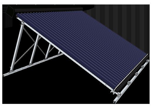
Apricus Solar Hot Water System - Technical Manual

  Apricus Technical Manual Table of Contents
  1. INTRODUCTION                                                                             4     5. INSTALLATION                                                                         15
      1.1 Foreword................................................................... 4               5.1 Mounting Frame System.......................................... 15
      1.2 Scope........................................................................ 4                 5.1.1 Installation Notes..........................................................15
      1.3 Terminology.............................................................. 4                     5.1.2 Installation – Assembly Guide.......................................15
                                                                                                          5.1.3 Installation - Roof Fixing Guide.....................................16
      1.4 Certification.............................................................. 5
                                                                                                          5.1.4 Tin Roof Installation Example:......................................16
      1.5 Conversions............................................................... 5                    5.1.5 Tiled Roof Installation Example:....................................16
                                                                                                          5.1.6 Adjusting Tilt Mount Angle:..........................................17
  2. WARNINGS AND PRECAUTIONS                                                                 5       5.2 Collector Manifold Connection................................. 17
      2.1 Installer Requirements .............................................. 5                         5.2.1 Silver Soldering/Brazing................................................17
      2.2 Occupational Health and Safety................................ 5                                5.2.2 Compression Fittings.....................................................17
      2.3 Over Pressure and Temperature Protection............... 5                                       5.2.3 Press Tools....................................................................17
          2.3.1 Pressure Temperature Relief...........................................5               5.3 Pump Station........................................................... 17
          2.3.2 Mains Pressure Control...................................................5                5.3.1 Installation Guide..........................................................17
      2.4 Water Quality............................................................ 6                     5.3.2 Flow Meter Settings......................................................17
      2.5 Legionella Control..................................................... 6                   5.4 Solar Differential Controller..................................... 17
      2.6 Weather Related Issues and Acts of God.................... 6                                    5.4.1 Controller Settings........................................................17
          2.6.1 Freeze Protection............................................................6            5.4.2 Temperature Sensors....................................................18
          2.6.2 Lightning Protection.......................................................6          5.5 Insulation................................................................ 18
          2.6.3 Hail Resistance ..............................................................6       5.6 System Filling and Air Purge.................................... 18
      2.7 Stagnation and No-Load Conditions.......................... 6                               5.7 Evacuated Tubes and Heat Pipes............................. 18
          2.7.1 Information on Stagnation.............................................6                   5.7.1 Installation Notes..........................................................18
          2.7.2 Hydrogen Build Up..........................................................7              5.7.2 Installation Guide..........................................................18
          2.7.3 Water Boiling Temperatures ..........................................7                5.8 Auxiliary Boosting Components............................... 19
                                                                                                          5.8.1 Electric Booster, Thermostat and Element Setup..........19
  3. INFORMATION FOR END-USER                                                                 8           5.8.2 Gas Booster Setup.........................................................19
      3.1 How Solar Heating Works.......................................... 8
          3.1.1 Introduction....................................................................8   6. POST INSTALLATION                                                                    19
          3.1.2 Summer and Winter Solar Heating.................................8                     6.1 Commissioning........................................................ 19
          3.1.3 How the Apricus System Works.......................................8                      6.1.1 System Operation Check...............................................19
      3.2 How Boosting Works................................................. 8                           6.1.2 Photo Records...............................................................19
          3.2.1 Boosting Explained.........................................................8              6.1.3 Installation Record Form...............................................19
          3.2.2 Legionella Bacteria - Importance of Boosting.................8                            6.1.4 Rebate Forms................................................................19
          3.2.3 Electric Boosted Systems.................................................8            6.2 Maintenance........................................................... 19
          3.2.4 Gas Boosted Systems......................................................8                6.2.1 Damaged Tubes............................................................20
      3.3 System Maintenance & Precautions........................... 9                                   6.2.3 Draining the System......................................................20
          3.3.1 System Maintenance.......................................................9                6.2.4 Over Pressure Protection Maintenance........................20
          3.3.2 Glass Lined Tank Precautions..........................................9                   6.2.5 Magnesium Anode Replacement..................................20
      3.4 End-User Troubleshooting Guide............................. 10

  4. PRE-INSTALLATION                                                                       11
      4.1 System Selection...................................................... 11
      4.2 Site Inspection......................................................... 11
          4.2.1 Collector Location.........................................................11
          4.2.2 Mounting Frame Location.............................................11
          4.2.3 Storage Tank Location...................................................12
      4.3 Transport and Unpacking ....................................... 12
          4.3.1 Transport of Components.............................................12
          4.3.2 Unpacking of Components............................................12
      4.4 Component Inspection............................................. 12
          4.4.1 Evacuated Tubes & Heat Pipes......................................12
          4.4.2 Pump Station Inspection...............................................12
          4.4.3 Mounting Frame System...............................................12

  Page 2 of 49                                  AA8.2.1.7.1-Apricus-Technical-Manual-V2.0                                                   Copyright © 2014 Apricus Australia Pty Ltd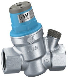
Apricus Solar Hot Water System - Technical Manual

  7. CUSTOM SYSTEM DESIGN GUIDELINES                                                        21
      7.1 Introduction............................................................ 21
          7.1.1 Associated Work...........................................................21
      7.2 Calculating Load...................................................... 21
          7.2.1 Calculating Water Usage..............................................21
          7.2.2 Calculating Energy Requirements.................................21
      7.3 System Sizing........................................................... 22
          7.3.1 Collector Size Requirement...........................................22
          7.3.2 Roof Space and Collector Shading................................22
          7.3.3 Storage Tank Sizing.......................................................22
          7.3.4 Pipe Material ...............................................................22
      7.4 System Type............................................................ 23
          7.4.1 Closed loop...................................................................23
          7.4.2 Open Loop or Direct Flow.............................................23
          7.4.3 Drainback......................................................................23
          7.4.4 Constant Use, 7 Days a Week.......................................23
          7.4.5 Constant Use, 5 Days a Week.......................................23
          7.4.6 Daily Peaks, 7 Days a Week..........................................23
          7.4.7 Constant Use, with Extended Periods of Non-Use.........24
      7.5 System Design and Configuration............................ 24
          7.5.1 Multiple Collector Connection.......................................24
          7.5.2 Balanced Flow...............................................................24
          7.5.3 Multiple Tank Piping.....................................................25
      7.6 Design Considerations............................................. 25
          7.6.1 Stagnation....................................................................25
          7.6.2 Excessive System Pressure and Temperature Control...26
          7.6.3 Freeze Protection..........................................................26
      7.7 Additional Components........................................... 27
          7.7.1 Thermostatic Mixing Valve...........................................27
          7.7.2 Expansion Tank.............................................................27
          7.7.4 Adjustable Pressure Reducing Valve.............................28

  8. APPENDIX                                                                               29
      8.1 Apricus System Schematics...................................... 29
          8.1.1 Apricus Electric Boosted Solar Hot Water System.........29
          8.1.2 Apricus Gas Boosted Solar Hot Water System..............30
      8.2 Conditional Requirements....................................... 31
          8.2.1 Wind Loading Conditions..............................................31
          8.2.2 Installation Conditions..................................................32
      8.3 Mounting Frame Certification.................................. 34
      8.4 Section 40 - Certificate of Compliance...................... 35
      8.5 Mounting Frame Configurations.............................. 37
          8.5.1 10 Tube Flush Mount....................................................37
          8.5.2 10 Tube Tilt Mount........................................................38
          8.5.3 20/22 Tube Flush Mount...............................................39
          8.5.4 20/22 Tube Tilt Mount..................................................40
          8.5.5 30 Tube Flush Mount....................................................41
          8.5.6 30 Tube Tilt Mount........................................................42
      8.6 Apricus Component Information.............................. 43
          8.6.1 Glass Lined Storage Tank Specifications.......................43
          8.6.2 Stainless Steel Storage Tank Specifications...................44
          8.6.3 Apricus Pump Station Dimensions................................45
          8.6.4 Apricus Gas Booster Dimensions...................................45
          8.6.5 Collector Technical Specifications:................................45
      8.7 Apricus Warranty Information................................. 48

  Page 3 of 49                                  AA8.2.1.7.1-Apricus-Technical-Manual-V2.0           Copyright © 2014 Apricus Australia Pty Ltd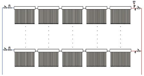
Apricus Solar Hot Water System - Technical Manual

  1. Introduction                                                           transfer fluid in the collector loop. The water drains
                                                                            by gravity back to the storage tank or an auxiliary
                                                                            (header) tank when the circulation pump stops, thus
  1.1 Foreword                                                              preventing overheating and freezing. This system
  Congratulations on taking a major step towards reducing                   provides a high level of protection as it does not rely
  your total home energy usage and making a positive                        on valves or controllers that could fail under adverse
  difference to the environment we live in.                                 freezing conditions. The disadvantage of the system is
                                                                            that it requires a pump with a high static lift to fill the
  Apricus Australia is a provider of premium solar hot water                collector when the system starts up, it is also important
  systems. These systems use high efficiency evacuated                      that all piping is sloped, ensuring that the collector is
  tube collectors to provide free hot water generated purely                at the top and the tank at the bottom. U-bends are
  by the sun’s energy.                                                      strictly not allowed.
                                                                      »»    Expansion control valve (ECV) - Installed on the cold
  1.2 Scope                                                                 mains line to relieve excess pressure.
  This manual has been designed to cater for the needs of             »»    Flow Line - indicates the plumbing line running
  the end-user, installer and service agent.                                from the tank (or heat exchanger) to the inlet of the
  Refer to section ‘8.1 Apricus System Schematics’ for AS/                  collector. This line incorporates the circulation pump.
  NZS2712:2007 approved system designs. Any deviation                 »»    Header - is the copper “heat exchanger” pipes in the
  from these system designs will NOT be eligible for                        solar collector through which the water flows.
  government or state rebates.                                        »»    Heat Pipe: A copper pipe that sits inside the evacuated
                                                                            tube and is inserted into the collector manifold. A
  Customised system designs and larger commercial                           small volume of liquid acts as a heat transfer fluid. It
  systems should be validated and approved by a qualified                   absorbs heat via evaporation, and transfers heat to the
  hydraulic engineer prior to installation in collaboration                 system fluid via condensation.
  with Apricus.                                                       »»    Insolation - solar radiation level, expressed in kWh/
                                                                            m2/day
                                                                      »»    Manifold - Refers to the solar collector which contains
  1.3 Terminology                                                           the header through which potable water flows.
  The terminology used from region to region differs and so
                                                                      »»    Open Loop or Direct Flow: Open loop active systems
  to avoid confusion please note the following terminology.
                                                                            circulate water directly from the tank, through the
  »» AP-30: Standard Size solar thermal collector for
                                                                            collectors. This design is efficient and lowers operating
     commercial projects consisting of 30 Apricus evacuated
                                                                            costs, but is not appropriate if the water supply is
     tubes.
                                                                            hard because calcium deposits quickly build up in the
  »» Bank (of collectors): Two to five Apricus collectors in
                                                                            bottom header of the collector. Open loop systems
     series.
                                                                            have limited freeze protection, usually achieved
  »» Boost - The process where a heating component (such
                                                                            through controller functions; by running the pump
     as an electric element or gas heater) is used to provide
                                                                            and forcing warm water from the tank to the collector,
     additional heating when solar-heated water is not of
                                                                            when the collector temperature approaches zero.
     an adequate temperature.
                                                                      »»    Pressure Limiting Valve (PLV): A valve installed on the
  »» Clean Energy Regulator (CER) - A statutory authority
                                                                            cold water mains line designed to limit system pressure
     established to oversee the implementation of the
                                                                            to a set design pressure. A typical value is 500 kPa.
     Large-scale Renewable Energy Target (LRET) and the
                                                                      »»    Pressure temperature relief valve (PTRV) - installed
     Small-scale Renewable Energy Scheme (SRES).
                                                                            on the hot water storage tank to relieve pressure, and
  »» Closed loop: In a closed loop system the heat transfer
                                                                            excessive temperatures.
     fluid is pumped through the collectors and a heat
                                                                      »»    Return Line - indicates the plumbing line running from
     exchanger is used to transfer heat from the collector
                                                                            the outlet of the collector back to the tank.
     loop to the water in the tank. Closed loop systems are
                                                                      »»    Stratification - the passive separation of water into
     used in areas where freezing conditions are common
                                                                            distinct layers of different temperatures; where the
     and the transfer fluid in the manifold is generally
                                                                            temperature at the top of the tank can be significantly
     glycol or an antifreeze fluid. These systems are
                                                                            higher than the temperature at the bottom.
     more expensive to construct and install, and require
     maintenance.
  »» Collector - The Apricus solar collector is the manifold
     with heat pipes and evacuated tubes inserted.
  »» Drainback: Drainback systems use water as the heat

  Page 4 of 49                  AA8.2.1.7.1-Apricus-Technical-Manual-V2.0                            Copyright © 2014 Apricus Australia Pty Ltd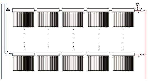
Apricus Solar Hot Water System - Technical Manual

  1.4 Certification                                                     2. Warnings and Precautions
  AS/NZS2712 - The Australian Standard for solar collectors.
  Testing to meet this includes resistance to glass breakage
  and impact resistance under certain conditions including              2.1 Installer Requirements
  hail, stagnation conditions, protection against water                 Installation must be completed by a licensed plumber in
  ingress and structural strength.                                      accordance with the requirements listed below, as well as
                                                                        any relevant local standards and regulations.
  ‘Apricus Australia has obtained AS/NZS 2712:2002 certification
  through Global Mark. The certification number is 100633.’             »» AS/NZS 3500 – National Plumbing and Drainage Code.
                                                                        »» AS/NZS 2712.2007 – Solar and Heat Pump Water
  SRCC - The Solar Rating and Certification Corporation                    Heaters: Design and Construction.
  (SRCC) is a not for profit organization that assesses solar           »» AS/NZS 4234.2008 – Heated Water Systems –
  collectors. This allows solar collectors to be compared to               Calculation of Energy Consumption.
  one another on an independent platform. There is also a               »» AS/NZS 5601.2004 – Gas Installations
  similar program for solar water heating systems.

  ‘Solar Collector – SRCC OG-100 North America                          2.2 Occupational Health and Safety
  Apricus has obtained SRCC OG-100 for the AP-10, 18, 20, 22 &          The installer must adhere to occupational health and
  30 tube evacuated tube solar collectors. Certification numbers:       safety guidelines and other relevant industry associations.
  100-2004003A/B/C/D. Apricus North America has obtained                Under no circumstances should any installer attempt to
  SRCC OG-300 for a full range of systems.’                             install an Apricus solar hot water system without reading
                                                                        and understanding this installation manual. For any
  ITW - Solar Keymark is the most widely recognised                     queries Apricus staff may be contacted on 1300 277 428.
  European standard for solar collectors. The testing done
  through this standard ensures that the collectors are                 2.3 Over Pressure and Temperature Protec-
  reliable in both performance and quality.
                                                                        tion
  ‘Apricus has obtained Solar Keymark certification for its AP-10,
  20, 22 & 30 tube evacuated tube solar collectors.’                    2.3.1 Pressure Temperature Relief
                                                                        Any system design must allow a means of pressure
  AS/NZS3498 - Applies to the hot water system. By                      release at no more than 850kPa, using a PTRV. The PTRV
  meeting this standard, the tank, and the entire system                must have a downward direction copper pipe connected
  meets requirements. Most importantly is the Watermark                 that is open to the atmosphere, running the expelled hot
  certificate meaning that all the products that Apricus                water or air to a safe, frost free and appropriate drainage
  provides in a given system from collector through to valves           location. From time to time the PTRV may discharge small
  will meet Australian standard in relation to potable water.           amounts of water under normal operations, this can be
                                                                        up to 10% of tank capacity. If the tank is installed indoors,
  ‘Apricus Australia has obtained AS/NZS3498 for all the systems        a safe-tray must be installed beneath the hot water tank
  available in the CER register through Global Mark. The                to safely collect any water expelled from the PTRV.
  certification number is 40107.‘
                                                                        2.3.2 Mains Pressure Control
  1.5 Conversions                                                       Where the mains pressure supply can exceed or fluctuate
  •   1kWh = 3600kJ = 860kcal                                           beyond the pressure of 500kPa, a pressure-limiting
  •   1 kcal will heat 1 litre of water by 1°C                          valve must be fitted to the cold mains line. The device is
  •   1 J/s = 1W = 0.860421kcal/hr                                      installed after the isolation valve (duo valve) and should
  •   1kWh/m2/day = 3.6MJ/m2/day                                        have a pressure limit of 500kPa.

                                                                        In some states it is a mandatory requirement that an
                                                                        expansion control valve be fitted on the cold mains line
                                                                        to provide a form of pressure relief. A separate drain line
                                                                        must be run for this relief valve (as per AS/NZS 3500). If
                                                                        unsure please check with the local authority.

  Page 5 of 49                    AA8.2.1.7.1-Apricus-Technical-Manual-V2.0                         Copyright © 2014 Apricus Australia Pty Ltd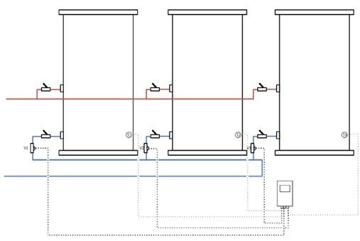
Apricus Solar Hot Water System - Technical Manual

  2.4 Water Quality
  Water quality is an important aspect of system lifetime.                                        WARNING
  For the system to be warranted, the water used in the
                                                                        Freeze protection will not operate if there is no power
  system must meet the requirements outlined in Table 1.
                                                                        supply to the controller or pump.
  Table 1. Water Quality Threshold Values
                                                                       2.6.2 Lightning Protection
   Total Dissolved Solids     < 600 mg/L or ppm
                                                                       At installation locations that are prone to lightning
   Total Hardness             < 200 mg/L or ppm                        strikes, it is advisable to earth/ground the copper
   Electrical Conductivity        850 µS/cm                            circulation loop of the collector to avoid lightning related
   Chloride                   < 250 mg/L or ppm                        damage, or electrical safety issues. Refer also to local
                                                                       building codes regarding lightning safety and grounding.
   pH Level                   Min 6.5 to Max. 8.5
   Magnesium                   < 10 mg/L or ppm                        The inclusion of a residual-current device (RCD) is highly
   Sodium                     < 150 mg/L or ppm                        recommended for these lightning prone areas.

  If in doubt contact your local water authority or have a             2.6.3 Hail Resistance
  water test completed. In areas of poor water quality all             The borosilicate glass evacuated tubes have been tested
  major components will have a reduced life due to the                 under the Australian Standards requirement (AS/NZS
  harshness of the water.                                              2712:2007 – Solar and heat pump water heater – design
                                                                       and construction). The impact resistance test results
  In areas with “hard water” (>200 mg/L or ppm), it is                 indicate that the evacuated tubes are able to withstand
  advised to install a water softening device to ensure the            impact from hailstones up to 25mm/1” in diameter at 25
  long term efficient operation of the system is met. It is            m/s.
  also advisable that a glass-lined tank is used as opposed
  to a stainless steel tank, since the glass-lined tank has a          In the unlikely circumstance that an evacuated tube
  sacrificial anode to protect from corrosion.                         should become broken it can be easily replaced. The
                                                                       solar collector can still function properly with one or
  2.5 Legionella Control                                               more broken tubes, however it will result in a reduced
  Legionella bacteria can be found naturally in the                    heat output from the collector. A broken evacuated tube
  environment and thrives in warm water and damp places.               should be replaced by professional installers or service
  It can weaken the body’s immune system, which can                    agents only.
  increase the chances of developing Legionnaires’ disease.
                                                                       2.7 Stagnation and No-Load Conditions
  To ensure legionella growth is inhibited, the boosting
  regime must meet the guidelines as shown in section                  2.7.1 Information on Stagnation
  3.2.2 Table 3. This is in accordance with ‘AS3498.2009               Stagnation refers to the condition that occurs when the
  Authorisation requirements for plumbing products -                   pump stops running, due to pump failure, power blackout,
  water heater and hot-water storage tanks’                            or as a result of the high tank temperature protection
                                                                       feature built into the controller, which turns the pump off.
  It is therefore, very important that the auxiliary boosting
  system remains on. It will only activate if the temperature          The system is designed to allow stagnation to prevent the
  falls below the temperatures outlined in section 3.2.2               tank from overheating. This means that the collector and
  Table 3.                                                             plumbing in close proximity may reach temperatures of
                                                                       up to 170°C; therefore components that may be exposed
  2.6 Weather Related Issues and Acts of God                           to the high temperatures such as valves, plumbing or
                                                                       insulation, should be suitably rated.
  2.6.1 Freeze Protection
  All Apricus systems have freeze protection built in. This            The system designs listed in the ‘CER’ Register meet
  is provided by the controller which will circulate water             the No-load system requirements detailed in AS/NZS
  through the collector once the temperature falls below               2712:2007. This means that they will not dump large
  4°C. This freeze protection method has passed Frost                  volumes of water from the PTRV and do not require an
  Level 2 protection (down to -15°C) in line with AS/NZS               auto air-vent.
  2712:2007.

  Page 6 of 49                   AA8.2.1.7.1-Apricus-Technical-Manual-V2.0                         Copyright © 2014 Apricus Australia Pty Ltd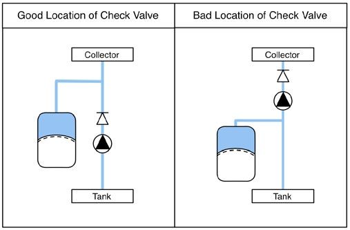
Apricus Solar Hot Water System - Technical Manual

  During periods of extended stagnation, condensation                   2.7.4 Delayed Installation or Use
  pressure shocks can occur in the tank. When the tank is               The manifold and tubes should not be installed and
  topped out and suddenly a hot water load is drawn from                sitting dry (no fluid) for more than 14 days. Prolonged dry
  the tank this can lead to rapid mixing of cold water and              stagnation may void the warranty as it could affect heat
  superheated steam in the return line mixing. This can                 pipes or tube longevity.
  produce a “gurgling” noise, as the steam is hypothesized
  to collapse on itself upon rapidly cooling and condensing.            The manifold MUST NOT be left without tubes and
  This is a normal occurrence in any hot water storage                  installed on the roof for any period of time, particularly
  system and does not affect the system’s operation                     during periods of rainfall or snowfall. There is a high
                                                                        probability of water entering the manifold and causing
  2.7.2 Hydrogen Build Up                                               damage to the glass wool insulation.
  Glass lined (vitreous enamel) tanks are fitted with a
  Magnesium anode to provide corrosion protection for the               If the installation cannot be completed fully and the
  tank from the storage water. Small quantities of hydrogen             system must be left dry for a period longer than 14
  gas can be released by the anode, which generally remains             days, the collector must be covered. The collector can
  dissolved in the water and flushed away as hot water is               be covered with a durable, waterproof cover to prevent
  used from the tank. Depending on the water quality there              water ingress, or access to insects or birds.
  may be a degree of hydrogen build-up in the tank if the
  water heater hasn’t been used for two or more weeks.

  To resolve the build-up of hydrogen within the tank
  “purge” the tank for approximately 30 seconds from the
  lever on the PTRV.

  2.7.3 Water Boiling Temperatures
  The boiling point of water varies based on the pressure
  within the hot water system. Under stagnation and no
  load conditions, the solar collector has the potential
  to reach temperatures well above 100°C. As the water
  temperature rises and water expands this creates pressure
  within the system. As the temperature rises, so too does
  the boiling point of water. This is why the solar hot water
  system (despite being at temperatures in excess of 100°C)
  will not boil and produce steam. Table 2 Illustrates how
  the boiling point increases with pressure.

  Table 2. The Relationship Between Pressure and Boiling Point
        Pressure (kPa)           Boiling point (oC)
             101                        100
             203                        120
             304                        133
             405                        143
             507                        151
             608                        158
             709                        164
             811                        170

  Page 7 of 49                    AA8.2.1.7.1-Apricus-Technical-Manual-V2.0                        Copyright © 2014 Apricus Australia Pty Ltd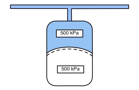
Apricus Solar Hot Water System - Technical Manual

  3. Information for End-User                                        3.2 How Boosting Works
                                                                     3.2.1 Boosting Explained
  3.1 How Solar Heating Works                                        If the solar contribution during the day is not enough
                                                                     to raise the water to a suitable temperature, an electric
  3.1.1 Introduction                                                 or gas booster can provide additional heating. During
  Apricus strongly believe in informing the homeowner                sufficient sunny weather, the solar collector will normally
  about the basic operation of the solar water heating               be able to provide enough hot water, but during winter
  system. By gaining a basic understanding you can develop           months and overcast days boosting may be required.
  realistic expectations about the operation of the system,
  develop habits which maximise energy savings and most              As a regulatory requirement, all solar hot water
  importantly, ensure safe and reliable operation.                   installations must include a tempering valve which mixes
                                                                     the hot water coming out of the storage tank with cold
  3.1.2 Summer and Winter Solar Heating                              water to limit the temperature to 50°C.
  Solar radiation is only half or one third as strong in the
  winter months compared to summer, and therefore                    3.2.2 Legionella Bacteria - Importance of Boosting
  not able to provide the same amount of hot water as in             It is a legal requirement that water be heated on a
  summer. For optimal performance of the solar system it             regular basis to kill Legionella bacteria that can lead to
  is recommended that the collectors be angled (pitched)             Legionnaires disease. The frequency this temperature
  at no less than 20 degrees. For increased performance              must be reached varies, and is explained in Table 3:
  during winter it is recommended that collectors are
  pitched at latitude plus 10-20 degrees, Correct tilting of         Table 3. Minimum Heat Requirements
  the system will provide increased year round performance            Type of Apricus System        Minimum heat
  and reduce energy costs further.                                    Installed                     requirements
                                                                      Bottom element electric       Once per week to 60°C for 32
  3.1.3 How the Apricus System Works                                  boosted system                minutes
  The Apricus solar collector converts the sun’s energy into
                                                                      Mid element electric boosted
  heat, quite different to photovoltaic (PV) solar panels,                                         Once per day to 60°C
                                                                      system
  which convert the sun’s energy into electricity.
                                                                                                    Minimum 70°C each time
                                                                      Gas boosted systems
                                                                                                    water is used
  How the Apricus system works:
  1. The evacuated tubes absorb the sun’s energy and
     convert it to usable heat.                                      3.2.3 Electric Boosted Systems
  2. The heat inside the evacuated tube, is carried via              If the system is electric boosted, when the electric element
     copper heat pipes to the insulated manifold, this               is activated it will heat up all the water above the element
     contains a copper heat exchanger.                               to 60°C (or the thermostat setting). This heating can take
  3. An electronic controller measures the temperature of            as long as 3-4 hours if the tank is cold.
     water in the manifold and compares it to the water              Note: Apricus recommends that the electric booster is left
     in the bottom of the storage tank. If the manifold              on, or controlled by a suitable timer.
     temperature is higher, the controller switches on a
     circulation pump which brings the solar heated water            3.2.4 Gas Boosted Systems
     back down to the storage tank.                                  Depending on the gas booster used, the start-up
  4. Throughout the day, the controller switches the pump            temperatures vary. For an Apricus gas booster, if the
     on and off to continuously heat water in the storage            incoming water temperature is less than 55°C, the booster
     tank.                                                           will activate and heat water to 70°C. If the incoming water
  5. When the maximum temperature in the tank is                     is greater than 55°C the booster will not start and water
     reached (85°C), the pump is turned off and no more              will flow directly to the outlets.
     water is circulated until the temperature drops below
     this value.                                                     Non Apricus boosters are typically configured to heat any
                                                                     water below 70°C to 70°C. Refer to the individual booster
                                                                     manual for more detailed information on these settings.

  Page 8 of 49                 AA8.2.1.7.1-Apricus-Technical-Manual-V2.0                         Copyright © 2014 Apricus Australia Pty Ltd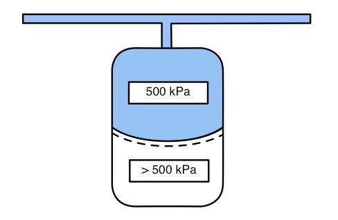
Apricus Solar Hot Water System - Technical Manual

  3.3 System Maintenance & Precautions
  3.3.1 System Maintenance
  •   Cleaning - The Apricus tubes do not usually need
      cleaning, regular rain and wind should keep the tubes
      clean.
  •   Pressure & Temperature Relief Valve (PTRV) - The
      PTRV is located near the top of the hot water storage
      tank. It is designed to release pressure in the tank as
      water expands and contracts during normal heating.

      The lever on the PTRV should be carefully lifted for a few
      seconds then placed down, once every 6 months. This
      will help prevent any debris or scale build up in the valve.

                            WARNING
   When the PTRV is lifted hot water will be discharged.
   Ensure the drain pipe from PTRV is clear.

  •   Visual Check - Apricus recommend periodic visual
      checks of your system:
  a. Check for leaks around the storage tank and pipe work
  b. Ensure the pump station is dry and free from moisture
  c. If the tubes are safely visible from ground
     height, ensure all tubes are still dark in colour.
     (Note: if the tubes are a milky/white colour
     the vacuum has escaped and the tube will
     not be working as efficiently as it should be)

                          WARNING
   Pipe work can be extremely hot, do not touch any
   exposed copper piping.

  3.3.2 Glass Lined Tank Precautions
  Glass lined (Vitreous enamel) tanks are fitted with a
  magnesium anode to provide corrosion protection for
  the tank from the stored water. Apricus recommend the
  anode be inspected at least every three (3) years, and
  serviced as required.

  Small quantities of hydrogen gas can be released by the
  anode which generally remains dissolved in the water.
  This is then flushed away during normal use.

  Depending on the water quality there may be a degree of
  hydrogen build up in the tank if the water heater hasn’t
  been used for two or more weeks. To resolve the build-
  up of hydrogen within the tank “purge” the tank for
  approximately 30 seconds from the lever on the PTRV.

  Page 9 of 49                    AA8.2.1.7.1-Apricus-Technical-Manual-V2.0   Copyright © 2014 Apricus Australia Pty Ltd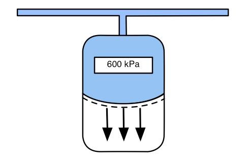
Apricus Solar Hot Water System - Technical Manual

  3.4 End-User Troubleshooting Guide
  Table 4. Basic Troubleshooting Guide
   Problem                         Cause                          Solution
                                   Air lock in manifold           Contact Apricus Australia
   Pump Continuously Running
                                   Insufficient flow rate         Increase pump speed
                                Maximum temperature This is normal operation, controller switches pump off once
   Pump is not circulating even reached in the tank   maximum temperature is reached to prevent over-heating.
   during sunny weather
                                Possible sensor issue Contact Apricus Australia
                              Freeze          protection This is normal, but if the pump is running more than once an hour,
   Why is the pump running at operating                  additional insulation on the collector line should be installed.
   night?                     Possible faulty non-return
                                                         Contact Apricus Australia
                              valve
   Why is the controller L.E.D.
                                Possible sensor issue             Contact Apricus Australia
   light flashing red?
                                                              Ensure gas booster is operational.
                                   Electric or gas booster is
                                                              Electric booster should have the thermostat temperature set to at
                                   not configured correctly
                                                              least 60°C. Booster must be left on off-peak, or controlled by timer.
   Why is the water not hot Household hot                 water Contact Apricus Australia for advice. Remember an efficient shower
   enough?                  usage too high                      head uses 9 litres/minute. (10 minute shower = 90ltrs water)
                                                                  A tempering valve must be installed on every solar hot water
                                   Tempering valve installed      system. Tempering valves will mix water down to 50°C
                                                                  Tempering valve may need replacing or servicing.

  Page 10 of 49                   AA8.2.1.7.1-Apricus-Technical-Manual-V2.0                        Copyright © 2014 Apricus Australia Pty Ltd
Apricus Solar Hot Water System - Technical Manual
4. Pre-Installation 4.2 Site Inspection
4.2.1 Collector Location
4.1 System Selection The location of the solar collector is crucial to achieving
Proper system selection is crucial to ensure that all the optimal system performance. A number of factors need
hot water needs for the home are being met. The system to be considered when determining the placement of the
should be designed to meet 90-100% of the household collectors on the roof of a building. These are detailed
needs in summer and 50-60% in winter. below:
A number of considerations need to be made including: • Solar collector vicinity to tank: The collector should be
the number of residents in the house, the time of day positioned as close as possible to the storage tank to
when most hot water will be used, the location of the avoid long pipe runs and minimise heat loss.
customer within Australia and the resources available on • Collector Orientation with respect to the sun: To
site. ensure optimal heat output the collector should face
the equator, which in Australia and New Zealand
Apricus Australia has designed its systems to meet the (Southern hemisphere) is due North. A deviation of
optimal demand required in most residential homes for up to 15° east or west off due north is acceptable, and
domestic hot water requirements. Figures 1 & 2. Show will have minimal affect on heat output.
a sizing guide which can be used as a “Rule of Thumb” • Collector Plane: Both sides of the manifold can be used
for choosing a system that best meets the needs of the interchangeably as the inlet and outlet ports. However,
household. if the manifold is not level horizontally, the higher side
must be used as the outlet since hot water rises.
Warm Regions Cold Regions • Collector Angle: So that the collector achieves
STC Zone 1 & 2 STC Zone 3 & 4 maximum solar exposure, collectors are to be installed
Warm Regions Cold Regions at an angle of the location’s latitude +/- 10°. E.g. Sydney
STC Zone 1 & 2 STC Zone 3 & 4 is at 34° S latitude, therefore the optimal angle for
the collector on the roof would be 24-44° S. In some
installations it may desirable to achieve an install angle
of +10° latitude as this will optimise winter output
since the sun is lower in the sky during Winter. This
can also reduce stagnation effects in summer from
over sizing.
• Shading: Collectors should be located so that shading
does not occur for at least 3 hours either side of 12pm
Figure 1. Collector sizing guide noon local time. Partial shading due to small objects
160 litres up to such as antennas and small flues are not of great
concern.
160 litres up to
250 litres up to
4.2.2 Mounting Frame Location
Prior to installation of the mounting frame it is
250 litres up to essential to carry out a site inspection and ensure
that the site is compliant with the conditions
315 litres up to stipulated in section ‘8.2 - Conditional Requirements’.
In the case where conditional requirements are not met,
315 litres up to a certified structural engineer may also be consulted
prior to install to provide professional design work that
400 litres up to will allow for the site to accommodate Apricus certified
mounting frame systems.
400 litres up to
Figure 2. Tank sizing guide
Page 11 of 49 AA8.2.1.7.1-Apricus-Technical-Manual-V2.0 Copyright © 2014 Apricus Australia Pty LtdApricus Solar Hot Water System - Technical Manual
4.2.3 Storage Tank Location • Do not remove and/or expose the tubes to sunlight
• The storage tank should be located as close as possible until ready to install, otherwise the heat pipe tip will
to the most frequent draw off points in the building become very hot, sufficient to cause serious skin burns.
such as the bathroom or kitchen. If the storage tank is Note: The outer glass surface will not become hot.
located a long way from hot water draw points a hot
water circulation loop on a timer may be considered to WARNING
reduce the time-lag for water to heat up and resultant
water wastage. NEVER touch the inside of the evacuated tube or heat
• The tank should not obstruct any windows, doors pipe tip after exposure to sunlight.
or exits and should cause minimal intrusion to the WEAR thick leather gloves if handling the heat pipe.
existing site. WEAR safety glasses at ALL times when handling the
• For glass-lined tanks, consider the requirement of glass tubes.
anode removal and replacement maintenance.
4.4.2 Pump Station Inspection
Every domestic solar hot water system supplied by Apricus
4.3 Transport and Unpacking comes with an Apricus Pump Station Kit. The Apricus Pump
Station Kit comes bundled with the essential components
4.3.1 Transport of Components required for installation of a solar hot water system. The
• When transporting boxes, note the orientation of the kit comes pre-packaged and can easily be connected to
“THIS WAY UP” arrows. plumbing.
• Ensure all boxes are strapped and secured to prevent
movement during transit. Pump station components include:
• All tanks must be transported upright. Stacking is not • Check valve
recommended for any tanks. • Pump unions
• Products should always be handled with care. Damage • Flow meter
occurred during the transportation is not covered • Tempering valve (solar rated)
under product warranty. • Circulation pump
• Controller
4.3.2 Unpacking of Components • Pump station lid & base
• When unpacking, take care to ensure that the
components are not damaged in the process.
4.4.3 Mounting Frame System
• Avoid using sharp blades or knives as this can scratch
Ensure that all necessary components required for
the surfaces of the products particularly the evacuated
installation have been received in the packaging. Figure 3
tubes and tanks.
& 4 are diagrammatic guides showing what is included in
• For evacuated tubes and heat pipes, tear open both
a typical mounting frame system. Refer to 8.2.2. Appendix
ends of the box(es) to allow inspection of the vacuum
Table 11, 12a & 12b for number of frame components
at the bottom and for the heat pipes to be exposed for
required.
the application of heat transfer paste.
4.4 Component Inspection
4.4.1 Evacuated Tubes & Heat Pipes
• Ensure that the evacuated tubes are all intact, the
bottom of each tube should be silver. If a tube has
a white or clear bottom, it has lost its vacuum and
should be replaced. In this case, the heat pipe should
be removed and inserted into the replacement tube.
• The evacuated tubes have rubber tube caps on the
end, these are to protect the bottom tip of the glass
tube from being broken.
• Heat pipes are bright and shiny when newly
manufactured, but will dull and may form dark-grey
surface discoloration over time. This is due to mild
surface oxidation (when exposed to air) and does not
affect the heat pipe’s operation.
Page 12 of 49 AA8.2.1.7.1-Apricus-Technical-Manual-V2.0 Copyright © 2014 Apricus Australia Pty LtdApricus Solar Hot Water System - Technical Manual
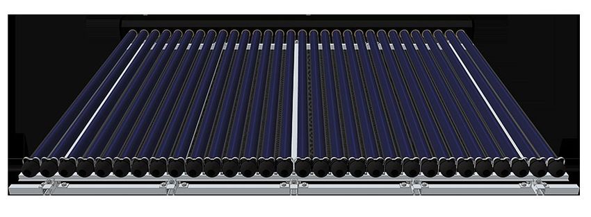
Apricus Flush Mount
This diagram shows our standard AP-30 flush mounted frame suitable for use in all wind regions with: 5 x Tracks and 5
x L-Bracket packs.
4 2
3
1
1 Bottom Track
2 Track
3 Roof Rail
4 L-Bracket Pack
Figure 3. Flush-Mount Frame at 1800 mm spacing with 5 tracks.
Page 13 of 49 AA8.2.1.7.1-Apricus-Technical-Manual-V2.0 Copyright © 2014 Apricus Australia Pty LtdApricus Solar Hot Water System - Technical Manual
Apricus Tilt Mount
This diagram shows a typical cyclonic wind region C frame with: 5 x Tracks, 5 x L-Bracket packs and 5 x Rear Legs. Most
regions across Australia only require 3 x Rear Legs.
5 6
2
1
4
3
1 Bottom Track
2 Track
3 Roof Rail
4 L-Bracket Pack
5 X-Brace pack
6 Rear Leg
Figure 4. Tilt-Mount Frame at 1800 mm spacing with 5 tracks.
Page 14 of 49 AA8.2.1.7.1-Apricus-Technical-Manual-V2.0 Copyright © 2014 Apricus Australia Pty LtdApricus Solar Hot Water System - Technical Manual
5. Installation
5.1 Mounting Frame System
Apricus Australia’s solar evacuated tube mounting frame
systems are made of high-grade extruded anodized
aluminium frame 6005-T5.
There are four easy to install mounting options: flush Figure 5. Flush mount 1500mm Figure 6. Flush mount 1800mm
mounted with roof rail, flush mounted with roof straps,
low angle tilt 30 degrees and high angle tilt 45 degrees.
Our frames are suitable to use in wind regions A, B, C
and D, however these are subject to a set of conditional
requirements. Under this set of conditional requirements
(see section 8.2 Conditional Requirements) these systems Figure 7. Tilt mount 1500mm or 1800mm
are certified to Australian Standard AS/NZS 1170.2:2011
Structural Design Actions Part 2: Wind Actions. See 3. Slide the bottom track into the bottom attachment
section 8.3 Mounting Frame Certification. plates and finger tighten all nuts and bolts.
At time of publication, Apricus has applied for Northern
Territory Deemed to Comply status. We have done
extensive physical load testing for this purpose and have
already obtained a Section 40 - Certificate of Compliance
for our flush-mounted frames. See section 8.4 Section 40
- Certificate of Compliance.
Check with local building authority to confirm whether or Figure 8. Bottom track and attachment plates
not this standard is a regulatory requirement.
5.1.1 Installation Notes FLUSH MOUNT ONLY
The installer is to provide the fixings for the frame to the 4. For flush-mount frames attach the second roof rail.
roof, ensure the fixings are applied in accordance with Continue onto Step 8.
section 8.2 Conditional Requirements and section 5.1.3
Installation – Roof Fixing Guide. Holes can be easily drilled
into the extruded aluminium components. They are to be
no larger than ø10 mm and not closer than 30mm centre
to centre. Tighten frame bolts with spanners or short
shafted socket wrenches only. DO NOT use power tools
or long shafted tools that may over-torque the bolts (as
stainless steel bolts are susceptible to galling/locking).
Bolt assemblies come with spring washers to maintain
long-term tension. Figure 9. Flush mount 1500mm
5.1.2 Installation – Assembly Guide
Apricus Australia’s mounting frame systems come pre-
packaged to ensure the most streamlined and simple
assembly process. Use the following steps as a guide to
assembly.
1. Lay the first roof rail down horizontally (add L-brackets
if using a 5 track system).
2. Attach all tracks to the L-brackets, finger tighten all Figure 10. Flush mount 1800mm
nuts and bolts. Ensure that the track is placed in the
right location based on batten/purlin spacing.
Page 15 of 49 AA8.2.1.7.1-Apricus-Technical-Manual-V2.0 Copyright © 2014 Apricus Australia Pty LtdApricus Solar Hot Water System - Technical Manual
TILT MOUNT ONLY 5.1.3 Installation - Roof Fixing Guide
5. For tilt-mount frames, lay down the second bottom To proceed with attaching the mounting frame to the
track, but attach the L-brackets to the rear legs. Finger- roof, follow all fixing rules as per section 8.2.2 Installation
tighten nuts and bolts. Conditions (for certification to apply). All fixings should
be made equidistant from the front track and rear
leg. This will ensure that the wind loads are equally
distributed across the roof rail. Line up the roof rails with
battens accordingly. For tilt-mount systems the batten/
purlin spacing can be increased where the angle of the
tilt decreases.
Figure 11. Rear leg connection
1800.0mm
6. Attach X-braces to the rear legs. 900.0mm
900.0mm
Figure 16. Roof fixing locations 1800mm
Ensure all roof penetrations are water tight. Use the
Figure 12. X-brace connection following examples as a guide for installation for different
roof types:
7. Attach tri-attachment plates to the track
5.1.4 Tin Roof Installation Example:
For corrugated/tin roofs, place fixings on the peak of the
roofing sheet material to minimize risk of leaks. Fixings
are to be screwed into the batten with minimum 35mm
embedment (for more details see section 8.2.2 Installation
Conditions).
Figure 13. Tilt mount 1500mm Figure 14. Tilt mount 1800mm
35mm 35mm
Figure 17. 35mm embedment into the batten/purlin [rear view]
8. Slide the manifold into the top attachment plates
5.1.5 Tiled Roof Installation Example:
For tiled roofs (where drilling is undesirable) use Apricus
roof straps to attach the frame to the battens/purlins.
Note: systems installed on tiled roofs are not certified
under AS/NZS 1170.2. Roof straps can also be attached to
roof rails by drilling through them.
Figure 15. Manifold connection to frame
9. Using a spanner, tighten all nuts and bolts used for
attachment.
Figure 18. Roof attachment strap example
Page 16 of 49 AA8.2.1.7.1-Apricus-Technical-Manual-V2.0 Copyright © 2014 Apricus Australia Pty LtdApricus Solar Hot Water System - Technical Manual
5.1.6 Adjusting Tilt Mount Angle: 5.3.2 Flow Meter Settings
When installing tilt-mount systems, the mounting frame AS 4234.2008 Heated Water Systems – Calculation of
can be modified to achieve a reduced tilt angle. This energy consumption, Clause 3.7.2 – Low Flow Criteria
would be preferable where the optimum tilt angle is not stipulates that the maximum flow rate is 0.75 L/min/m2
achievable for the given roof pitch and tilt leg. of collector aperture area. Table 5 shows the maximum
flow rate settings for the various Apricus collectors.
To reduce the installation angle of the collectors, the
aluminium legs should be cut to a desired reduced length Table 5. Maximum flow rate requirements
and a new hole should be drilled to allow for securing. By Collector Size Maximum Flow Rate (L/min)
reducing the length of the aluminium tilt leg, the frame 10 Tubes 0.7
is brought closer to the roof and the tilt angle is reduced.
20 Tubes 1
Note that decreasing the tilt angle will consequently 22 Tubes 1.5
decrease the wind loading on the system and as such will 30 Tubes 2
not impact the structural integrity of the system. 40 Tubes 2.5
44 Tubes 2.5
5.2 Collector Manifold Connection Note: Each tube is 0.094 m2 of aperture area
5.2.1 Silver Soldering/Brazing 5.4 Solar Differential Controller
Soldering may be used to connect piping to the collector
header pipe. Only use potable water grade brazing 5.4.1 Controller Settings
material. Care should be taken to avoid overheating the The Apricus controller comes with temperature sensors
copper pipe and exposing the manifold casing to an open and power leads already connected. For most installations
flame. there is no need to alter any of the settings.
The controller has 3 sensor cables. The longest cable is for
5.2.2 Compression Fittings the roof sensor for the solar collector.
Apricus collectors come supplied with 20mm flare x
12mm Male Iron (MI) 90° Elbows. The controller comes pre-set with suitable settings for
most domestic applications:
5.2.3 Press Tools • Pump On = 8°C (Temperature differential between
Seek manufacturers advice before using all press tools. tank and roof sensors)
Press tools are not suitable for direct manifold connection, • Pump Off = 1°C (Temperature differential between
or connecting multiple collectors together. tank and roof sensors)
• Top out = 85°C (Maximum tank temperature)
5.3 Pump Station • Frost Protection = 4°C (temperature for when pump is
forced to cycle)
5.3.1 Installation Guide
Use the following steps as a guideline for the installation The controller provides a digital display providing the 3
of the pump station and connection to piping: sensor temperatures and also signs when faults occur
1. Remove the contents from the box. within the controller readings. To cycle through the
2. Remove the Pump Station Cover from the base plate. temperature display readings press the NEXT button, the
3. Position base plate on the wall making sure there is a current displayed sensor is indicated on the display board
clearance height of 1 to 1.5 metres on the vertical wall, through a flashing icon. Refer to controller manual for
either side of the pump. detailed information.
4. With a spirit level and pen mark screw holes on the
wall for base plate.
5. Drill holes for green plugs.
6. Insert Green plugs into the drilled holes.
7. Fix base plate to wall with the 4 screws and rubber
isolators.
8. Plumb in flow lines to the circulation pump (with a
flow meter and check valve above the pump).
Page 17 of 49 AA8.2.1.7.1-Apricus-Technical-Manual-V2.0 Copyright © 2014 Apricus Australia Pty LtdApricus Solar Hot Water System - Technical Manual
5.4.2 Temperature Sensors 5.7 Evacuated Tubes and Heat Pipes
Apricus solar rated tanks come with two temperature The Apricus evacuated tube solar collector is a simple
sensor ports. The bottom port connects to the Sensor 2 “plug and play” system. See section 4.3.2 Unpacking of
(S2), the middle port connects to the Sensor 3 (S3) sensor. Components for details regarding the unpacking of the
evacuated tubes. Use the following section as a guide to
The third temperature sensor port is located on both installing evacuated tubes.
sides of the manifold. Sensor 1 (S1) must be connected to
the outlet (the higher side). 5.7.1 Installation Notes
• The powder content of the heat paste may have settled
Use a thin layer of thermal paste when inserting all sensors. during freight and storage. To ensure optimal thermal
Ensure insulation covers the opening of the collector conductivity of the paste, place the heat paste tube in
sensor port to prevent water ingress. High temperature a glass of warm water for several minutes.
outdoor silicon sealant can be used to prevent water • If weather conditions are dusty, take care to ensure
ingress to the manifold sensor port. heat paste is not contaminated with impurities, as this
may reduce thermal conductivity and efficiency of the
It is highly recommended that conduit be used to heat paste.
encapsulate the roof sensor and act as another protective • If weather conditions are wet, take care to ensure
layer as it is prone to physical damage by local fauna and water does not enter the inside of the evacuated tube.
extreme weather conditions. The sensor cable should
run along the outside of the insulation and secured every 5.7.2 Installation Guide
20cm with UV resistant nylon cable ties. 1. Open the evacuated tube box on the side with the
heat pipes.
5.5 Insulation 2. Pull the heat pipe out ~10cm and ensure to keep the
• All insulation needs to be solar-rated. Any insulation rest of the tube shaded.
exposed to sunlight must be UV stabilised. 3. Coat each heat pipe bulb with heat transfer paste, this
• Insulate all pipe running to and from the manifold with can be applied using a piece of foam insulation.
insulation of at least 15mm thickness, or 25mm in cold 4. Take out the evacuated tube and turn it upside-down
climates. (heat pipe down) before turning it back upright (heat
• Ensure the insulation is tight against the manifold pipe up). Repeat this several times to disperse the
casing, thus minimising loss of heat from the inlet and copper powder within the heat pipes.
outlet. 5. Guide the heat pipe into the inside of the header port.
• All internal piping as well as external should be Push the heat pipe in full depth.
insulated. This includes at least 1m from the hot 6. Use a damp cloth, to lubricate the outer surface of the
water outlet of the tank, as this copper pipe can be a evacuated tube and the rubber ring in the manifold to
significant point of passive heat losses. minimize friction during insertion.
7. Insert the evacuated tube using a slight twist and
pushing action.
5.6 System Filling and Air Purge 8. Repeat steps 3-7 for the remainder of the tubes.
After all the plumbing connections to the solar collector
9. Using provided tube clips, secure the evacuated tubes
have been made, the solar hot water system needs to
into the bottom track.
be filled with water and the collector loop purged of air.
10.Wipe down each evacuated tube with a damp cloth to
This should be completed prior to insertion of evacuated
ensure a polished and clean installation.
tubes and connection of the tank to the hot water load.
To fill the system:
1. Open the cold mains line and fill up the tank.
2. Turn the pump dial to speed 3 and connect it directly
to the electricity mains rather than the controller.
3. Open up a drain on the solar return line.
4. Where an air-relief valve has been installed, air will be
automatically released from the collector loop. This
should be shut once the line is filled.
5. Filling is completed once there is a constant stream of
water exiting from the solar return line drain.
6. Reconnect the pump to the controller.
Page 18 of 49 AA8.2.1.7.1-Apricus-Technical-Manual-V2.0 Copyright © 2014 Apricus Australia Pty LtdApricus Solar Hot Water System - Technical Manual
5.8 Auxiliary Boosting Components 6. Post Installation
5.8.1 Electric Booster, Thermostat and Element Set-
up 6.1 Commissioning
To ensure optimal operation and to maintain the integrity
of Apricus solar hot water systems, commissioning is
WARNING an essential process. Ensure that each of the following
WARNING: All electrical connections must be completed processes is carried out prior to leaving the site.
by a qualified electrician.
6.1.1 System Operation Check
• The thermostat should be set to 60°C or above as per Given good sunlight, the evacuated tubes will begin to
AS/NZS 3498. produce heat after a 5-10 minute “warm up” period. There
• To adjust the temperature setting: should be an observable increase in the temperature
»» Disconnect the electrical power supply to the tank reading at the roof sensor on the controller.
»» Remove the element cover When there is an 8°C temperature differential between
»» Using a screw driver, rotate the thermostat dial to ROOF and TANK sensors the circulation pump should turn
the desired temperature. on.
• Where off-peak periods are unavailable it is advisable
that a timer be installed to heat the system up to 60°C After initial completed installation of collector, watch the
at least: i) once per week (bottom element tanks), or; operation of the pump and controller for at least 5 ON/
ii) once per day (middle element tanks) to prevent OFF cycles or 15 minutes as the system stabilises. This
legionella formation. See section 2.5 Legionella process may take longer on overcast or cold conditions.
Control.
6.1.2 Photo Records
5.8.2 Gas Booster Setup Take several photos of the installed product including:
• All gas boosters come pre-set to heat up to 70°C as per plumbing lines to/from the tank and collector and sensor
AS/NZS 3500, see section 2.5 Legionella Control for port connections. These will serve as an important record
more information. for future servicing or warranty issues.
• Installations must be compliant with AS/NZS 5601.
• Larger gas systems require adequate flueing and 6.1.3 Installation Record Form
ventilation, this should also be done in accordance Complete the installation record form that is supplied, This
with AS/NZS 5601. will ensure that the customer is registered on the Apricus
• To customize settings please refer to relevant database and increase the speed with which warranty and
manufacturer’s installation manual. service issues can be dealt with. The installation record
forms can be returned via:
a) Fax a copy to: 02 9475 0092;
b) E-mail a copy to: warranty@apricus.com.au;
c) Mail a copy to: Apricus Warranty, PO Box 6109,
Silverwater, NSW, 1811; OR,
d) Installation/record forms can also be submitted
electronically online at: http://www.apricus.com.au/
6.1.4 Rebate Forms
Complete any applicable rebate forms that require an
installers signature prior to leaving the site.
6.2 Maintenance
Under normal conditions the solar collector is maintenance
free. Please refer to the documentation provided by the
manufacturer of other components for maintenance
guidelines.
Maintenance and servicing should only be completed by
a certified plumber, with experience in solar hot water
systems.
Page 19 of 49 AA8.2.1.7.1-Apricus-Technical-Manual-V2.0 Copyright © 2014 Apricus Australia Pty LtdYou can also read