User's Information Manual Series 100 - Models: AHPA-25 - AHPA- 60 - AHPA-90 - AHPA-125 - AHPA-185 - AHPA-250 - A.O. Smith
←
→
Page content transcription
If your browser does not render page correctly, please read the page content below
User’s Information
                              Manual
                            Series 100
                         Models: AHPA-25 - AHPA-
                         60 - AHPA-90 - AHPA-125 -
                           AHPA-185 - AHPA-250

                           Air Source Heat Pump
                          Commercial Heat Pump
                          Water Heating Systems
      Certified
    UL 1995:2015
CSA C22.2 NO. 236:2015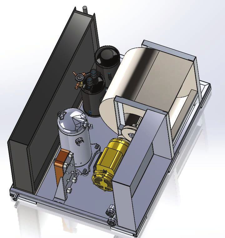
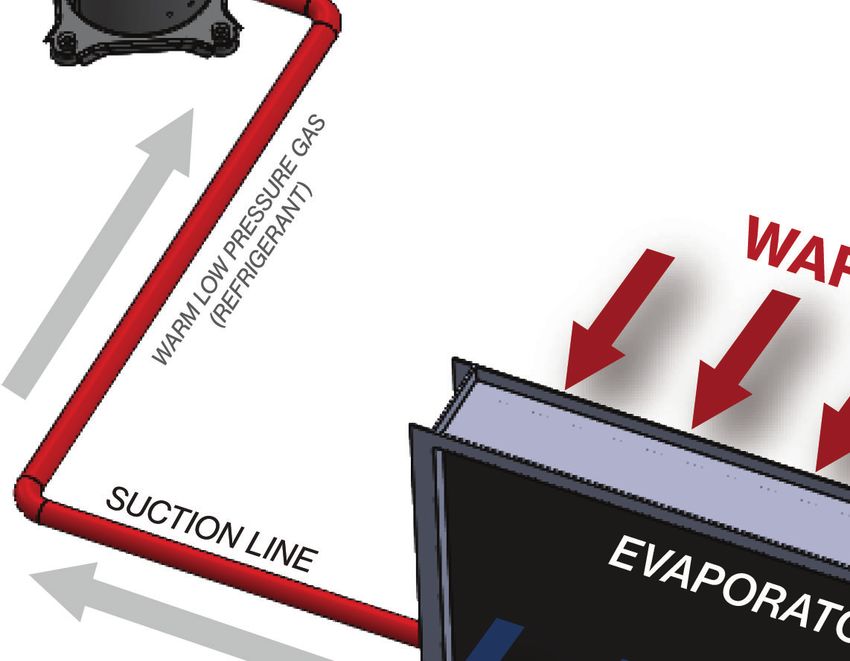
TABLE OF CONTENTS
SAFE INSTALLATION, USE AND SERVICE..................1                                      TEMPERATURE-PRESSURE RELIEF VALVE.....................12
GENERAL SAFETY INFORMATION........................... 2                                    TANK SELECTION...............................................................12
  PRECAUTIONS......................................................................2         SOLAR TANKS.................................................................12
  GROUNDING INSTRUCTIONS............................................2                      CONTAMINATED AIR.........................................................13
INTRODUCTION........................................................3                      STORAGE & HANDLING...................................................13
  QUALIFICATIONS.................................................................3           STORAGE RECOMMENDATIONS..............................13
  PREPARING FOR THE INSTALLATION................................3                        INSTALLATION........................................................14
  PRINCIPLE OF OPERATION..................................................4                REQUIRED ABILITY.............................................................14
  THE REFRIGERATION CYCLE..............................................4                   GENERAL.........................................................................14
  AIR TEMPERATURE RANGE.................................................4                  REQUIRED TOOLS & MATERIALS...................................14
  WATER TEMPERATURE RANGE..........................................4                         INSTALLATION & START UP TOOLS........................14
  REFRIGERANT CHARGE........................................................4                SERVICE TOOLS..............................................................14
  EQUIPMENT DISPOSAL........................................................4              UNIT PLACEMENT..............................................................14
FEATURES & COMPONENTS......................................5                                 CEILING SUSPENSION...................................................14
  PRODUCT ILLUSTRATION...................................................5                   PAD MOUNTING.............................................................15
  AIR TO WATER CYCLE............................................................6          ELECTRICAL CONNECTIONS............................................15
  ROUGH IN DIMENSIONS.....................................................7                  CORRECT VOLTAGE AND PHASE.............................15
  PERFORMANCE SPECIFICATIONS....................................7                            BRANCH CIRCUIT DISCONNECT SWITCH.............15
INSTALLATION REQUIREMENTS...............................8                                    TRANSFORMER CONFIGURATION............................15
  WATER TEMPERATURE........................................................8               WATER CONNECTIONS......................................................15
    MAXIMUM SYSTEM TEMPERATURE...........................8                                   INSTALLATION INSTRUCTIONS.................................15
    INLET & OUTLET WATER TEMPERATURE..................8                                    SINGLE TANK CONFIGURATION.....................................16
  AIR TEMPERATURE...............................................................8          MULTIPLE TANK CONFIGURATION.................................16
    ENTERING AIR TEMPERATURE......................................8                        CONDENSATE DRAIN LINE.............................................16
  LOCATING THE WATER HEATER...........................................8                    STANDARD TANK THERMOSTAT....................................16
    INDOOR/OUTDOOR INSTALLATION...........................8                                TEMPERATURE SENSOR INSTALLATION......................17
    FREEZING TEMPERATURES............................................8                     AIR FLOW AND DUCTING...............................................17
    COASTAL REGIONS...........................................................8              GENERAL GUIDELINES.................................................17
    HEAT SOURCE....................................................................8         DUCT SIZING...................................................................17
    CONDITIONED SPACE.....................................................9                  DUCT INSULATION........................................................17
    UNCONDITIONED SPACE...............................................9                      MAKE DUCT CONNECTIONS....................................17
  CLEARANCES.........................................................................9       BUILDING AIR PRESSURE............................................17
  ELECTRICAL REQUIREMENTS............................................9                       NEGATIVE PRESSURE....................................................17
    MINIMUM CIRCUIT AMPACITY & MAXIMUM FUSE                                                  POSITIVE PRESSURE......................................................17
    SIZE.........................................................................9           WHEN TO INSTALL DUCTING.....................................18
    MINIMUM WIRE SIZE....................................................10                  SUPPLY AIR DUCTING.................................................18
  WATER PIPING.....................................................................11        DUCT SIZING CHART...................................................18
    MINIMUM PIPE SIZE.......................................................11               RETURN AIR DUCTING.................................................19
    PIPE SUPPORT.................................................................11        BLOWER ASSEMBLY ADJUSTMENTS..............................19
    PIPE INSTALLATION........................................................11          INSTALLATION CHECKLIST......................................19
    COLD WATER SUPPLY.....................................................11                 LOCATION.................................................................19
  WATER PRESSURE...............................................................11            AIR FLOW & DUCTING....................................................19
  CLOSED WATER SYSTEMS................................................11                     WATER PIPING................................................................19
  THERMAL EXPANSION......................................................11                  CONDENSATE DRAIN.....................................................20
  MIXING VALVES..................................................................11          ELECTRICAL.............................................................20
  CONDENSATE REMOVAL.................................................12                    PRE-STARTUP CHECKLIST..................................................20
  CONTAMINATED WATER...................................................12                  3 PHASE STARTUP PROCEDURES......................................20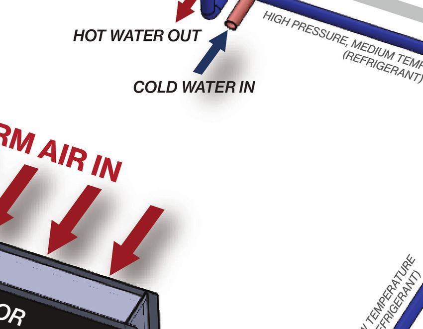
TABLE OF CONTENTS
  SINGLE PHASE STARTUP PROCEDURES..........................21                              HOME SCREEN....................................................................29
  INITIAL START-UP.................................................................22      ALARM SCREEN..................................................................29
  MASTER CONTROL PANEL                                                                     CONFIGURATION SCREEN...............................................29
  PRE-STARTUP CHECKLIST ................................................22               STOP SCREEN..........................................................30
  ROTATION DIRECTION......................................................22             IP CONFIGURATION................................................30
  STARTING SOUND..............................................................22         MAINTENANCE AND SERVICE................................30
START UP.................................................................22                ROUTINE MAINTENANCE.................................................30
SETTING LOWER LIMIT CONTROL                                                                AIR FILTERS..........................................................................30
VALVE LIMIT FOR SINGLE-PASS.............................23                                 DRAIN PAN..........................................................................30
  PURGING THE CONDENSER ON A PLC..............................24                           BLOWER ASSEMBLY...........................................................30
ELECTRONIC TEMPERATURE CONTROLS..............24                                            BLOWER MOTOR................................................................31
  CONTROLLER..........................................................24                   EVAPORATOR COIL............................................................31
  FUNCTION RANGES & SETTINGS...................................24                          CLEANING INTERNAL INSULATION................................31
    PARAMETER SETTINGS................................................24                   CHECKING REFRIGERANT CHARGE...............................31
  SCREEN NAVIGATION........................................................24              CHECK AIR FLOW..............................................................31
  BASIC MODE........................................................................25     CHECK WATER TEMPERATURE RISE...............................31
  ADVANCED MODE............................................................25              FACTORY CHARGE.............................................................32
  RESTRICTED MODE............................................................25            SUPERHEAT CALCULATION.............................................32
PROGRAMMABLE LOGIC CONTROLS.....................25                                         BRAZE PLATE CLEANING INSTRUCTIONS.....................32
  PLC CONTROLLER..............................................................25         TROUBLESHOOTING....................................33
  TEMPERATURE & SETPOINTS..........................................26                    WATER PIPING DIAGRAMS....................................34
    SETPOINTS RANGES & SAFETIES...............................26                         LIMITED WARRANTY...............................................38
MASTER SCREENS...................................................26                      SERVICE LOG..........................................................40
  MASTER PANEL HOME SCREEN.....................................26
  MASTER PANEL ALARM SCREEN...................................26
  MASTER PANEL CONFIGURATION SCREEN...............26
MASTER SCREEN TERMINOLOGY...........................27
  HOME SCREEN....................................................................27
  ALARM SCREEN TERMINOLOGY......................................27
  CONFIGURATION SCREEN................................................27
  MASTER CONTROL PANEL
  SETUP TO MEMBER UNITS..............................................27
  MASTER CONTROL UNIT
  SUPPORT CALL SEQUENCE OF OPERATIONS.............27
MEMBER SCREENS..................................................28
  SINGLE UNIT HOME SCREEN
  OPERATING. WITH MASTER CONTROLS.......................28
  SINGLE UNIT HOME SCREEN
  OPERATING AS A SINGLE UNIT ( IN DEFROST)..............28
  SINGLE UNIT HOME SCREEN
  DISPLAYING ALARM STATUS.............................................28
  SINGLE UNIT ALARM SCREEN.........................................28
  SINGLE UNIT PIPE CONFIGURATION SCREEN.............28
  SINGLE UNIT TANK CONFIGURATION SCREEN............28
  SINGLE UNIT IP ADDRESS CONFIGURATION...............29
  SINGLE UNIT HEAT BANK SCREEN..................................29
MEMBER SCREEN TERMINOLOGY...........................29
SAFE INSTALLATION, USE AND SERVICE

The proper installation, use and servicing of this commercial heat pump water heater is
extremely important to your safety and the safety of others.
Many safety-related messages and instructions have been provided in this manual and on your
own heat pump water heater to warn you and others of a potential injury hazard. Read and
obey all safety messages and instructions throughout this manual. It is very important that the
meaning of each safety message is understood by you and others who install, use, or service
this heat pump water heater

All safety messages will generally tell you about the type of hazard, what can happen if you do
not follow the safety message, and how to avoid the risk of injury.
The California Safe Drinking Water and Toxic Enforcement Act requires the Governor of
California to publish a list of substances known to the State of California to cause cancer, birth
defects, or other reproductive harm, and requires businesses to warn of potential exposure to
such substances.
This product contains a chemical known to the State of California to cause cancer, birth
defects, or other reproductive harm. This appliance can cause low level exposure to some
substances listed in the Act.

                                                                                             1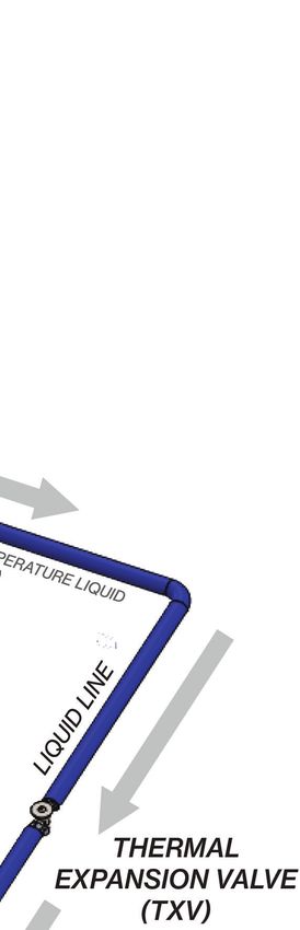
GENERAL SAFETY INFORMATION
PRECAUTIONS                                                        GROUNDING INSTRUCTIONS
    **DO NOT USE THIS UNIT IF ANY PART HAS BEEN UNDER WATER.**     This heat pump water heater must be grounded in accordance
Immediately call a qualified service agency to inspect the unit    with the National Electrical Code and/or local codes. These
and make a determination on what steps should be taken next.       must be followed in all cases. Failure to ground this water
                                                                   heater properly may also cause erratic control system operation.
If the unit is exposed to the following, do not operate heater
until all corrective steps have been made by a qualified service   This heat pump water heater must be connected to a
agency.                                                            grounded metal, permanent wiring system; or an equipment
                                                                   grounding conductor must be run with the circuit conductors
1. External fire.
                                                                   and connected to the equipment grounding terminal or lead
2. Damage.                                                         on the water heater.
3. Running without water .

     2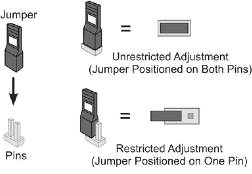
INTRODUCTION
Thank you for purchasing this heat pump water heater. Properly          This manual contains instructions for the installation, operation,
installed and maintained, it should give you years of trouble           and maintenance of the heat pump water heater (HPWH). It
free service.                                                           also contains warnings throughout the manual that you must
Abbreviations found In this Instruction Manual include:                 read and be aware of. All warnings and all instructions are
                                                                        essential to the proper operation of the HPWH and your safety.
 • HPWH - Heat Pump Water Heater                                        READ THE ENTIRE MANUAL BEFORE ATTEMPTING TO INSTALL
 • ANSI - American National Standards Institute                         OR OPERATE THIS WATER HEATING APPLIANCE.
 • ASME - American Society of Mechanical Engineers                      Detailed installation diagrams are in this manual. These
                                                                        diagrams will serve to provide the installer with a reference
 • NEC - National Electrical Code
                                                                        for the materials and suggested methods of piping. IT IS
 • NFPA - National Fire Protection Association                          NECESSARY THAT ALL WATER PIPING AND THE ELECTRICAL
 • AHRI - Air-conditioning, Heating and Refrigeration Institute         WIRING BE INSTALLED AND CONNECTED AS SHOWN IN THE
                                                                        DIAGRAMS.
QUALIFICATIONS
                                                                        Particular attention should be given to the installation of the
QUALIFIED INSTALLER OR SERVICE AGENCY:                                  system (tank) temperature control. See page 17.
Installation and service of this water heater requires ability
equivalent to that of a Qualified Agency (as defined by ANSI
below) in the field involved Installation skills such as plumbing,
electrical supply are required in addition to electrical testing
skills when performing service.
This heat pump water heater contains R-134a refrigerant and
is regulated as a stationary refrigeration appliance under Section
608 of the Clean Air Act. Servicing of the refrigeration circuit
must only be performed by agencies or individuals possessing
Type II or Universal certification as defined in Section 608 of
the Clean Air Act.
                                                                        Be sure to turn off power when working on or near the electrical
ANSI Z223.1 2006 Sec. 3.3.83: “Qualified Agency” - “Any                 system of the heat pump. Never touch electrical components
individual, firm, corporation or company that either in person          with wet hands or when standing in water. When replacing
or through a representative is engaged in and is responsible            fuses always use the correct size for the circuit.
for (a) the installation, testing or replacement of gas piping or
                                                                        The principal components of the HPWH are identified in the
(b) the connection, installation, testing, repair or servicing of
                                                                        Features And Components section of this manual on page 5.
appliances and equipment; that is experienced in such work;
                                                                        The rating label on the HPWH also provides useful information.
that is familiar with all precautions required; and that has complied
                                                                        These references should be used to identify the heat pump, its
with all the requirements of the authority having jurisdiction.”
                                                                        components and optional equipment.
                                                                        2. The installation must conform with these instructions and the
                                                                        local code authority having jurisdiction and the requirements of
                                                                        the power company. In the absence of local codes, the installation
                                                                        must comply with the latest editions of the National Electrical
                                                                        Code, ANSI/NFPA 70 or the Canadian Electrical Code CSA C22.1.
                                                                        The National Electrical Code may be ordered from: National
                                                                        Fire Protection Association, 1 Batterymarch Park, Quincy, MA
                                                                        02269.
                                                                        The Canadian Electrical Code is available from the Canadian
PREPARING FOR THE INSTALLATION                                          Standards Association, 8501 East Pleasant Valley Road, Cleveland,
1. Read the “General Safety Information” section of this                OH 44131.
manual First and then the entire manual carefully. If you don’t         3. If after reading this manual you have any questions or do
follow the safety rules, the heat pump water heater may not             not understand any portion of the instructions DO NOT proceed
operate safely. It could cause DEATH, SERIOUS BODILY INJURY             with the installation. Call the toll free number listed on the
AND/OR PROPERTY DAMAGE.                                                 back page of this manual for technical assistance.

                                                                                                                                   3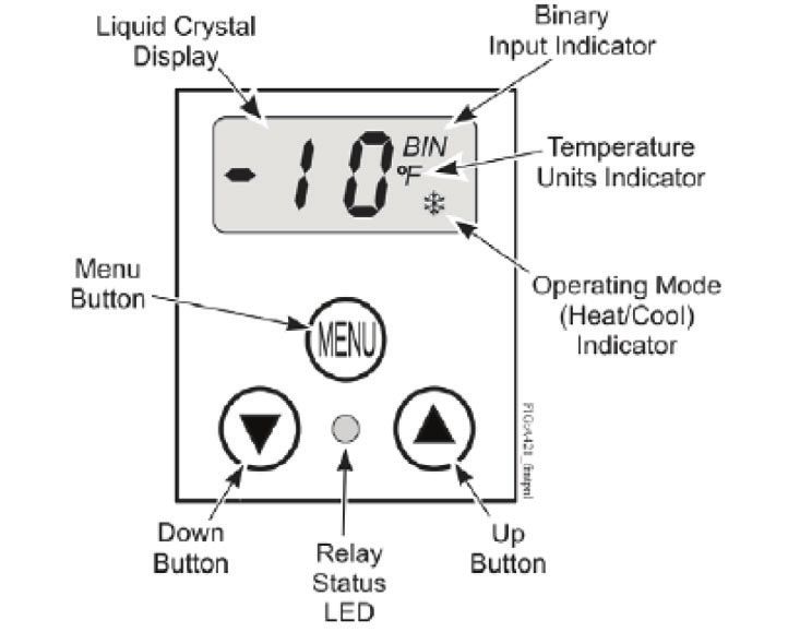
4. In order to expedite your request, please have full model            The Blower moves ambient air from the installed space or air
and serial number available for the technician.                         ducted to the HPWH from another location across the fins of
5. Carefully consider your intended placement and location              evaporator coil. The refrigerant absorbs heat from the air in
for the HPWH. See Locating The Water Heater on page 9.                  the evaporator. The refrigerant changes state (boils/evaporates)
                                                                        from a liquid state back into a gas (vapor) in the evaporator.
6. Installation and service of this HPWH requires ability
equivalent to that of a licensed tradesman or Qualified Agency          The refrigerant flows out of the evaporator through the Suction
in the field involved. See Qualifications on page 3.                    Line and into the Accumulator. The accumulator traps any
                                                                        liquid refrigerant the evaporator is unable to vaporize during
7. For installation in California the HPWH unit must be braced
                                                                        low temperature operating conditions. The accumulator prevents
or anchored to avoid falling or moving during an earthquake.
                                                                        liquid refrigerant from entering the compressor where it could
Instructions may be obtained from California Office of the State
                                                                        damage internal components.
Architect, 1102 Q Street, Suite 5100, Sacramento, CA 95811.
                                                                        Low temperature low pressure refrigerant gas (vapor) is drawn
8. Ensure the power supply voltage and phase at the job site
                                                                        out of the accumulator by the compressor. The compressor
matches the power requirements on the HPWH rating label
                                                                        increases the pressure and temperature of the refrigerant gas
before installation begins. Energizing the HPWH with the wrong
                                                                        circulating it to the condenser again where the refrigeration
voltage or phase will cause permanent damage to the unit.
                                                                        cycle starts over or continues.
PRINCIPLE OF OPERATION                                                  AIR TEMPERATURE RANGE
The units covered by this Instruction Manual are commercial
                                                                        The entering air temperature operating range for the HPWH is
modular air-to-water heat pump water heaters (HPWH).
                                                                        40°F to 120°F (4°C to 49°C).
Operation of the HPWH is similar to that of a package air
                                                                        When the HPWH is operating properly the air temperature
conditioning system. The primary difference in operation is that
                                                                        drop through the evaporator (heat exchanger) will be
the HPWH unit utilizes the heat removed from the conditioned
                                                                        approximately 12°F to 20°F (7°C to 11°C).
or ambient space to heat water where package air conditioning
systems discard this heat outdoors. Recovering and using                WATER TEMPERATURE RANGE
this waste heat increases the overall energy efficiency of the
                                                                        The inlet (entering) water temperature operating range for the
building.
                                                                        HPWH is 40°F to 140°F (4°C to 60°C). The HPWH will heat potable
THE REFRIGERATION CYCLE                                                 water up to 160°F. When the HPWH is operating properly the
                                                                        water temperature rise through the condenser (heat exchanger)
Refer to Figure 1 and the AIR TO WATER CYCLE on pages 5 & 6             will be approximately 8°F to 12°F (4°C to 7°C).
for the location of components mentioned in this section.
Refrigerant is circulated through the refrigeration circuit by          REFRIGERANT CHARGE
a Compressor. The refrigerant is a high temperature high                The HPWH is factory-charged with R-134a refrigerant. The
pressure gas when it leaves the compressor. Refrigerant flows           refrigerant charge is weighed in at the factory. See Table 9 on
from the compressor through the Hot Gas Line to the Condenser.          page 32. It should not be necessary to add or remove refrigerant
The condenser is a refrigerant-to-water heat exchanger with             during installation or start up.
two circuits, refrigerant flows through one circuit and water
through the other. The high temperature refrigerant gas transfers
                                                                        EQUIPMENT DISPOSAL
its heat to the water flowing through the condenser. As the             This heat pump water heater contains R-134a refrigerant and
refrigerant gas cools inside the condenser it changes state             is regulated as a stationary refrigeration appliance under
(condenses) from a gas to a liquid. An integrated hot                   Section 608 of the Clean Air Act. Disposal of this unit must be
water circulator pump is provided from the factory which                performed in accordance with the provisions in Section 608 of
is sized for a short pipe run, this pump circulates water               the Clean Air Act and any state or local regulations that may
through the condenser.                                                  also apply. See Qualifications on page 3.
Refrigerant leaving the condenser is a medium temperature
high pressure liquid. It flows through the Liquid Line to the
Thermostatic Expansion Valve. The thermostatic expansion
valve (TVX) flashes the liquid to a gas/liquid state which helps
to ensure all of the refrigerant is in a gaseous state by the time it
exits the evaporator to protect the compressor. The evaporator
is a tube-and-fin constructed coil. It is an air- to-refrigerant heat
exchanger with refrigerant flowing through the tubes and air
flowing across the fins.

     4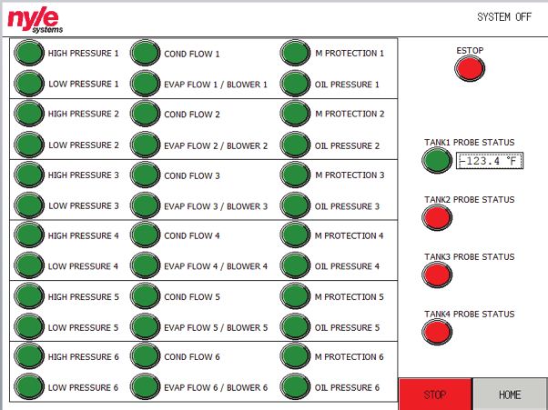
FEATURES & COMPONENTS

PRODUCT ILLUSTRATION
                                                         ACCUMULATOR
                                THERMOSTATIC
            RETURN AIR
                               EXPANSION VAVLE
                INLET
                                    (TXV)
            (AIR FILTERS)
                                                                         RECIEVER
                                                                                        BLOWER

         EVAPORATOR
      (HEAT EXCHANGER)
    (AIR TO REFRIGERANT)

          COMPRESSOR

                                                                                         SUPPLY AIR
                                                                                          OUTLET
        CONDENSER
     (HEAT EXCHANGER)
  (REFRIGERANT TO WATER)

                                                                                 ELECTRICAL PANEL

                CONDENSATE            BLOWER
                  DRAIN               MOTOR
                                                  WATER OUTLET     WATER INLET
                                               Figure 1

 Component Refrigeration Circuit         Refrigerant State       Component Water Circuit
 Compressor                              Gas                     Water Inlet
 Condenser (Heat Exchanger)              Gas to Liquid           Condenser (Heat Exchanger)
 Receiver                                Liquid                  Water Outlet
 Thermostatic Expansion Valve (TXV)      Liquid
 Evaporator (Heat Exchanger)             Liquid to Gas
 Accumulator                             Gas / Liquid

                                                                                              5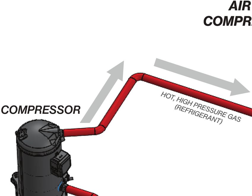
AIR TO WATER CYCLE

   6
ROUGH IN DIMENSIONS

                                                                        Figure 2
PERFORMANCE    SPECIFICATIONS
 PERFORMANCE SPECIFICATIONS
 TABLE 1

                                               Performance                                    Dimensions                     Weight
                               Water
                                                                        Volume

                                           Water
                                                                        (CFM)

                                Flow                     Cooling                   Inlet
                                                                          Air

         Model Number                     Heating                                                                     Dry      Operating
                                Rate                     Capacity                 Outlet   Length   Width   Height
                                          Capacity                                                                   Weight     Weight
                               (GPM)                                              Water      A       B        C
                                                                                                                     (LBS)      (LBS)
                                            BTUH           BTUH                   (FPT)

            AHPA-25              5.4       27,450          21,200       1,250      ¾”       45”      34”    24 ⅞”     300         310

            AHPA-60              13        63,225         48,425        2,800       1”      64”     30 ¾”   34 ⅝”     500         520

            AHPA-90              20        110,725         83,625       2,800      1 ½”     70”     30 ¾”   40 ¼”     750         775

           AHPA-125              28        144,275        108,500       4,500      1 ½”     84”     40”     36 ⅛”    1,200       1,240

           AHPA-185              40        224,675        172,375       4,500      2”      96 ⅛”    33 ¾”   45 ⅛”    1,350       1,410

           AHPA-250              50        272,450        218,000       8,000      2”      84 ½”    55 ⅜”    70”     2,100       2,175

All dimensions are in Inches. Weights are approximate shipping weights.
*Performance rating at 75° F Entering Air Temperature and 60% Relative Humidity
*Water Heated from 50° F to 150° F
COP = Coefficient Of Performance
Standard Voltage on AHPA-25 & AHPA-60 models - 208/230 V, 1-phase, 60Hz
Standard Voltage on AHPA-90 - AHPA-250 models - 208/230 V, 3-phase, 60Hz
Other power options are available upon request

LOCATION OF THE HEATED WATER CONNECTIONS COULD VARY BY UNIT,
SEE MANUFACTURER DOCUMENTS FOR EACH INDIVIDUAL UNIT.

                                                                                                                                         7
INSTALLATION REQUIREMENTS
Read all installation requirements in this manual before AIR TEMPERATURE
installation begins. The installation must conform to these
ENTERING AIR TEMPERATURE
instructions and all local and national code authority having
jurisdiction. The return (entering) air temperature range of operation for
the unit is 40° - 120°F (4.4°C to 48.9°C). The air temperature
Costs to diagnose, perform service and repair damage caused
drop (Delta T - ΔT) through the evaporator (heat exchanger)
by installation errors are not covered under the limited warranty.
will be approximately 12°F to 20°F (7°C to 11°C).
Costs to correct installation errors are not covered under the
If the entering air temperature is outside this operating range
limited warranty.
the HPWH unit’s Ambient Air Limit Thermostat will discontinue
WATER TEMPERATURE heating operation until the entering air temperature returns
to this operating range. (If the evaporator is equipped with
MAXIMUM SYSTEM TEMPERATURE Heating Elements, they will kick on to bring up the ambient
The HPWH units covered in this manual are capable of temperature).
maintaining a maximum system/storage tank temperature
LOCATING THE WATER HEATER
of 150°F (66°C). Some commercial water heating applications
may require higher temperatures. Install a booster
water heater downstream from the storage tank for
temperatures above 150°F (66°C). See Figure 8 on page 16
INLET & OUTLET WATER TEMPERATURE
The inlet (entering) water temperature operating range for
the HPWH is 40°F to 140°F (4.4°C to 60°C). The water temperature
rise (Delta T - ΔT) through the condenser (heat exchanger) will
be approximately 8°F to 12°F (4°C to 7°C). INDOOR/OUTDOOR INSTALLATION
Outlet water temperatures up to 152°F (67°C) are possible (Milder Climates)
during normal operation. Exposure to water temperatures Carefully choose a location for the HPWH unit. Placement is a very
this high can cause serious bodily injury or death. See Mixing important consideration for optimal performance and safety.
Valves and Table 5 on pages 11 & 12.
Locate the HPWH near a floor drain. The unit should be
Service & Installation Notes: located in an area where leakage from the HPWH unit or the
If the inlet (entering) water temperature is outside the operating storage tank it is connected to will not result in damage to the
temperature range for extended periods the control area adjacent to the water heater or to lower floors of the
system may lock out on high or low refrigerant pressure structure. See Unit Placement on page 14.
switch events/trips. FREEZING TEMPERATURES
When the control system locks out on a refrigerant pressure The HPWH unit must not be installed in space where freezing
switch event the compressor will stop running, the blower and temperature will occur, without a low ambient air kit. Exposure
circulation pump (on models equipped with factory installed to freezing ambient temperatures below 32°F (0° C) may result
pump) will continue to operate. This is a hard lock out condition. in severe damage to internal components. Damage caused by
The control system is manually reset by cycling power to the exposure to freezing temperatures is not covered under the
HPWH off and then on again. limited warranty.
The tank thermostat must not be set any higher than 150°F COASTAL REGIONS
(66°C) to prevent control system lock outs.
When the HPWH will be installed within 5 miles of a seacoast
Ground water temperatures can fall below 50°F (10°C) the optional Corrosive Duty Package is recommended. The
for extended periods during winter months in many regions. corrosive duty package includes a stainless steel cabinet,
For this reason the cold water supply lines and should not (Ecoating is standard on the evaporator). Damage caused to
be connected directly to the HPWH inlet or T fitted into the units not equipped with the corrosive duty package in coastal
inlet (return) water piping. The cold water supply lines should regions is not covered under the limited warranty.
be connected directly to the storage tank only. See the Piping
HEAT SOURCE
Diagrams on page 34 in this manual for more information.
The HPWH unit should be located where there is an adequate
source of ambient heat and where the cooling benefit can be
8utilized when possible. If installation in a space with an ELECTRICAL REQUIREMENTS
adequate heat source is not possible the HPWH unit can be
Ensure the power supply voltage and phase at the job site
ducted to/from another space such as a boiler room or to the
matches the power supply ratings listed on the HPWH data
outdoors where sufficient heat is available. See Air Flow and
sticker label BEFORE INSTALLATION BEGINS.
Ducting on page 17.
The installation must conform with these instructions and the
CONDITIONED SPACE
local code authority having jurisdiction and the requirements
When installed in a conditioned space ducting supply of the power company. In the absence of local codes,
(outlet) air to an alternate location may be necessary to the installation must comply with the current editions of
avoid over-cooling of the space where the HPWH is installed the National Electrical Code, ANSI/NFPA 70 or the Canadian
or provide spot cooling in areas for comfort and/or to offset Electrical Code CSA C22.1.
cooling load. See Building Air Pressure, Air Flow and Ducting
Voltage applied to the HPWH should not vary more than +5%
on page 17.
to -10% of the voltage requirement listed on the HPWH rating
UNCONDITIONED SPACE label for satisfactory operation.
When installed in an unconditioned space ducting return MINIMUM CIRCUIT AMPACITY & MAXIMUM FUSE SIZE
(inlet) air from an alternate location may be necessary to
Table 2 provides the MCA (Minimum Circuit Ampacity) and
access an adequate or greater source of heat for optimal
MFS (Maximum Fuse Size). Use MCA to select the minimum
efficiency. See Building Air Pressure, Air Flow and Ducting on
field wires size to power the unit and MFS to select the maximum
page 17.
fuse size for over current protection as follows:
CLEARANCES MCA = C x 1.25 + M + P
To ensure optimal performance a minimum of 30 inches MFS = C x 2.25 + M + P
clearances required from the back, left and right sides of the Where:
HPWH unit and any wall obstruction. A minimum of 36 inches
clearance on the front of the unit for access to the control box. C - Compressor RLA
When installed on an equipment pad the HPWH must be level M - Blower Motor FLA
and elevated at least 6” above floor to avoid dust and debris P - Pump FLA
and permit connection of the condensate line and trap.
TABLE 2 - VOLTAGE & AMPERAGE RATINGS
Compressor Fan Motor Blower Motor Pump Fan HPWH Blower HPWH
Model Volts/Phase/HZ
RLA MCC HP FLA HP FLA HP FLA MCA MFS MCA MFS
208-230/1/60 16.0 25.0 2.5 2.3 0.17 6.50 1.0 1.40 24 25 28 30
AHPA-25
208-230/3/60 9.0 14.0 2.5 1.1 0.17 4.00 1.0 1.40 14 15 17 20
440-480/3/60 4.5 7.0 2.5 0.6 0.17 2.00 1.0 1.40 8 10 10 15
575/3/60 3.8 6.0 3.0 1 0.50 1.20 1.0 1.40 8 10 8 10
208-230/1/60 28.2 44.0 5.5 3 0.33 6.20 1.5 1.90 41 15 44 15
208-230/3/60 20.2 31.5 6.0 1.8 0.33 4.40 1.5 1.90 29 30 32 35
AHPA-60
440-480/3/60 9.1 14.2 6.0 1 0.33 2.20 1.5 1.90 15 20 16 20
575/3/60 7.1 11.0 6.0 1 0.50 1.80 1.5 1.90 12 15 13 15
208-230/3/60 35.3 55.0 10.0 2.1 0.33 4.40 1.5 1.90 49 50 51 60
AHPA-90 440-480/3/60 17.9 28.0 10.0 1 0.33 2.20 1.5 1.90 26 30 27 30
575/3/60 11.5 18.0 10.0 1 0.50 1.80 1.5 1.90 18 20 19 20
208-230/3/60 48.1 75.0 13.0 3 0.75 8.40 3.0 4.90 69 70 74 80
AHPA-125 440-480/3/60 21.8 34.0 13.0 1.5 0.75 4.20 3.0 4.90 34 35 37 40
575/3/60 18.6 29.0 13.0 1.2 0.75 3.30 3.0 4.90 30 35 32 35
208-230/3/60 73.1 114.0 20.0 3 1.00 8.40 3.0 4.90 100 110 105 110
AHPA-185 440-480/3/60 30.1 47.0 20.0 1.5 1.00 4.20 3.0 4.90 45 50 47 50
575/3/60 24.4 38.0 20.0 1.2 1.00 3.30 3.0 4.90 37 40 39 40
208-230/3/60 90.7 127.0 25.0 2.7 0.50 13.53 5.0 2.00 119 125 129 150
AHPA-250 440-480/3/60 45.7 64.0 25.0 1.2 0.50 6.12 5.0 1.00 60 70 65 70
575/3/60 37.9 65.0 25.0 1 0.50 5.30 5.0 1.00 50 60 54 60
RLA: Running Load Amps LRA: Locked Rotor Amps MCC: Maximum Continuous Current
FLA: Full Load Amps HP: Horse Power MCA: Minimum Current Ampacity
MFS: Maximum Fuse Size
All Shown MFS Values Are Rounded up to the Nearest Common Fuse Size.
9MINIMUM WIRE SIZE
Allowable Ampacities of Insulated Conductors
Single-phase heat pump water heaters are two wire circuits.
Three-phase heaters are three wire circuits. In addition to the
foregoing, a grounded conductor is required. Not more than
three conductors in raceway, cable, or earth (directly buried),
based on ambient temperature of 30°C (86°F)
TABLE 3
+The load current rating and the over current protection for these conductors shall not exceed 15 amperes for 14 AWG. 20 amperes for 12 AWG and 30 amperes for 10
AWG copper; or 15 amperes for 12 AWG and 25 amperes for 10 AWG aluminum and copper-clad aluminum.
*For dry locations only. See 75°C column for wet locations.
10WATER PIPING CLOSED WATER SYSTEMS
Read all installation requirements in this manual before Water supply systems may, because of code requirements or
installation begins. such conditions as high line pressure, among others, have
The water piping installation must conform to these instructions installed devices such as pressure reducing valves, check
and to all local and national code authority having jurisdiction. valves, and back flow preventers. Devices such as these cause
the water system to be a closed system.
Costs to diagnose, perform service and repair damage caused
by installation errors are not covered under the limited warranty. THERMAL EXPANSION
Costs to correct installation errors are not covered under the As water is heated, it expands (thermal expansion). In a closed
limited warranty. system the volume of water will grow when it is heated. As the
MINIMUM PIPE SIZE volume of water grows there will be a corresponding increase
in water pressure due to thermal expansion. Thermal expansion
The inlet (return) and outlet (supply) water piping installed
can cause premature failure (leakage) of storage tanks, water
between the HPWH unit and the storage tank must not be
heaters and HPWH components such as the condenser. Leakage
smaller than the water connection sizes on the HPWH. See
caused by thermal expansion is not covered under the HPWH
Table 4, below, for water line connection sizes and water flow
limited warranty.
rates.
Thermal expansion can also cause intermittent Temperature-
Water line sizing is a critical installation requirement. Installing
Pressure Relief Valve operation: water discharged due to
undersized water piping between the storage tank and the
excessive pressure build up. The Temperature-Pressure Relief
HPWH unit will cause insufficient water flow and will have an
Valve is not intended for the constant relief of thermal
adverse impact on performance and equipment life.
expansion.
TABLE 4 A properly sized thermal expansion tank must be installed on
Water Connection and Flow all closed systems to control the harmful effects of thermal
Unit
Water Flow Rate Connection Size expansion. Contact a local plumbing service agency to have a
(GPM) (Inches)
thermal expansion tank installed on all closed water systems.
AHPA-25 5.4 ¾”
AHP0060 13 1” MIXING VALVES
AHPA-90 20 1 ½”
AHPA-125 28 1 ½”
AHPA-185 40 2”
AHPA-250 50 2”
PIPE SUPPORT
All water piping must be properly supported per local code
requirements.
PIPE INSULATION
All piping installed between the HPWH unit and the storage
tank must be insulated.
COLD WATER SUPPLY
Water heated to a temperature which will satisfy clothes washing,
Cold water supply lines should not be connected directly to dish washing, and other sanitizing needs can scald and cause
the HPWH inlet or T fitted into the inlet (return) water piping. permanent injury upon contact. See Table 5, page 12.
The cold water supply lines should be connected directly to
the storage tank only. See Inlet & Outlet Water Temperature Some people are more likely to be permanently injured by hot
on page 8 and Figure 7 and Figure 8 on page 16. water than others. These include the elderly, children, the in-
firm and the physically/mentally disabled. Table 5 shows the
WATER PRESSURE approximate time-to-burn relationship for normal adult skin.
If anyone using hot water provided by the water heater being
System water pressure should be maintained between 40 and installed fits into one of these groups or if there is a local code
60 PSI. Local code may require, and the manufacturer or state law requiring a certain water temperature at the point
recommends, installing a pressure reducing valve (PRV) in of use, then special precautions must be taken.
the cold water supply to the building to maintain consistent
water pressure. In addition to using the lowest possible temperature setting
that satisfies the demand of the application a Mixing Valve
11should be installed upstream from the building fixtures or at
the hot water taps to further reduce system water temperature.
Mixing valves are available at plumbing supply stores. Consult
a Qualified Installer or Service Agency. Follow the mixing valve
manufacturer’s instructions for installation of the valves.
TABLE 5
of all connected appliances must be factored when choosing
CONDENSATE REMOVAL a T&P valve for the storage tank.
The HPWH unit produces condensate which must be The pressure rating of the T&P valve should always be rated
discharged. If there is no drain easily accessible, a condensate equal to or below the working pressure rating of the storage
lift pump must be installed to discharge the condensate to a tank or water heater, whichever rating is lower.
remote location. See Condensate Drain Line on page 16 Contact the manufacturer of the storage tank for assistance
for installation instructions. in sizing of a temperature and pressure relief valve. Follow the
storage tank manufacturer’s instructions regarding the proper
CONTAMINATED WATER installation of these products.
This HPWH unit must not be used to heat any fluid other than TANK SELECTION
water. Corrosive chemicals must not be introduced into the
waterways in this HPWH unit. The HPWH unit is not an instantaneous water heater and must
be connected to a storage tank. Storage tank configurations
must meet these criteria:
1. The HPWH must not be connected directly to a standard
gas or electric water heater.
2. If the HPWH is connected to a used storage tank, the tank
should be thoroughly cleaned of scale and sediment
before the HPWH is installed.
TEMPERATURE-PRESSURE RELIEF VALVE 3. Connection ports used on the storage tank must permit
This heat pump water heater should only be connected to a the recommended flow rate through HPWH. The
storage tank with a properly rated/sized and certified connection ports used on the storage tank must not
combination temperature - pressure relief valve. The valve be smaller than the inlet outlet connection sizes on the
must be certified by a nationally recognized testing laboratory HPWH unit. See Table 4 on page 11.
that maintains periodic inspection of production of listed 4. Water heated by the HPWH should be returned to the
equipment of materials as meeting the requirements for Relief tank at a location that is above the level of the tank’s cold
Valves for Hot Water Supply Systems, ANSI Z21.22 • CSA 4.4, water inlet and/or the heat pump’s inlet source.
and the code requirements of ASME.
5. The HPWH unit’s inlet and outlet lines to the storage tank
When the HPWH unit is connected to a storage tank a should be dedicated. Example: no other line (such as a
temperature and pressure relief valve must be installed in building re-circulating loop or cold water supply) should
the designated opening for the T&P valve per the storage be connected to the HPWH unit’s inlet or outlet water
tank manufacturer’s requirements. The T&P valve’s Btu/hr lines.
rating must be equal to or greater than the total heating input
SOLAR TANKS
rating of all water heaters connected to the storage tank. If
more than one water heating appliance is connected to the Solar tanks should be used with caution. Some solar tanks
storage tank the aggregate total of all heating input ratings with top connections have dip tubes which may significantly
reduce the efficiency performance of the HPWH unit.
12Before using any solar tank in this application, contact your • When using a forklift to raise the HPWH unit ensure the
representative or call the toll free technical support number forks are positioned correctly between the runners on the
on the back cover of this manual for further assistance. bottom of the HPWH unit. See Figure 6.
• The HPWH unit must be lifted from the front side only
CONTAMINATED AIR
when using a forklift to raise the unit. See Figure 6.
The supply (outlet) air from a HPWH installed in a garage or a
STORAGE RECOMMENDATIONS
unit drawing return (inlet) air from a garage or any area where
solvents or other chemicals that emit potentially harmful The HPWH units should be stored indoors. Do not stack units
fumes are stored or automobiles are located must never be or stack other construction materials on the units while in
ducted to any other space inside the building structure. This storage.
would include all occupied and unoccupied spaces such as attics The HPWH units contain electrical/electronic components
or basements. Potentially harmful fumes and vapors could be and should only be stored in conditions between 0ºF to 110°F
introduced into occupied spaces. See Unit Placement on page 14. (-17°C to 43°C) and 5 to 95 percent relative humidity. Electrical
components are not moisture-tolerant.
Note: The limited warranty does not cover damage to the
unit or controls due to negligence during storage.
The pictures may appear different than your actual unit. all
information and reference to lifting applies to all of our models
STORAGE & HANDLING
The heat pump water heaters covered in this manual are
stationary refrigeration appliances. Careful handling is
necessary to prevent internal damage.
FIGURE 4
• IMPORTANT: Do not remove, cover or deface any permanent
instructions, wiring diagrams, labels, or the rating label from
the outside cabinet or the inside panels on the HPWH unit.
• Do not tilt the unit beyond 45° at any time. All internal FIGURE 5
components are braced from the base of unit. Tilting
may compromise the refrigeration piping inside unit and
cause refrigerant leaks.
• Do not hoist the unit with chains or straps unless spreader
bars are furnished and used as depicted in Figure 4 and Figure
5. The side panels and roof of the unit are not constructed to
handle significant force from the sides or above.
• The HPWH unit is heaviest on the compressor side (left side
when facing the front of the unit). See Figure 4 and Figure 6.
FIGURE 6
13INSTALLATION
REQUIRED ABILITY SERVICE TOOLS
Installation and service of the HPWH unit requires ability See Qualifications on page 3 regarding regulations and
equivalent to that of a qualified agency in the field involved. certifications required under Section 608 of the Clean Air Act
Plumbing, ducting and electrical work are required. See before servicing the refrigeration circuit.
Qualifications on page 3. 1. Refrigeration manifold gauges.
GENERAL 2. Refrigeration charging scale.
The installation must conform with these instructions and the 3. Refrigeration vacuum pump.
local code authority having jurisdiction. In the absence of local 4. Refrigerant recovery machine.
codes, the installation must comply with the latest editions of
5. Refrigerant reclamation storage tank.
the National Electrical Code, ANSI/NFPA 70 or the Canadian
Electrical Code CSA C22.1. The National Electrical Code may UNIT PLACEMENT
be ordered from: National Fire Protection Association, 1
Whether replacing existing water heating equipment or
Batterymarch Park, Quincy, MA 02269. The Canadian Electrical
installing the HPWH in new construction, the following critical
Code is available from the Canadian Standards Association,
points must be observed: The HPWH unit:
8501 East Pleasant Valley Road, Cleveland, OH 44131.
1. Should be installed near a floor drain for condensate removal.
DO NOT start the HPWH unit or test the electrical system before
it is connected to the water system, purged of air and filled 2. The HPWH, storage tank and water heater(s) should be
with water. See Start Up on page 22. located in an area where leakage will not result in damage
to adjacent area or to lower floors in the building structure.
See Features And Components on page 5 to identify the
principal components of the HPWH. (Some units will vary) 3. The HPWH unit must be level for proper condensate
drainage. Shim the channel type skid base, pad or floor as
REQUIRED TOOLS & MATERIALS necessary if leveling is required.
INSTALLATION & START UP TOOLS 4. Should be installed close to the point of major hot water
1. All tools common to installation and service of commercial usage and power supply.
electric water heaters such as hand tools, pipe cutter and torch. 5. Should be located so that hot water piping and branch
2. Heat transfer compound (paste) such as Honeywell part circuit wiring will be as short as possible.
number 107408 or equivalent. CEILING SUSPENSION
3. Electrical switch lock out device - used to secure disconnect Because warm air rises, a drop ceiling or suspended from ceiling
switches/breaker panels while servicing. configuration is preferred to take advantage of higher ambient
4. Electronic thermometer including: temperatures. The HPWH may be suspended from the ceiling
using a safe and properly designed support. The sides and top
• Four (4) thermocouple sensors capable of measuring surface
of the cabinet are not designed to support the weight of the
temperatures on water or refrigerant piping up to 2
unit.
inch diameter.
Do not attach straps or bars directly to the sides or top of the
• Two (2) thermocouple sensors capable of measuring
cabinet. If the HPWH is suspended, it must be supported from
ambient air temperature.
underneath.
• Temperature range 32°F - 210°F (0°C - 100°C).
MOUNTING FRAME
5. Volt-Ohm Multi Meter - capable of measuring:
The mounting frame must support the length, width, and
• AC Voltage up to 600 VAC. weight of the HPWH unit. The weight of the HPWH unit must
• DC Voltage up to 24 VDC. be evenly dispersed across the footing channels on the bottom
of the unit. See Table 1 on page 7 for unit dimensions and
• Ohms up to 2,000,000 ohms.
weights.
• Continuity.
NOTE: A qualified engineer should design and size the
6. AC amp meter - capable of measuring: structural components of the mounting frame and the
• AC amperage up to 200 amps. appropriate hangers. Structural channels in a field-provided
frame should be mounted perpendicular to the unit’s footing
7. Calculator. channels.
14The following critical points must be observed when the
HPWH unit is suspended from the ceiling:
1. Hanging rods must not obstruct access doors.
2. VIBRATION ISOLATORS ARE REQUIRED to prevent
transmission of mechanical vibration into the building
structure. Selection of suitable isolators should be made
by a qualified engineer.
3. Installation must meet local seismic restraint requirements.
PAD MOUNTING
The HPWH may be pad mounted. Vibration isolator mounts Turn on power to the HPWH momentarily and measure the voltage
MUST BE placed between the unit and the equipment pad to to the primary winding of the transformer at the F3 fuse block. If the
prevent mechanical vibration transmitting into the building measured voltage is above 215 VAC no changes are necessary.
structure. Selection of appropriate vibration isolators should
If the measured voltage is 215 VAC or less, then the primary
be made by a qualified engineer. Unit must be level and
leads of the transformer must be changed from the 230 VAC
elevated at least 6” above floor to avoid dust and debris from
tap to the 208 VAC tap. Do this by disconnecting the orange
entering the unit and permit connection of the condensate
wire from the transformer primary terminal and replacing
trap. See Condensate Drain Line on page 16.
with the red wire. Before reapplying power, ensure orange
ELECTRICAL CONNECTIONS lead is safely isolated with a wire nut and electrical tape.
CORRECT VOLTAGE AND PHASE WATER CONNECTIONS
The HPWH units covered by this instruction manual can be
Water piping must be installed in accordance with the instructions
ordered with multiple power supply voltage and phase
in this manual and all local plumbing codes having jurisdiction.
configurations. Ensure the power supply voltage and phase
See Figure 7 and Figure 8 on page 16 and the Piping Diagrams
at the job site matches the power supply ratings listed on the
on page 34 as a reference for these instructions.
HPWH rating label BEFORE INSTALLATION BEGINS.
INSTALLATION INSTRUCTIONS
Voltage applied to the HPWH should not vary more than +5%
to -10% of the voltage requirement listed on the HPWH rating 1. This HPWH unit is not designed to supply hot water directly
label for satisfactory operation. to hot water fixtures. The HPWH unit must be installed with a
separate storage tank as shown in the water piping diagrams
Energizing the HPWH with the wrong voltage and/or phase
in this instruction manual.
may cause permanent damage to HPWH components.
Damage resulting from applying the wrong power supply 2. Water lines installed between the storage tank and the
voltage or phase to the HPWH is not covered under the HPWH unit MUST NOT be less than the water pipe
limited warranty. connection sizes on the unit. See Table 4 on page 11.
BRANCH CIRCUIT DISCONNECT SWITCH 3. The HPWH should be plumbed directly to the storage tank.
The power supply wiring and equipment grounding must be 4. The cold water supply must be connected directly to the
installed in accordance with local codes or, in the absence of storage tank at a low connection port on the storage tank
local codes, the National Electrical Code, ANSI/NFPA 70 or the on single tank and two tank preheat piping configurations
Canadian Electrical Code, CSA C22.1. for optimal efficiency. See Figure 7 and Figure 8 on page 16.
Install an adequately fused disconnect switch as close to the 5. The cold water supply MUST NOT be connected the inlet
units possible. See unit rating label for maximum fuse size (entering/return) water line to the HPWH unit.
(MFS). 6. The outlet (supply) water from the HPWH unit should
Run the power supply lines from the disconnect to the control connect to a middle or lower port on the storage tank.
box at the side panel of the unit. Connect the lines to the 7. The inlet (return) water from the HPWH unit should connect
terminals on input side of power distribution block L1 & L2 for to a port on the storage tank lower than the outlet.
single phase and L1, L2 & L3 for three phases. Connect ground
8. A heat trap should be installed between the storage tank
wire to ground lug.
and the backup water heater on two tank preheat systems.
TRANSFORMER CONFIGURATION 208 VAC MODELS See Piping Diagram on page 34.
AHPA-25 & AHPA-60 Only 9. A T&P valve must be installed in the designated opening
The transformer leads must be changed on units connected on the storage tank per the tank manufacturer’s requirements.
to a 208 VAC power supply as described on this page. See Temperature - Pressure Relief Valve on page 12.
1510. For optimal performance minimize the equivalent length the peak water flow rates through the water heating system. See
of water piping between the HPWH and storage tank. Piping Diagrams on page 34 for detailed piping diagrams.
11. Building hot water recirculation loop should be
connected to the inlet of the backup water heater on
two tank preheat configurations or to the storage tank on
single tank configurations. The recirculating pump MUST
BE controlled by a field supplied thermostat installed in
the building recirculation return line near the storage
tank or back up heater. The thermostat should stop pump
operation the moment the recirculation line is hot.
12. Use swing-type check valves (not spring-loaded types) on
the water outlet lines of all HPWH units plumbed in parallel
to prevent hot water short-circuiting.
13. Water lines shared by parallel HPWH units must be large
enough to handle combined water flows. Flow rates
through the heat pumps and tank(s) must be balanced. FIGURE 8
See Table 1 on page 8 for HPWH unit flow rates.
MULTIPLE TANK PRE HEAT CONFIGURATION
14. All components in the hot water supply system must be
When water temperatures above 150°F (66°C) are required the
adequately sized to meet peak water flow requirement
HPWH and storage tank are piped in series (upstream) with a
15. When the HPWH unit is installed above the storage tank install backup water heater. See Water Temperature on page 9. The
a Tee fitting at a high point in the outlet water line leaving backup water heater will raise the temperature of the
the unit. Install a purge valve, or if required by local code, a preheated water to the final system temperature required.
T&P valve (temperature and pressure relief) in a branch of Figure 8 shows a typical preheat piping configuration.
the Tee fitting that can be used to purge air from the HPWH
unit during start up. See Figure 7 and Figure 8. CONDENSATE DRAIN LINE
16. DO NOT install a (T&P) relief valve in the outlet line of the The HPWH unit must be plumbed to permit condensate
HPWH unit unless required by local code. drainage. Drain piping connected to the HPWH unit should
17. Dielectric unions should be installed at the inlet and outlet be a minimum 3/4 inch PVC or equivalent. A condensate trap
water lines to the HPWH unit. must be used to overcome the internal vacuum to permit
proper drainage. See Figure 9 below for recommended drain
18. All HPWH water piping must be insulated. trap dimensions.
The condensate must be discharged to a suitable drain. If a
drain is inaccessible, use a condensate pump.
FIGURE 9
FIGURE 7
STANDARD TANK THERMOSTAT
SINGLE TANK CONFIGURATION Standard tank thermostats (Aquastat) already installed in the
The HPWH must be plumbed to storage tank. The maximum storage tank may be used instead of the factory supplied
stored water temperature the HPWH unit can produce in the Digital Tank Thermostat if desired. Ensure the standard tank
storage tank is 150°F (66°C). Figure 7 shows a typical storage tank thermostat is installed the lower third of the tank. Wire the
piping configuration. Tank ports must be large enough to handle existing tank thermostat to the HPWH terminal strip.
16TEMPERATURE SENSOR INSTALLATION DUCT SIZING
The HPWH unit is shipped from the factory with a Digital Tank Supply and return air ducting must be sized properly to insure
Thermostat that includes a Temperature Sensor: adequate airflow. Table 6 & Table 7 on page 18 provide
1. Secure the Temperature Sensor inside a Sensor or Thermal requirements for the total equivalent supply and return
Well. duct lengths allowed. These tables are based on the most
common duct material options available today. Exceeding
2. Install the sensor well in the storage tank’s designated those maximum lengths will adversely affect the operation of
temperature control opening. It is not recommended to the heat pump.
install the temperature probe or sensor in the bottom or
the top of the tank. It is typical to install in the mid to lower DUCT INSULATION
portion of the tank. The cooled air from the HPWH may be below room dew point.
Do not install the temperature sensor near the cold water Insulate the supply duct to prevent dripping from moisture
supply connection to the storage tank to prevent short cycling. condensing on the duct.
It is not necessary to insulate return ducts unless the air in the
return duct is lower than the room air. Also consider insulating
all ductwork to reduce blower noise from the unit.
MAKE DUCT CONNECTIONS
Install all ductwork to and from unit in accordance with all
applicable codes. Duct construction must allow unit to operate
within the limits of the unit external static pressure as in the
HPWH unit’s performance and specification sheets. See Table
1 on page 7 also.
Use flexible connections to minimize duct-to-duct alignment
problems and noise transmission.
Install ductwork, accessory grilles, and plenums so that they
FIGURE 10 do not restrict access to filter and so they prevent dirt, dust,
and debris from settling in unit.
AIR FLOW AND DUCTING BUILDING AIR PRESSURE
GENERAL GUIDELINES When installing ducting to or from an alternate location
Review Locating The Water Heater on page 8, and this section (other than the installed space) both the supply (outlet) and
prior to connecting ductwork to the HPWH. See Features return (inlet) air may need to be ducted to prevent positive or
And Components on page 9 to locate components. negative building air pressure conditions within the installed
space.
NEGATIVE PRESSURE
Ducting supply air only to an alternate location, such as the
outdoors, may cause excessive negative air pressure inside the
building envelope.
Excessive negative pressure inside the building structure may
result in cold or hot air from outdoors being drawn inside the
building and place additional load on space heating and
cooling equipment. Negative air pressure in buildings can
also cause reverse flow in chimneys and gas vents.
POSITIVE PRESSURE
The supply (outlet) air from a HPWH installed in a garage or a Ducting return air only from an alternate location, such as the
unit drawing return (inlet) air from a garage or any area where outdoors, may cause excessive positive air pressure inside the
solvents or other chemicals that emit potentially harmful fumes building envelope.
are stored or automobiles are located must never be ducted to Excessive positive pressure inside the building structure may
any other space inside the building structure. This would include place additional load on space heating and cooling equipment
all occupied and unoccupied spaces such as attics or basements. by interfering with the delivery of conditioned air.
Potentially harmful fumes and vapors could be introduced into
occupied spaces. See Unit Placement on page 14.
17You can also read