Good practice guide Heat pump installation - April 2020 - Inspiring energy efficiency advancing renewable energy - EECA
←
→
Page content transcription
If your browser does not render page correctly, please read the page content below
Good practice guide
Heat pump installation - April 2020
Inspiring energy efficiency · advancing renewable energy
2

Good practice guide to
heat pump installation
Contents

                        Index of figures and tables                                                        5
                        1.0   Introduction                                                                 7
                        2.0   Heat pump systems                                                            8
                              2.1 Types of heat pump systems                                               8
                              2.2 Components of a heat pump                                               10
                              2.3 How a heat pump works                                                   12
                              2.4 Variable-speed (inverter) compressors                                   12
                        3.0   Heat pump performance                                                       13
                              3.1 Heat pump efficiency                                                    13
                              3.2 Energy rating label                                                     14
                              3.3 Effects of temperature on efficiency and heating capacity               14
                              3.4 Impacts of defrost cycle on efficiency and heat output                  15
                        4.0   Designing a heat pump system                                               16
                              4.1 Steps for designing a heat pump system                                 16
                              4.2 The importance of correct heat pump sizing                             16
                              4.3 Step 1: Determine requirements                                         17
                              4.4 Step 2: Calculate heat load requirement                                19
                              4.5 Step 3: Determine design temperature                                   20
                              4.6 Step 4: Select a system to meet requirements                           21
                              4.7 Step 5: Locate the units                                               21
                        5.0   Toolkit                                                                    25
                        6.0   Installing pipework                                                        26
                              6.1 Pipework installation                                                  26
                              6.2 Pipework pre-installation in new buildings                             33
                        7.0   Heat pump installation                                                     35
                              7.1 Pre-installation checklist                                             35
                              7.2 Installing the indoor unit                                             36
                              7.3 Installing the outdoor unit                                            39
                              7.4 Connecting piping to indoor and outdoor units                          41
                              7.5 Leak/pressure test                                                     44
                              7.6 Evacuation of the system                                               44
                        8.0   Refrigerants                                                               46
                              8.1 Refrigerant charging                                                   47
                              8.2 Labelling as record of service                                         47
                        9.0   Electrical requirements                                                    48
                              9.1 Installing electrical wiring                                           48
                              9.2 Outdoor unit connections                                               48
                              9.3 Nameplate                                                              49

EECA (Energy Efficiency and Conservation Authority) has taken reasonable steps to maintain current and accurate
information in this document. However, no guarantee is made as to the currency or accuracy of information.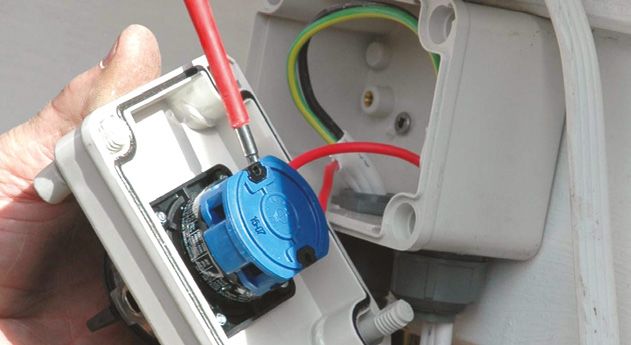
3

Contents

           10.0 Testing, commissioning and customer operating instructions   50
                10.1 Pre-commissioning checks                                50
                10.2 Electrical checks                                       50
                10.3 Prepare the remote control                              50
                10.4 Testing the new system                                  51
                10.5 Instructions to the owner                               51
                10.6 Checklist for using a heat pump efficiently             52
                10.7 Quality assurance checklist for auditing                53
           11.0 Servicing and maintenance                                    54
                11.1 Owner maintenance                                       54
                11.2 Service person maintenance                              55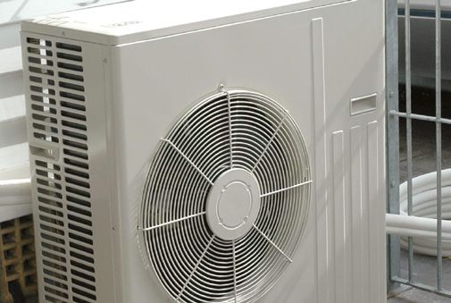
4

Good practice guide to
heat pump installation
Index of figures and tables

                  Figure 2.1    Split system heat pump                                                 8
                  Figure 2.2    Multi-split system heat pump                                           8
                  Figure 2.3    Ducted heat pump system                                                8
                  Figure 2.4    High wall-mounted unit                                                 9
                  Figure 2.5    Ceiling cassette                                                       9
                  Figure 2.6    Floor console                                                          9
                  Table 2.1     Heat pump components                                                   10
                  Figure 2.7    Schematic diagram of reverse-cycle, air-to-air, split system
                                heat pump operation (heating mode)                                     10
                  Figure 2.8    Schematic diagram of reverse-cycle, air-to-air, split system
                                heat pump operation (cooling mode)                                     11
                  Figure 2.9    Schematic diagram of heat pump operation (heating)                     11
                  Figure 2.10   Inverter operation                                                     12
                  Figure 3.1    Schematic of heat pump performance                                     13
                  Figure 3.2    Graphic representation of heat pump efficiency                         14
                  Table 3.1     Outdoor ambient temperature rating conditions                          15
                  Table 4.1     Designing a heat pump system                                           16
                  Table 4.2     Effects of incorrectly sized systems                                   16
                  Figure 4.1    Floor-mounted unit – horizontal and vertical air discharge (heating)   18
                  Figure 4.2    Ceiling-mounted unit – horizontal air discharge (heating)              18
                  Figure 4.3    Ceiling-mounted unit – vertical air discharge (heating)                18
                  Figure 4.4    Wall/high wall-mounted unit
                                – horizontal air discharge (cooling)                                   18
                  Table 4.3     External design temperatures by territorial authority
                                (local council) areas                                                  20
                  Table 4.4     Example of a heat pump performance guide chart                         21
                  Figure 4.5    Outdoor unit clearances                                                21
                  Figure 4.6    Service access                                                         22
                  Figure 4.7    Clearances required between outdoor unit and exchange
                                LPG gas bottles                                                        22
                  Figure 4.8    Locate the outdoor unit where a solid barrier can block the sound      23
                  Figure 4.9    Wall-mounted indoor unit clearances                                    23
                  Figure 4.10   Pre-install pipework before building claddings are installed           24
                  Figure 4.11   Permitted notching and drilling of timber framing allowed
                                under NZS 3604                                                         24
                  Figure 6.1    Twin-insulated and dehydrated pipe                                     26
                  Figure 6.2    Step 1: Cleaning the tube end                                          27
                  Figure 6.3    Step 2: Roughing the end surface                                       27
                  Figure 6.4    Step 3: Fitting insert when required to support pipe                   27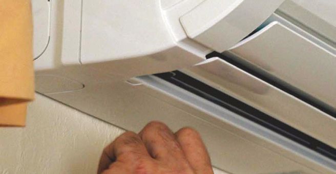
5
Index of figures and tables
Figure 6.5 Step 4: Adding ring 27
Figure 6.6 Step 5: Fitting connector marking stopline 28
Figure 6.7 Step 6: Applying sealant solution 28
Figure 6.8 Step 7: Fitting connector 28
Figure 6.9 Step 8: Compressing one connection end 28
Figure 6.10 Step 9: Completed compression connection 28
Figure 6.11 Pipe opening facing down when cutting 29
Figure 6.12 Cover pipe ends 29
Figure 6.13 Pipe bender 29
Figure 6.14 Cut pipe with tube cutters 30
Figure 6.15 Remove all burrs 30
Figure 6.16 Place the flare nut over the pipe end 30
Figure 6.17 Flare the end of the tube (A) 30
Figure 6.18 Flare the end of the tube (B) 30
Figure 6.19 Flare the end of the tube (C) 30
Figure 6.20 Flare the end of the tube (D) 31
Figure 6.21 Apply oil to the back of the flared pipe and the flare joint 31
Figure 6.22 Connect the pipes (A) 31
Figure 6.23 Connect the pipes (B) 31
Figure 6.24 Tighten connection (A) 31
Figure 6.25 Tighten connection (B) 31
Table 6.1 Fixing spacings for copper tubing 32
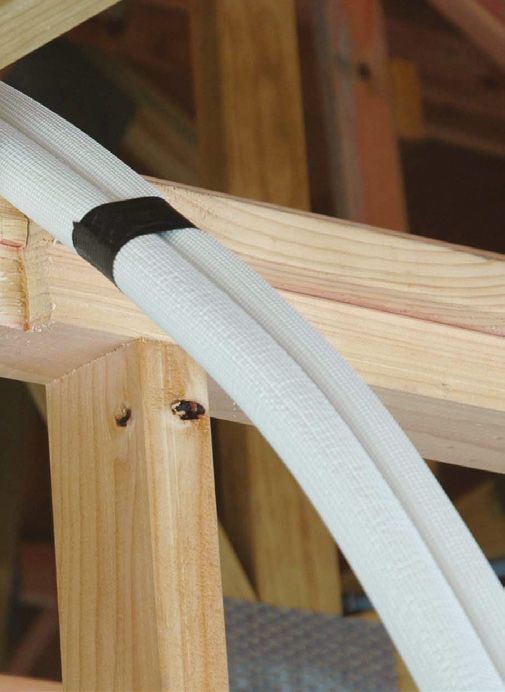
Figure 6.26 Run pipe/cable across truss chord/ceiling joist 33
Figure 6.27 Notch the top plate and studs (A) 33
Figure 6.28 Notch the top plate and studs (B) 33
Figure 6.29 Fix galvanised mild steel strap to hold pipe/cable 34
Figure 6.30 Wedge the pipe cable end into the stud 34
Figure 6.31 Braze pipe ends closed 34
Figure 6.32 Fix galvanised mild steel strap to hold pipe/connection cable 34
Figure 6.33 Feed pipe/cables through building wrap 34
Figure 6.34 Seal pipes or sleeve 34
Figure 7.1 Maximum pipe length and height 36
Figure 7.2 Screw-fix installation plate 36
Figure 7.3 Drill a hole through the wall 37
Figure 7.4 Slope of wall penetration 37
Figure 7.5 Release the tubing and drainage hose 37
Figure 7.6 Feed the connecting cable through the wall 37
6

Index of figures and tables

                  Figure 7.7    Tape tubing, drainage pipe and connecting cable together       37
                  Figure 7.8    Feed taped bundle through the hole                             37
                  Figure 7.9    Attach unit to wall bracket (A)                                38
                  Figure 7.10   Attach unit to wall bracket (B)                                38
                  Figure 7.11   Ensure unit is securely seated                                 38
                  Figure 7.12   Taped pipes, drainage pipe and connection cable through hole   38
                  Figure 7.13   Expose flared pipe ends                                        38
                  Figure 7.14   Unobstructed gap under outdoor unit fixed on concrete
                                pad cast in place                                              39
                  Figure 7.15   Concrete pad construction                                      39
                  Figure 7.16   Fixing unit to a timber deck                                   40
                  Figure 7.17   Pack with plastic shims to level                               40
                  Figure 7.18   Wall-mounted unit on brackets – masonry wall                   40
                  Figure 7.19   Bind insulation with vinyl tape                                41
                  Figure 7.20   Tape drainage hose to drainage outlet                          41
                  Figure 7.21   Install trunking neatly                                        42
                  Figure 7.22   Fit refrigerant piping, drainage pipe and connecting
                                cable into trunking                                            42
                  Figure 7.23   Fill hole around piping with sealant                           42
                  Figure 7.24   Seal around cover                                              42
                  Figure 7.25   Fit cover over opening                                         42
                  Figure 7.26   Apply oil to the back of the flare and the outdoor unit        43
                  Figure 7.27   Connect pipes and tighten flare nut                            43
                  Figure 7.28   Tighten flare nut connections                                  43
                  Figure 7.29   Remove vacuum pump and gauges (A)                              44
                  Figure 7.30   Remove vacuum pump and gauges (B)                              45
                  Figure 7.31   Remove vacuum pump and gauges (C)                              45
                  Figure 7.32   Progressively release the vacuum                               45
                  Figure 7.33   Tighten valve caps                                             45
                  Figure 9.1    Connect power supply cable to terminal block                   48
                  Figure 9.2    Install lockable isolating switch (A)                          48
                  Figure 9.3    Install lockable isolating switch (B)                          49
                  Figure 9.4    Install lockable isolating switch (C)                          49
                  Figure 9.5    Replace service cover to outdoor unit                          49
                  Figure 9.6    Example of a nameplate on an outdoor unit                      49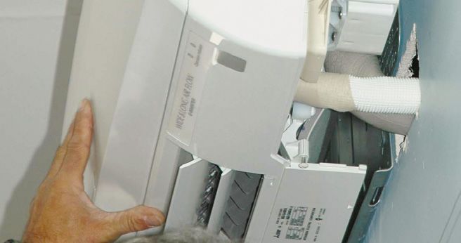
7

1.0                Introduction
                   Heat pumps have become increasingly popular in New Zealand homes over recent years,
                   as they are an energy efficient and convenient way of heating and cooling.
                   By using a relatively small amount of electricity, a heat pump can extract heat energy
                   from one location – typically outdoor air – and transfer it to another location to provide
                   heating. The reverse process can provide cooling.
                   Good design and installation are fundamental to a heat pump system’s effectiveness
                   and efficiency. It involves understanding the importance of correct sizing for the ambient
                   conditions, selecting the right unit for the local environment and correctly installing the unit.
                   This guide provides good practice guidelines for designing and installing the most
                   common type of residential heat pump system – air-to-air single-split heat pump
                   systems (also known as reverse-cycle air conditioners), used primarily for heating.
                   The guide is aimed at experienced installers of heat pumps, and it gives the process to
                   follow for system design and installation into both new and existing homes.
                   Note that this guide does not cover:
                   • multi-split or ducted heat pump systems

                   • ground-to-air, water-to-air or water heating systems

                   • DIY installations – EECA recommends heat pump systems are installed by

                     experienced installers
                   • weathertightness and airtightness of the building envelope and structural integrity

                     (though this must be maintained).

Before you begin
                   Insulate first
                   Before installing a heat pump into any home, reduce heat loss as much as possible by:
                   • adding ceiling and underfloor insulation where practicable

                   • adding weather stripping to doors and windows

                   • eliminating draughts.

                   Ensure you are qualified and prepared
                   The installation of any heat pump system should be carried out by suitably qualified
                   installers who:
                   • have the correct toolkit to allow them to carry out the work

                   • are licensed to carry out the electrical work

                   • hold an Approved Filler Compliance Certificate for the handling of refrigerants.

                   •   NOTE: New regulations are underway that will require heat pump installers to
                       have suitable qualification/ certification/ registration from 1 January 2020. Check
                       with your industry association for updates (www.irhace.org.nz).
                   Know your standards and regulations
                   Standards and regulations applicable to a heat pump installation that must be complied
                   with include the following:
                   • Building Code Clauses B1 Structure, E2 External moisture and G9 Electricity

                   • Electricity (Safety) Regulations, including the cited edition of AS/NZS 3000 Electrical

                     installations (known as the Australian/New Zealand Wiring Rules)
                   • New Zealand electrical codes of practice

                   • Health and Safety at Work Act (HSWA) 2015

                   • Australia and New Zealand Refrigerant Handling Code of Practice 2007 and standards

                   • Consumer Guarantees Act 1993, which places a legal obligation on the installer to

                     install a system that is suitable for the situation it is installed in
                   • Energy Performance – AS/NZS 3823 units must meet minimum energy performance

                     requirements and have suitable labelling provided.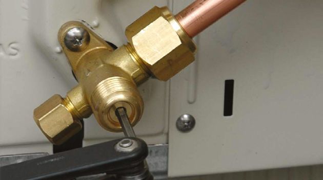
8

2.0             Heat pump systems
                This section provides a general overview of heat pump types, components and how heat
                pumps work.

2.1 Types of heat pump systems
                Air-to-air, reverse-cycle heat pump configurations are shown below.
                The most commonly installed residential heat pump in New Zealand is an air-to-air,
                single-split system. This guide covers design and installation of this type of system only.
                Single-split system – consisting of an           Figure 2.1 Split system heat pump

                outdoor unit and a single indoor unit
                connected to the coil by pipework
                containing the refrigerant (Figure 2.1).                                             indoor unit

                                                                              outdoor
                                                                                unit                 heat out

                                                                                  air in

                Multi-split system – consisting of an            Figure 2.2 Multi-split system heat pump

                outdoor unit supplying a number of
                indoor units (Figure 2.2). Not covered
                                                                                              indoor units
                by this guide.
                                                           outdoor
                                                             unit

                                                             air in                heat out                     heat out

                Ducted system – consisting of an                 Figure 2.3 Ducted heat pump system

                outdoor unit and a compressor
                                                                                              compressor
                (located outside or in the roof space)                                     duct         duct
                that is connected to a number of
                air supply outlets in selected rooms
                                                            outdoor
                or zones in the house. Zones can              unit
                                                                                   heat out                  heat out
                be controlled individually or by a
                                                             air in
                centrally located controller (Figure
                2.3). Not covered by this guide.
9

Indoor units may be:
•   high wall-mounted (Figure 2.4)          Figure 2.4 High wall-mounted unit

•   ceiling-mounted cassette (Figure 2.5)   Figure 2.5 Ceiling cassette

•   floor console (Figure 2.6)              Figure 2.6 Floor console

More information on positioning of heat pumps can be found in Section 4.0 Designing a
heat pump system.
10

2.2 Components of a heat pump
                The main components of an air-to-air heat pump and how they operate are described in
                Table 2.1 and shown in Figures 2.7, 2.8 and 2.9.
                Table 2.1 Heat pump components

                 Component                         Description
                 Evaporator                        A heat exchanger that absorbs heat from the surroundings.
                                                   •   For heating, it is the outdoor unit.
                                                   •   For cooling, it is the indoor unit.
                 Condenser                         A heat exchanger that releases heat to the surroundings.
                                                   •   For heating, it is the indoor unit.
                                                   •   For cooling, it is the outdoor unit.
                 Compressor                        Reduces the refrigerant gas volume by compressing it, causing the gas
                                                   temperature and pressure to rise, and pumps the refrigerant around the
                                                   pipework/system. The compressor operates as a variable-speed system
                                                   (see 2.4 Variable Speed (inverter) compressors).
                 Metering device                   Allows the refrigerant condensate (liquid) to expand, lowering the pressure
                                                   and temperature.
                 Coil/pipework                     Continuous, closed-circuit tubing through which refrigerant flows and heat
                                                   transfer occurs. The pipes generally have fins to increase the surface area
                                                   for the heat exchange process (see 6.0 Installing pipework).
                 Refrigerant                       The compound that circulates through the heat pump system in
                                                   both liquid and gas state, alternately absorbing and releasing heat
                                                   (see 8.0 Refrigerants).
                 Reversing valve                   Changes the direction of flow of the refrigerant to reverse the heat pump
                                                   function from heating to cooling or vice versa. Reversing the heat pump
                                                   function also occurs when the heat pump switches into defrost mode
                                                   (see 3.4 Impacts of defrost cycle on efficiency and heat output).
                 Fan                               Draws air across the evaporator coil (for heat extraction) and moves
                                                   air away from the condenser coil (for heat distribution/removal).

                Figure 2.7 Schematic diagram of reverse-cycle, air-to-air, split system heat pump operation (heating mode)

                                                       outdoor                                              indoor

                                                                         ambient air in
                                                       reversing valve
                                                                                                 gas flow
                                                       compressor

                                                                                                                             heated supply
                   evaporator                                                                                                air out

                                                                                                                             condenser

                       cool air out

                                                                                                                                    return air in

                                                                              liquid flow

                                                                               metering device
11
Figure 2.8 Schematic diagram of reverse-cycle, air-to-air, split system heat pump operation (cooling mode)
outdoor indoor
return air in
gas flow evaporator
cool supply
ambient air in air out
reversing valve
compressor
condenser
liquid flow
heated air out
metering device
Figure 2.9 Schematic diagram of heat pump operation (heating)
gas:
heat in low temperature heat in
low pressure
Evaporator
gas:
low temperature
low pressure
gas:
high temperature
Metering Device Compressor high pressure
liquid:
low temperature
high pressure
Condenser
liquid:
low temperature
high pressure
heat out heat out12
2.3 How a heat pump works
In broad terms, air-to-air heat pumps work by using electrical energy to extract energy
from the outside air and transfer it inside as heat, which makes it an efficient way of
heating. Reversing the process enables indoor heat to be removed to provide cooling.
A more detailed illustration of how a heat pump operates in heating mode can be seen
in Figure 2.9. There are five main processes in the cycle:
1. In the evaporator (outdoor unit), low-pressure, low-temperature liquid refrigerant
absorbs heat from its surroundings and evaporates, converting to a gas state and
absorbing energy as it does so (latent heat of evaporation).
2. It passes through the compressor, where the low temperature gas is reduced in
volume, resulting in a rise in both temperature and pressure.
3. As a heated and high-pressure gas, it passes through the condenser (indoor unit),
where the gas condenses (latent heat of condensation) with a release of heat into the
air surrounding the coil. A fan moves the warmed air away from the coil to distribute
it throughout the indoor space.
4. Still under pressure, the cooled refrigerant, now in liquid state, passes through the
metering device, where rapid expansion results in a reduction in pressure.
5. In the low-pressure, low-temperature state, the refrigerant flows back into the
evaporator, and the cycle is repeated.
2.4 Variable-speed (inverter) compressors
The compressor of a modern heat pump is commonly a variable-speed compressor
– also known as an inverter compressor. Heat pumps with variable speed (inverter)
compressors are more efficient than heat pumps with fixed speed compressors.
An inverter or variable-speed compressor has a number of advantages over fixed-speed
units which are no longer common.
They have a 'soft start' and run at variable speed, decreasing as the temperature
approaches set point and increasing as the temperature begins to fall. The varying
speed delivers heating or cooling as required and maintains a more constant
temperature that has smaller fluctuations (Figure 2.10). This results in improved
efficiency, reduced vibration and quieter operation.
Figure 2.10 Inverter operation
temperature range
set temperature
fluctuation
Temperature (°C)
Time13
3.0 Heat pump performance
This section covers the different factors that influence the efficiency and performance of
heat pumps.
Understanding heat pump performance is essential when it comes to selecting a heat
pump (which is covered in Section 4.0 of this guide).
Figure 3.1 Schematic of heat pump performance In theory, the total heat that could be
available for heating is the sum of the heat
extracted from the source plus the energy
required to drive the heat pump. Thus, if
1 kWh of electricity is required to drive a
heat pump and 2 kWh of energy can be
3 kW out
extracted from the heat source, the total
energy delivered could theoretically be
2 kW from air
3 kWh, giving an efficiency of 300% (Figure
3.1).
1 kW electricity
In practice, other factors influence the actual efficiency of a heat pump:
• climate
• heating and cooling demands
• source and supply temperatures
• auxiliary energy consumption (pumps, fans)
• heat pump size to meet heating/cooling demand
• operating characteristics.
3.1 Heat pump efficiency
Heat pump efficiency is the ratio of the heating or cooling delivered, compared to the
electrical energy required to operate the system.
The ratios are given in two ways:
• coefficient of performance (COP) – the ratio of heating delivered, compared to the
electrical energy input
• energy efficiency ratio (EER) – the ratio of cooling delivered, compared to the
electrical energy input.
The higher the COP or EER, the greater is the efficiency of the heating or cooling system.
You can calculate the COP by taking the heating output (in kW) and dividing it by the
electrical input (in kW).
These values can be found on the energy rating label (see Section 3.2) or manufacturer’s
information.
An acceptable level of COP should be at least 3, and better products may well have a COP
of 4 or more.
NOTE: Heat pump efficiency ratios are sometimes presented as ACOP and AEER,
which are annualised figures that includes standby power in the calculation.14
3.2 Energy rating label
The energy rating label gives information on how much energy a product uses so you
can compare models. Every heat pump sold in New Zealand must display this label. The
number of stars tells you how well the product performs – the more stars the better.
3.3 Effects of temperature on efficiency and heating capacity
Efficiency and heating capacity of a heat pump system are not constant – they vary
along with the temperature differential between indoor and outdoor air. A heat pump’s
rated efficiency and heating capacity are for particular outdoor temperatures and
heating/cooling loads. When designing a system it is important to understand how it will
perform at lower temperatures.
As the difference between outdoor temperature and desired indoor temperature
increases, the efficiency of a heat pump system decreases. This is illustrated in Figure
3.2, which shows the efficiency of a heat pump in heating mode reducing as the outdoor
temperature decreases.
Different heat pumps will perform very differently at sub-zero temperatures – some
may keep performing down to -20˚C while others will struggle at temperatures below
freezing.
Figure 3.2 Graphic representation of heat pump efficiency
Outside Air Temp (ºC)
Another temperature-related factor that affects heating efficiency is the extra energy
required for defrosting at low temperatures. At temperatures up to around +7 degrees
Celsius, any water vapour in the air may start to condense and freeze onto the
evaporator (outdoor heat exchanger) coils. This will disrupt the heat flow, and the coils
must be de-iced for heating to be able to continue (see Section 3.4 Impacts of defrost
cycle on efficiency).15
Heat pumps are rated for efficiency and capacity output under laboratory conditions at
a particular ambient outdoor temperature. However, actual mid-winter temperatures
in some parts of New Zealand, particularly in the central North Island and in the South
Island, will give significantly different performance.
For this reason, standardised testing of heat pumps can be done at three levels of
specific temperature and humidity. These are called H1, H2 and H3 and are shown in
Table 3.1.
Table 3.1 Outdoor ambient temperature rating conditions
Rating Outdoor ambient temperature (˚C) rating conditions
Dry bulb (DB)
H1 7˚C
H2 2˚C
H3 -7˚C
These ratings allow you to use a range of design temperatures to select heat pumps
for areas where the temperature may often be below 0˚C. This is important to ensure
that the heat pump will be able to provide the required heating capacity at low outdoor
temperatures relevant for the local climate of the home or building (see 4.5 Step 3:
Calculate heat load requirement).
Manufacturers will also often test their product at other temperatures (e.g. -5, 0,
5, 10˚C etc).
3.4 Impacts of defrost cycle on efficiency and heat output
For optimal heat pump efficiency and performance, you must size a system correctly
to minimise the energy losses and disruptions to heating delivery that occur during the
defrost cycle.
The defrost cycle is necessary to remove ice build-up on evaporator coils. Ice build-up
occurs from below 7˚C (especially in high humidity), when any water vapour in the air
will start to condense and freeze onto the evaporator (outdoor heat exchanger) coils.
This will disrupt the heat flow, and the coils must be de-iced for heating to be able to
continue.
To remove ice build-up on the coils, most heat pumps have a defrost cycle where the
system switches into cooling mode (taking some heat from inside the home), which
effectively cools the room slightly.
Some systems have a closed-loop cycle to use waste heat from the motor/compressor to
defrost the coils.
During defrosting, no heat is supplied to indoors.
Undersized heat pumps will need to defrost frequently in low ambient temperatures,
reducing the system’s efficiency and ability to provide sufficient heating.
The defrost cycle control is either:
• a time-temperature defrost, starting and stopping at preset times (30-, 60- or
90-minute intervals); or
• on-demand defrost, which is generally more efficient because it operates only when
it detects frost build-up on the outdoor coil by monitoring air and coil temperature,
outdoor airflow, pressure differential across the coil and refrigerant pressure.
Note: If a heat pump goes into multiple defrosts over a short time frame (1-2 hours), the
unit should be serviced. This issue could also occur where the heat pump is undersized
and struggling to heat the space.
Systems that include a dry-coil defrost cycle briefly run the outdoor fan at maximum
speed before the system starts to heat again, to remove any water that may still be
on the coil fins and would immediately refreeze. This operation can be seen by water
vapour blowing from the outdoor unit before the heating cycle resumes.16
4.0 Designing a
heat pump system
This section describes the steps for designing a heat pump system that will perform as
efficiently as possible to meet the customer’s needs.
4.1 Steps for designing a heat pump system
For a well-designed heat pump follow the four steps shown in Table 4.1. Each step is
described in detail in Sections 4.3 to 4.7.
Table 4.1 Designing a heat pump system
Step Action
1 Determine requirements (Section 4.3):
• for heating/cooling
• for the building
• for the environment (e.g. protection for system
components in coastal/geothermal regions)
• for the type of unit suited to the room.
2 Determine heating capacity (kW) requirement and external design temperature
(Sections 4.4 and 4.5).
3 Select the system/model to suit the design requirements and occupant preferences
(Section 4.6).
4 Select the locations of the indoor and outdoor units (Section 4.7).
4.2 The importance of correct heat pump sizing
Correct heat pump sizing is critical to efficiency and performance. Select a unit that can
provide the required heating capacity at the external design temperature relevant for
the location of the home or building.
If the heat pump capacity is too low, the system will use more energy than necessary
(increasing running costs), will likely need to defrost more frequently during heating
operation, and may not be able to provide sufficient heating/cooling to achieve the
indoor temperatures required for occupant comfort (Table 4.2).
The extra running costs of an undersized heat pump generally outweigh the additional
cost of installing a unit that is the next size up.
Selecting a slightly oversized heat pump provides a safety margin to ensure that heating/
cooling requirements will be met. It may also result in improved energy efficiency.
However, significant oversizing should be avoided.
Table 4.2 Effects of incorrectly sized systems
If unit is: Performance Effects
Undersized Operation may be in defrost mode too • System is not delivering heat.
often (see 3.4 Impacts of defrost cycle • System may be blowing out cold air.
on efficiency and heat output).
Operation may be at full capacity too • Increased running costs.
often. • Reduced efficiency.
• Undue wear and tear, premature failure
of equipment
Oversized Increased start-up power use. • Increased running costs.
significantly • Reduced efficiency.
Short cycling because output exceeds • Too much air movement (draught)
demand. even at low fan speed.
• Increased noise.
• Undue wear and tear.
Runs at low load too often. • Reduced efficiency.17
Where the space being heated is large, installing two smaller units or a multi-split
system may give better heat distribution within the space and better control than a
large-capacity single unit.
4.3 Step 1: Determine requirements
As a first step, gather the information that you will need to determine what the most
appropriate heat pump option is for a particular home. Use the checklists below to
determine requirements for the system.
4.3.1 Checklist of heating/cooling requirements
❏❏ What is required? For example, is it mainly heating or cooling?
❏❏ What is the region and location of the building?
❏❏ Are there specific local conditions, such as microclimates within the climatic zones,
which may influence selection?
❏❏ What are the seasonal high and low ambient temperatures?
❏❏ What type of home is the system for? For example, old, new, insulated.
❏❏ Is it for a typical single room or a large or open plan room/hallway (where more than
one unit may be required)?
❏❏ What is the owner preference for the type of indoor unit? For example, a floor-
mounted unit may be better for an older user to give more direct heat flow and allow
easier access for maintenance. A high wall-mounted or ceiling-mounted unit can
provide more effective cooling and allows occupants more flexibility with arranging
furniture in the room.
❏❏ Does the owner prefer a unit that can be controlled remotely (e.g. a Wi-Fi enabled
unit)?
4.3.2 Checklist of building conditions
❏❏ Building orientation.
❏❏ Window orientation and solar gain, particularly in summer.
❏❏ Areas of walls, ceilings, windows and floors.
❏❏ Building envelope; for example, air infiltration/heat loss around doors/windows.
❏❏ Insulation levels of walls, ceilings and floors.
❏❏ Single/double glazing.
4.3.3 Environmental requirements
Select a unit that is suitable for the environment it is being installed in.
For example, geothermal regions require the indoor and/or outdoor units, coil and
pipework to be protected against atmospheric sulphur-containing gases that will cause
corrosion of the coil.
Coastal regions also require protection against corrosion for both the outdoor cabinet
and the coils. Use a proprietary coil protectant available to installers in those areas.18
4.3.4 Type of unit suited to room
Consider the options for airflow patterns in relation to room or space layout
(Figures 4.1 – 4.4). All three types of unit can be used for heating or cooling.
Different types may suit different people based on their own personal choice.
Floor console units are primarily designed Figure 4.1 Floor-mounted unit – horizontal
and vertical air discharge (heating)
for heating, as warm air rises and cold air
falls (Figure 4.1). Consider the location of
objects such as furniture that may interfere
with airflow and cause short circuiting of the
air back to the unit, reducing efficiency and
performance.
Ceiling-mounted units blow air down or out Figure 4.2 Ceiling-mounted unit – horizontal
air discharge (heating)
from the unit to circulate the warmed air
within the room (Figures 4.2 and 4.3).
Figure 4.3 Ceiling-mounted unit – vertical
air discharge (heating)
High wall-mounted units blow hot or cool air Figure 4.4 Wall/high wall-mounted unit
– horizontal air discharge (cooling)
to mix with room air before dropping to the
level of occupants (Figure 4.4).19
4.4 Step 2: Calculate heat load requirement
Using the information from Step 1, you can now calculate the required heating capacity
for the heat pump.
For rental homes, the Residential Tenancies (Healthy Homes Standards) Regulations
2019 include minimum requirements for heaters in the main living room. From 1 July
2019, a heat pump newly installed in the main living room of a rental home should at
least have the heating capacity required by these regulations.
To determine the minimum heating capacity required by the Residential Tenancies
(Healthy Homes Standards) Regulations 2019 you can either:
• use the heating assessment tool available on the Tenancy Services website, or
• do a manual calculation in accordance with Schedule 2 of the Residential Tenancies
(Healthy Homes Standards) Regulations 2019.
Use these heater sizing methods for heat pumps installed in the living room of any
home, not just rental homes. This will ensure the heat pump can meet the requirements
if the home was to become a rental home.
These heater sizing methods are also suitable for rooms other than the main living
room, for example a secondary living room or a bedroom.
4.4.1 Heating assessment tool on Tenancy Services website
Tenancy Services is part of the Ministry of Business, Information and Employment
(MBIE). Its website provides information to residential landlords and tenants and
includes an online heating assessment tool.
The online heating assessment tool aims to help landlords determine what type
and capacity heater rental homes require in the main living room to comply with the
Residential Tenancies (Healthy Homes Standards) Regulations 2019.
Whilst these regulations only apply to rental homes, the heating assessment tool is
suitable for determining the required heating capacity for any room in both rental and
owner-occupied homes in New Zealand.
The Tenancy Services heating assessment tool is available on:
www.tenancy.govt.nz/heating-tool
4.4.2 Manual calculation of required heating capacity
You can also calculate the required heating capacity manually. For details, refer to
Schedule 2 of the Residential Tenancies (Healthy Homes Standards) Regulations 2019.
This calculation method is suitable for determining the required heating capacity for
any room in both rental and owner-occupied homes in New Zealand.
The Residential Tenancies (Healthy Homes Standards) Regulations 2019 are available
on: www.legislation.govt.nz/regulation/public/2019/0088/latest/whole.html20
4.5 Step 3: Determine external design temperature
Because the heating capacity of a heat pump reduces with outdoor temperature, a
unit must be selected that can provide the required heating capacity at the lowest
winter outdoor temperature relevant to the local climate where the heat pump is being
installed. The heat pump’s capacity at that temperature will likely be different to the
rated heating output capacity.
Table 4.3 lists external design temperatures for all territorial authority (local council)
areas of New Zealand, as provided in Schedule 2 of the Residential Tenancies (Healthy
Homes Standards) Regulations 2019.
Note that there may be some variation within each area. If the location where the heat
pump is being installed has a particularly severe climate or microclimate (for example,
a sunless or damp valley), this needs to be taken into consideration. In this case, the
design temperature may be one or two degrees lower.
Table 4.3 External design temperatures by territorial authority (local council) areas
Outdoor Outdoor
Territorial authority Territorial authority
(°C) (°C)
Ashburton District Council -5 Otorohanga District Council -3
Auckland Council 1 Palmerston North City Council -3
Buller District Council -3 Porirua City Council 0
Carterton District Council -4 Queenstown Lakes District Council -6
Central Hawke's Bay District -3 Rangitikei District Council -4
Council Rotorua Lakes Council -3
Central Otago District Council -8 Ruapehu District Council -5
Chatham Islands Council -1 Selwyn District Council -4
Christchurch City Council -4 South Taranaki District Council -1
Clutha District Council -4 South Waikato District Council -3
Dunedin City Council -4 South Wairarapa District Council -4
Far North District Council 2 Southland District Council -6
Gisborne District Council 0 Stratford District Council -2
Gore District Council -4 Tararua District Council -3
Grey District Council -2 Tasman District Council -4
Hamilton City Council -3 Taupo District Council -5
Hastings District Council -2 Tauranga City Council 0
Hauraki District Council -2 Thames-Coromandel District -1
Horowhenua District Council -3 Council
Hurunui District Council -5 Timaru District Council -5
Hutt City Council -1 Upper Hutt City Council -3
Invercargill City Council -4 Waikato District Council -2
Kaikoura District Council 1 Waimakariri District Council -4
Kaipara District Council 1 Waimate District Council -5
Kapiti Coast District Council -3 Waipa District Council -3
Kawerau District Council -2 Wairoa District Council 0
Mackenzie District Council -10 Waitaki District Council -5
Manawatu District Council -2 Waitomo District Council -3
Marlborough District Council -3 Wellington City Council 2
Masterton District Council -4 Western Bay of Plenty District -1
Matamata-Piako District Council -3 Council
Napier City Council -2 Westland District Council -2
Nelson City Council -3 Whakatane District Council -2
New Plymouth District Council 0 Whanganui District Council -1
Opotiki District Council -2 Whangarei District Council 221
4.6 Step 4: Select a system to meet requirements
You should now have all the information needed to select the right heat pump system
for the home’s needs. Things to keep in mind:
• Inverter type units are recommended in most cases for their increased efficiency.
• Consider suitability for the environment (i.e. sea spray, sulphur from geothermal
activity).
Some manufacturers provide performance guide charts for selecting a heat pump
system similar to Table 4.4. You should use products with this information available,
particularly in colder climates.
Where heating capacity data is not available for the precise external design temperature
relevant to the installation site, use the heating capacity information for the nearest
outdoor temperature available below the external design temperature.
Table 4.4: Example of a heat pump performance guide chart
Model A: Capacity 4.0 kW rated output
Indoor (°C) Outdoor (°C)
20 -10 -5 0 2 7
Output Input COP Output Input COP Output Input COP Output Input COP Output Input COP
2.4 0.77 3.12 2.88 0.91 3.15 3.7 1.1 3.31 3.8 1.12 3.4 4.1 1.18 3.5
Model B: Capacity 6.0 kW rated output
Indoor (°C) Outdoor (°C)
20 -10 -5 0 2 7
Output Input COP Output Input COP Output Input COP Output Input COP Output Input COP
3.6 1.3 2.76 4.32 1.54 2.8 5.1 1.71 2.98 5.2 1.75 3.0 6.1 1.9 3.2
Model C: Capacity 8.0 kW rated output
Indoor (°C) Outdoor (°C)
20 -10 -5 0 2 7
Output Input COP Output Input COP Output Input COP Output Input COP Output Input COP
4.8 1.85 2.59 5.65 2.05 2.75 6.2 2.25 2.8 6.4 2.4 2.7 8.1 2.6 3.1
As an example, for a required heating capacity of 5.6 kW and an external design
temperature of +1°C, by referring to the example performance guide chart in Table 4.4,
an 8 kW rated capacity heat pump should be selected as it is able to deliver 6.2 kW
output at 0°C (nearest temperature below +1°C with data available), which will meet the
heating capacity requirement. The 6 kW rated capacity heat pump model only provides
5.1 kW output at 0°C which is less than the required 5.6 kW and therefore insufficient.
4.7 Step 5: Locate the units
Correct location of both outdoor and indoor units is essential for optimum performance.
Many problems with poorly performing heat pumps are due to poor location of units.
4.7.1 Outdoor units
Locate outdoor units: Figure 4.5 Outdoor
unit clearances 600 mm
• to allow unimpeded air flow around the unit
(to avoid the creation of a microclimate
that reduces heat pump performance and
efficiency)
150 mm
• in a position that gets full sun in winter 150 mm
• in accordance with the manufacturer’s
recommendations for distances to
obstructions. If the manufacturer’s
recommendations are not given, provide 600 mm
service access
the following minimum distances from
obstructions: 500 mm
– 500 mm between air inlet and outlet faces
– 600 mm above the unit
– 150 mm to other faces (Figure 4.5).22
Locate the units: Figure 4.6 Service access
• to minimise refrigerant pipe run lengths and
bends
• to give minimum pipe runs in accordance with
the unit manufacturer’s instructions
• where condensate can easily be drained away
• to allow access for service (minimum 600 mm)
(Figure 4.6)
• where any blockage (such as from leaves or
snow) is quickly seen and can be cleared away.
Locate the units:
Figure 4.7 Clearances required between
• to be protected from the sea spray in coastal outdoor unit and exchange LPG gas bottles
areas, sheltered from frost and strong wind (strong
wind can cause the condenser fan to spin in reverse 500 mm
and burn out the motor, which is a particular problem
500 mm
when a unit is located on a roof)
• where condensation can be appropriately drained
away (see 6.1.8 Positioning and connecting the
condensate drainage pipe) condensation will
always be produced during heating and must be
able to be drained safely
• in a well ventilated area, and at a safe distance
1500 mm
from any gas sources or appliances:
– 1.5 m clearance from an exchange LPG bottle (i.e. Within space 0.5 m above
= Zone 2
gas cylinders that get swapped and refilled offsite). and 0.5 m laterally from any
cylinder valve, extending 1.5
– 3.5m clearance from an in-situ fill LPG bottle m laterally at the base of the
cylinder.
(i.e. gas cylinders that get refilled by tanker onsite)
– 0.5 m clearance from a gas water heater.
NOTE:
• DO NOT locate where noise can cause a disturbance to home occupants or to
neighbours (see Section 4.7.1.1 for more information)
• DO NOT locate under the house or a deck, or any location that may impede airflow,
only install where there is ample space and clearance
• DO NOT locate below a window where the unit has a vertical discharge
• DO NOT locate so that multiple units are competing against each other for air flow
• DO NOT locate where the air outlet is directed to where people pass, such as
across an accessway or path
• DO NOT locate the outdoor unit on a balcony or deck that is more than 1 m above
a surface below in a way that facilitates climbing over the balustrades or railings.
Any screen around the outdoor unit must not facilitate climbing and must not
include toe holes.23
4.7.1.1 Avoid noise disturbance
Locate outdoor units where noise from the unit cannot transmit to and disturb the
home occupant or adjacent properties. Do not install the outdoor unit under or close to
bedroom windows. Comply with council bylaws regarding permitted noise levels at the
property boundary.
There are several ways to reduce sound transmission:
• Locate the unit where a fence or solid barrier can block sound so that the line of sight
between source and receiver is blocked (Figure 4.8).
Figure 4.8 Locate the outdoor unit where a solid • At the same time avoid reflected sound
barrier can block the sound
transmission – consider the reverberation
solid fence/barrier to block sound
effects of lightweight materials such as
corrugated iron fencing.
• Mount the unit on isolation mounting
blocks or pads to absorb vibration.
• Ensure the owner is aware of the need
to carry out regular maintenance to
outdoor unit have worn bearings or other noisy parts
replaced.
• Refer to the manufacturer’s mounting
instructions for recommended clearances
direction of sound
to ensure airflow around the unit.
4.7.2 Indoor units
Locate indoor units:
• according to the type of unit, i.e. high wall, under-ceiling, floor-mounted
• on an external wall if possible
• to avoid directing airflow onto seating locations or electronic equipment
• to direct airflow to the coldest point in the room (but not towards a window)
• appropriately for room layout and airflow patterns
• in accordance with the manufacturer’s recommendations for minimum clearances.
Figure 4.9 Wall-mounted indoor unit clearances
Otherwise allow:
– 40-150 mm minimum above and 150
150 mm mm minimum on either side of a wall-
mounted unit
40-150 mm
– 2.0 m minimum (measured to the
bottom of the unit) above floor for a
high wall or ceiling-mounted unit
– 50 mm minimum to each side for a floor
150 mm console (Figure 4.9)
• so that a clear airflow path is maintained
2.0 m
(high wall)
• to minimise refrigerant pipe run lengths and
to underside
bends (for each 90° bend, deduct 1% from
the heat pump heating/cooling capacity)
• so that the condensate drainage pipe can
drain to outside without the need for a
condensate pump.
NOTE:
• DO NOT locate in a tight corner or space
• DO NOT locate behind a grille
• DO NOT locate so it directs air to a primary source of heat gain or loss,
such as windows
• DO NOT locate where there may be any steam
• DO NOT locate within a kitchen or near an automatic insect repellent dispenser
• DO NOT locate above or close to any heat source, including electrical appliances,
which could affect the performance or act as an ignition point.24
4.7.3 Building work
4.7.3.1 New building
Figure 4.10 Pre-install pipework before The best time to install pipework and cables in a new
building claddings are installed
building is when it is still under construction. Co-
ordinate with the other trades and plan the layout and
location of the system early in the building design stage
so that penetrations through the building envelope can
be made before the cladding is installed (Figure 4.10)
– Note that the penetration through the wall underlay
has not incorporated a sleeve and has not yet been
taped off with flexible flashing tape.
– Protect pipework and cables from being damaged by
other trades. Sleeving or plastic inserts can be used to
prevent pipes from being kinked.
Building Code acceptable solution E2/AS1 gives guidance on making penetrations
through the wall cladding and wall underlay – a copy is available for download from the
building.govt.nz website.
If you make the penetration through the wall cladding system, then you are responsible
for the weathertight performance of the penetration made. You will be liable for any
non-performance due to your work.
Any drilling, notching or cutting of load-bearing and support walls to fit pipes must
be within the limits specified by NZS 3604:2011 Timber framed buildings. Figure 4.11
outlines the maximum permitted allowances for drilling and notching a top plate may
be required.
Figure 4.11 Permitted notching and drilling of timber framing allowed under NZS 3604
Wall plates
19 mm max. depth
200 mm max. length
70 x 45 mm top or
bottom plate
25 mm max. depth
200 mm max. length
25 mm max. diameter 90 x 45 mm top or bottom plate
19 mm max. diameter
Studs
75 x 45 mm stud 90 x 45 mm stud
19 mm max. depth 25 mm max. diameter
19 mm max. depth for
max. 200 mm length or
22 mm cut for diagonal
timber bracing
25 mm max. depth for max. 200 mm
length or 35 mm for a max. of three
consecutive studs
NOTE: Notches in studs to be spaced at a min. of 600 mm apart.
4.7.3.2 Existing building
When installing units into an existing building:
• Identify the location of existing pipework, studs and cables before drilling holes
or making penetrations in the building.
• Ensure any drilling, notching or cutting of load-bearing and support walls to fit
pipes is within the limits specified by NZS 3604:2011 Timber framed buildings
(shown in Figure 4.11).25
5.0 Toolkit
Use the correct tools and equipment as per the following list.
Equipment
❏❏ Brazing equipment
❏❏ Set of standard hand tools
❏❏ Pipe benders
❏❏ De-burring tool
❏❏ Swaging set
❏❏ Flaring tools
❏❏ Wrenches
❏❏ Torque wrenches
❏❏ Pipe cutters
❏❏ Electronic scales
❏❏ Digital thermometer
❏❏ Oxygen free nitrogen gas cylinder with pressure gauge and manifold valve and
flexible clear hose
❏❏ Leak testing equipment
❏❏ Electronic leak tester
❏❏ Vacuum pump with backflow prevention device
❏❏ Manifold set
❏❏ Hose adaptors
❏❏ Auto ignition gas torch
❏❏ Digital vacuum gauge
❏❏ Refrigerant specific valve core removal tool
❏❏ Tape measure
❏❏ Charge valve
❏❏ Compression or locked-ring jointing tool
❏❏ Recovery cylinder
❏❏ Charge hose and connector
❏❏ Stud finder
❏❏ Safety glasses, gloves, ear protection, safety boots, hard hats and other PPE
Materials
❏❏ Copper pipe (hard/soft drawn, twin-insulated, dehydrated)
❏❏ Pipe protection
❏❏ Pipe insulation
❏❏ Electrical cable
❏❏ Oil for flared joints (refrigerant compatible)
❏❏ Galvanised mild steel straps 120 x 25 x 0.5mm
❏❏ Galvanised pipe brackets 65mm diameter
❏❏ Galvanised nails 30mm
❏❏ Condensate drainage pipe, either smooth, hard PVC pipe (best practice option) or
flexible, ribbed pipe
❏❏ Vinyl tape
❏❏ Electrical conduit
❏❏ Gas cylinder with refrigerant that is compatible with heat pump26
6.0 Installing pipework
Good pipework gives a safe, efficient and reliable installation necessary for the heat
pump system to perform properly. Too many joints, bends and long lengths can increase
the risk of leaks and reduce efficiency, as it requires more energy for the compressor to
pump the refrigerant around the system.
Many system failures occur due to poor workmanship of pipework installation.
To reduce the likelihood of problems:
• pipes must be clean and moisture-free
• use pipe sizes recommended by the manufacturer
• design pipelines for the shortest runs and minimum number of bends to limit internal
friction:
– floor consoles may not have a minimum pipe run and can be installed back to back
– high wall units have a minimum pipe run, typically 3.0-5.0m – check the
manufacturer’s instructions for this information
• insulate and protect all pipework with a rated UV capping
• slope pipes towards the compressor to allow any oil that gets into the pipes to drain
back to the compressor sump (some compressor oil will likely get into the pipeline in
any system, and if it remains there it will de-rate the system’s pressure and hence its
efficiency)
• install pipelines to allow for seismic, wind and thermal movement
• pipes must be rated for the refrigerant pressure being used in the system.
6.1 Pipework installation
Good-quality pipework involves the following steps:
1. Selecting suitable pipework and jointing (see Sections 6.1.1 and 6.1.2).
2. Ensuring pipework is clean (see Section 6.1.3).
3. Making bends properly (see Section 6.1.4).
4. Creating flared joints properly (see Section 6.1.5).
5. Ensuring pipework is well-supported (see Section 6.1.6).
6. Insulating refrigerant pipework (see Section 6.1.7).
7. Positioning and connecting the condensate drainage pipe properly (see Section 6.1.8).
6.1.1 Types of pipework
Figure 6.1 Twin-insulated and dehydrated pipe Copper pipework forms the closed-coil
system through which refrigerant flows.
Copper may be hard-drawn or soft-drawn.
Hard-drawn is recommended as best
practice for pipe diameters of 20 mm and
more, but soft-drawn is commonly used
because it is easier to work with.
Use UV-rated twin-insulated and
dehydrated pipe, which is easier to
install in trunking and in ceiling spaces
(Figure 6.1).27
6.1.2 Types of jointing
You can joint pipes by brazing or compression (lock-ring) jointing.
6.1.2.1 Brazed connections
Brazed joints provide the best resistance to pressure, temperature and stress vibrations,
and using this type of jointing is recommended as good practice. Pipe joints behind
the indoor unit and in wall spaces must be brazed, as brazed pipe connections reduce
the likelihood of leaks and take up less space. Carry out all brazing with oxygen-free
nitrogen (OFN) circulating through the pipework – this will avoid a build-up of carbon in
the pipe, which will cause oil sludging, filter blockage and eventual system failure.
6.1.2.2 Compression connections
Compression connections are an alternative to brazed connections and are far more
reliable than flare joint connections. Compression connections, as shown below, have
become more popular in recent years for a variety of reasons:
1. 100% leak free, unlike flare connections (provided the correct assembly procedure is
followed).
2. Clean, efficient and reliable.
3. No need for heavy brazing gear and associated flame, especially where there is a
special fire hazard.
4. Able to be installed indoors while building occupants are around.
5. Suitable for HC, HFC, HFO and CO2 refrigerants.
6. UL, TUV, and EN/ISO approved.
7. Max. 75 bar operating pressure, so suitable for high pressure refrigerants.
8. No requirement for nitrogen for brazing or purging.
9. Ability to connect differing pipe materials together.
10. Available from 6mm (1/4”) to 42mm (1 5/8”).
Figures 6.2 - 6.10 show an example of assembling a compression connection.
Figure 6.2 Step 1: Cleaning the tube end Figure 6.3 Step 2: Roughing the end surface
Figure 6.4 Step 3: Fitting insert when required to support pipe Figure 6.5 Step 4: Adding ring28 Figure 6.6 Step 5: Fitting connector marking stopline Figure 6.7 Step 6: Applying sealant solution Figure 6.8 Step 7: Fitting connector Figure 6.9 Step 8: Compressing one connection end Figure 6.10 Step 9: Completed compression connection 6.1.2.3 Flared joints Flared joints have a higher risk of the refrigerant leaking but may be required where connecting the pipe to the outdoor unit. If poorly installed, flared joints have a high risk of the refrigerant leaking. They can also be easily modified by unqualified persons. Flared joints may be suitable if installed correctly and in accordance with the manufacturer’s installation instructions. See 6.1.5 Creating flared joints for further information.
29
6.1.3 Maintaining cleanliness of pipework
Ensure that all pipework is clean and suitable for the system by:
Figure 6.11 Pipe opening facing down when cutting • olding the pipe opening facing down
H
when cutting (Figure 6.11).
• Removing metal filings from inside
pipework after cutting.
Figure 6.12 Cover pipe ends • lways keeping pipe ends covered with
A
caps, by brazing or taping (Figure 6.12)
– covering pipe ends prevents moisture,
dirt or foreign matter getting into the
pipes, particularly when pushing or
pulling through wall cavities.
NOTE: DO NOT let uncapped ends of pipe touch the ground.
6.1.4 Making bends
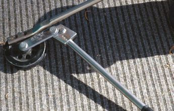
Bend all copper pipes over 9.5 mm or 3/8" diameter with the correct-sized pipe bender
(Figure 6.13) – handmade bends may kink or have a reduced internal pipe dimension,
which reduces refrigerant flow and performance.
Figure 6.13 Pipe bender When pre-insulated pipe is used:
• Split the insulation and cut away from
around the pipe.
• Bend the pipe using the correct-sized
bender.
• Replace the insulation and tape
together using vinyl tape or insert a
copper bend using brazed connections,
then insulate.30
6.1.5 Creating flared joints
Flared joints must be formed by an experienced installer, as the joints have a high risk of
the refrigerant leaking.
Flaring of joints is not a simple task and requires the correct tool for the refrigerant gas
being used and the pipe wall thickness.
Units using R410A, R32 or other high pressure refrigerants require a specific flaring tool
to cope with the refrigerant pressure and the pipe thickness.
Follow the correct steps to create a sound flared joint.
Figure 6.14 Cut pipe with tube cutters Figure 6.15 Remove all burrs
• ut pipe with tube cutters to give a cut
C • emove all burrs with a de-burr tool
R
that is straight across and clean (Figure (Figure 6.15).
6.14) – use a sharp blade and cut slightly • Remove any metal filings that may have
longer than measured length. fallen into the pipe.
DO NOT use a saw blade to cut the pipe.
Figure 6.16 Place the flare nut over the pipe end Figure 6.17 Flare the end of the tube (A)
• emember to remove the flare nut from
R • lare the end of the tube using the
F
the unit and put it over the pipe end correctly-sized flare tool and ensure
(Figure 6.16) – it is not possible to put it that the correct amount of pipe
on after flaring the pipe. protrudes (Figures 6.17 – 6.20).
Insufficient tube protrusion could lead to Excess tube protrusion could stop the
a joint that will come apart with vibration flare connection sealing properly when
and is more likely to leak. the nut is tightened.
Figure 6.18 Flare the end of the tube (B) Figure 6.19 Flare the end of the tube (C)31
Figure 6.21 Apply oil to the back of the flared pipe and the
Figure 6.20 Flare the end of the tube (D) flare joint
• pply oil to the back of the flared pipe
A
and the flare joint. Use oil compatible
with the refrigerant before connecting
pipes, i.e. use polyolester oil (POE) with
R-410A or R32 refrigerant (Figure 6.21).
Oil reduces the possibility of tearing the
flare when the nut is tightened.
Oil must not be allowed to contaminate
the refrigerant.
Figure 6.22 Connect the pipes (A) Figure 6.23 Connect the pipes (B)
• and-fasten the flare nut to connect
H
the pipes (Figures 6.22 and 6.23).
Figure 6.24 Tighten connection (A) Figure 6.25 Tighten connection (B)
• ighten the connection using two
T
spanners to the torque recommended
by the manufacturer (Figures 6.24 and
6.25) – use a torque spanner to achieve
the correct torque. Torque against the
second spanner (to secure the load
while tightening). Never tighten the
connection just against the joint.
NOTE:
• DO NOT mix polyolester oil and mineral-based oil
• DO NOT use leak lock or PTFE tape – these are not plumbing joints
• DO NOT cross thread the fittings, as you may damage them.32
6.1.6 Ensuring pipework is well-supported
Well-supported pipes help ensure the durability and performance of the system by:
• reducing the possibility of cracking or oil traps due to sagging
• eliminating vibration
• eliminating a liquid hammer effect or damage from fluid movement
• resulting in better fluid handling characteristics.
As good practice, fix copper tubing at the spacings given in Table 6.1.
Table 6.1 Fixing spacings for copper tubing
Tubing diameter (mm) Maximum fixing spacing (m)
< 6.5 1.0
6.5 – 20 1.5
25 2.0
32 – 40 2.5
> 50 3.0
Source: Australia and New Zealand Refrigerant Handling Code of Practice 2007 clause 5.18.
6.1.7 Insulating refrigerant pipework
• Insulate all refrigerant pipework to improve the efficiency of the heat pump system.
• Use a proprietary insulated pair coil, which is heat resistant up to 100oC.
6.1.8 Positioning and connecting the condensate drainage pipe
6.1.8.1 From the indoor unit
Position and connect the condensate drainage pipe from the indoor unit.
• Connect the drainage pipe to the drainage pipe outlet from the unit – if there are two
drainage outlets in the condensate tray (indoor unit), connect the drainage pipe to the
appropriate side, i.e. to suit the wall outlet location, and insert a rubber bung into the
other outlet.
• Wrap the indoor and through wall section of the drainage pipe in polyurethane foam
insulation (see 6.1.7 Insulating refrigerant pipework).
• Use smooth, hard PVC-U drainage pipe if drainage pipe runs laterally – flexible, ribbed
drainage pipe can be used for vertical drainage.
• Provide sufficient fall for condensate to drain away.
• Run the condensate hose beneath the refrigerant line when going through the wall,
to ensure a free flow of condensate.
• Connect sections of pipe with pipe solvent – where pipe sizes must be stepped down,
connect sections with silicone sealant internally, then tape around join with vinyl
tape.
• Run the indoor drainage pipe:
– to the outdoor unit and drain away to the same location as the outdoor unit
condensate
– outdoors to drain onto lawn or garden – discharge into the stormwater system is
permitted in some areas (do not discharge into a gully trap).
• Where pipe traps are recommended by the manufacturer to reduce negative pressure,
install in accordance with the manufacturer’s specifications.
• Do not allow the condensate outlet pipe to be immersed in water, as this can cause an
air lock and prevent water drainage under gravity.
• Use mechanical connectors (jubilee clips) to connect the hoses
• Locate indoor units suitably to avoid the need for a condensate pump. Where
unavoidable, install a condensate pump in accordance with the manufacturer’s
specification. Advise the owner of the maintenance requirements of the pump and
that it may make noise. Failure to do so will void any claim for water damage.You can also read