(CBTC) Communications Based Train Control - RDSO
←
→
Page content transcription
If your browser does not render page correctly, please read the page content below
GOVERNMENT OF INDIA
MINISTRY OF RAILWAYS
An Introductory Handbook on
Communications Based Train Control
(CBTC)
End Users: Indian Railways Signal Engineers
CAMTECH/S/PROJ/2020-21/SP9/1.0
February 2021
INDIAN RAILWAYS
Centre for Advanced Maintenance Technology
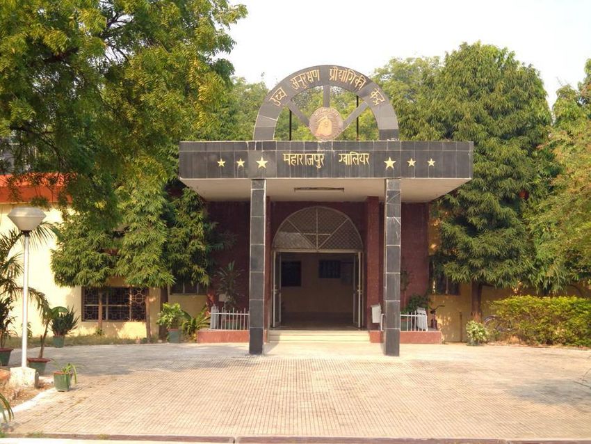
Maharajpur, Gwalior (M.P.) Pin Code – 474 005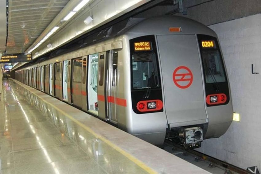
i

This page has been left blank intentionally
ii

    Introductory Handbook on
Communications Based Train Control
             (CBTC)
    CAMTECH/S/PROJ/2020-21/SP9/1.0
          February 2021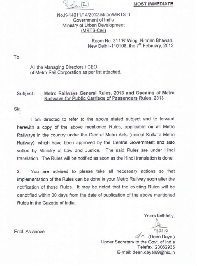
iii

This page has been left blank intentionally
iv

Foreword

Conventional railway signalling is based on colour light signals and train
detection with the help of track circuits and axle counters. Although this
technology is suitable for detection and control of trains it is still not able to
utilize the section capacity to its full advantage. Over the last decade, railways
have seen a huge transition from conventional railway signalling systems to
modern signalling systems. As there are continuous improvements in
technology, we need to keep pace with the latest trends and keep ourselves
updated.

Communications-Based Train Control (CBTC) is a modern communication-
based system that uses radio communication to transfer timely and accurate
train control information. CBTC is the choice of mass-transit railway operators
today, with over a hundred systems currently installed worldwide. In India also,
the CBTC technology is finding applications in Metro railways.

CAMTECH        has   issued   this   introductory   handbook     for   Signal    &
Telecommunication engineers to get them acquainted with the technology used
in CBTC and help them in implementing the system suitable for Indian
Railways. As this is a new technology, the information given in this handbook
is generic, which will be subsequently revised after gaining further experience.

I hope that this handbook will be helpful to S&T engineers of Indian Railways
at least in understanding the concept of CBTC. I wish them all the success.

CAMTECH Gwalior                                    Jitendra Singh
Date:                                       Principal Executive Director
v

This page has been left blank intentionally
vi

Preface
Trains are mostly worked on Absolute Block system or Automatic Block
system over Indian Railways which have fixed length blocks. These systems
maintain unutilized space between two trains running in the same direction. To
utilize the track to its maximum capacity, modern communication based
systems are used in some countries. CBTC is one such modern, radio
communication-based signalling system which enables high resolution and real-
time train control information, which increases the line capacity by safely
reducing the distance (headway) between trains travelling on the same line, and
minimizes the numbers of trackside equipment. CBTC is being introduced on
Metro Railways in India. Each Metro is using different communication
technology such as LTE, GSM-R, TETRA etc. with different detection devices
and interlocking as standby, hence their method of operation may vary slightly
from one system to another.

CAMTECH has prepared this handbook to help S&T engineers in
understanding the concept of CBTC. A case study of Kolkata Metro is also
added to get a better idea of the subject.

We are sincerely thankful to Metro Railway, Kolkata and M/s Efftronics System
Pvt. Ltd., Vijayawada, who helped us in preparing this handbook. Since
technological up-gradation and learning is a continuous process, you may feel
the need for some addition/modification in this handbook. If so, please give
your comments on email address dirsntcamtech@gmail.com or write to us at
Indian Railways Centre for Advanced Maintenance Technology, In front of
Adityaz Hotel, Airport Road, Near DD Nagar, Maharajpur, Gwalior (M.P.)
474005.
CAMTECH Gwalior                                      Dinesh Kumar Kalame
Date:                                                   Director (S&T)
vii

This page has been left blank intentionally
viii

Table of Contents
Foreword................................................................................................................................................ iv
Preface ................................................................................................................................................... vi
Table of Contents ................................................................................................................................. viii
Issue of correction slips .......................................................................................................................... x
Disclaimer............................................................................................................................................... xi
Our Objective ........................................................................................................................................ xii
CAMTECH Publications......................................................................................................................... xiii
Abbreviations ........................................................................................................................................xiv
List of Figures ........................................................................................................................................xvi
List of Tables ........................................................................................................................................xvii
Terms & Definitions ............................................................................................................................ xviii
Chapter I ................................................................................................................................................. 1
Control over movement of trains ............................................................................................................ 1
   1.1        Introduction .............................................................................................................................. 1
   1.2       Conventional methods of train control...................................................................................... 1
       1.2.1 Absolute Block System .......................................................................................................... 2
       1.2.2 Intermediate Block Signalling (IBS) System ........................................................................ 2
       1.2.3 Automatic Block Signalling (ABS) System .......................................................................... 3
       1.2.4 Cab Signalling ....................................................................................................................... 6
       1.2.5 Centralized Traffic Control (CTC) System ............................................................................ 7
   1.3       Need for a train control system utilizing maximum track space ............................................... 7
Chapter II ................................................................................................................................................ 9
Communications Based Train Control (CBTC)-A moving Block Signalling concept ........................... 9
   2.1       Introduction ............................................................................................................................... 9
   2.2       CBTC System Design ............................................................................................................. 11
   2.3       Control of train movement through CBTC ............................................................................. 14
       2.3.1 Moving Block Principle ...................................................................................................... 14
       2.3.2 Determination of train location in CBTC............................................................................ 16
       2.3.3 Communication arrangements in CBTC ............................................................................. 16
   2.4        Train Operating Modes .......................................................................................................... 23
   2.5       Performance requirements of CBTC as per IEEE 1474.1....................................................... 25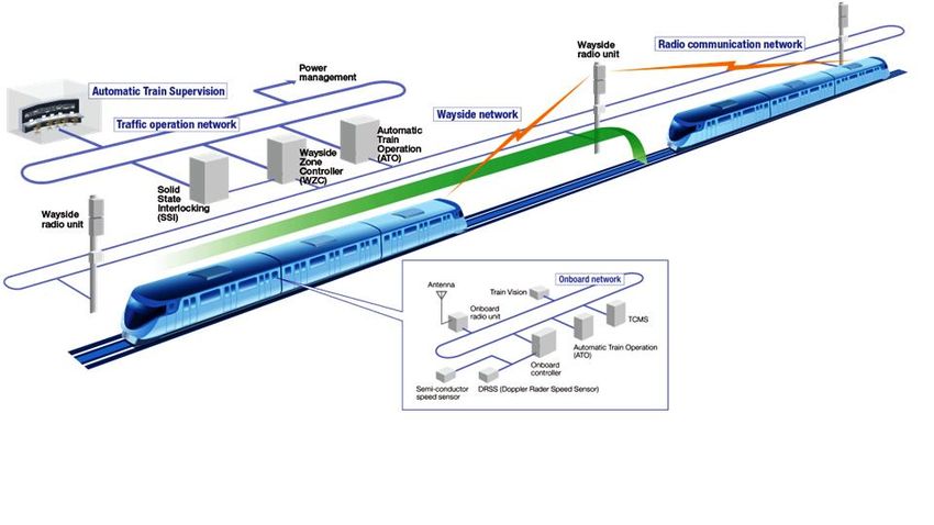
ix
2.6 Functional Requirements of CBTC as per IEEE 1474.1......................................................... 27
2.6.1 ATP functions ...................................................................................................................... 27
2.6.2 ATO functions .................................................................................................................... 31
2.6.3 ATS functions ...................................................................................................................... 31
2.7 User Interface Requirements of CBTC as per IEEE 1474.2 ................................................... 33
2.7.1 Operations related user interface requirements –train-borne subsystems ............................ 33
2.7.2 Train-borne subsystems –inputs........................................................................................... 34
2.7.3 Operations related user interface requirements – non-train-borne subsystems .................... 36
2.7.4 Maintenance-related user interface requirements ............................................................... 36
Chapter III ............................................................................................................................................. 38
Applications of CBTC in Mass Transit................................................................................................. 38
3.1 Metro trains using CBTC technology ..................................................................................... 38
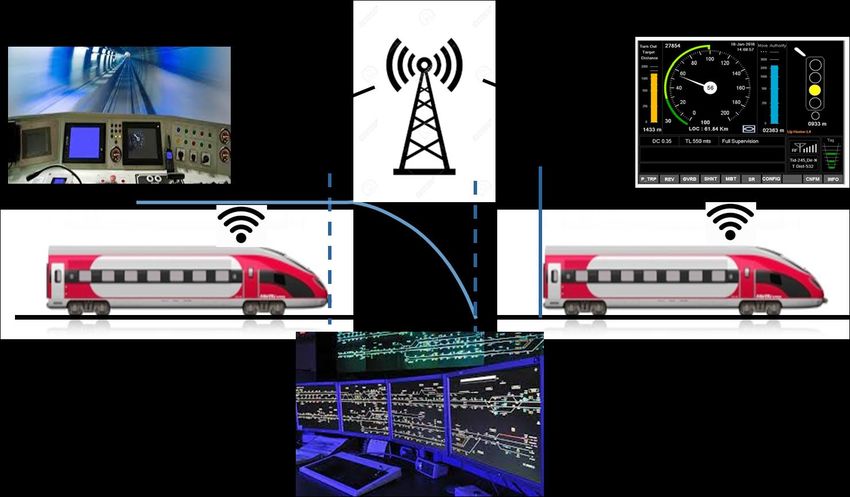
3.2 Metros with CBTC in India .................................................................................................... 39
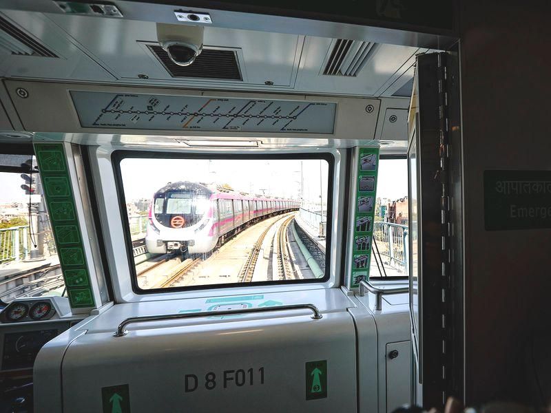
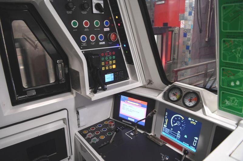
3.3 India's first driverless train on Delhi Metro - A new beginning ............................................. 41
3.4 Comparison between parameters of Mainline Railway and Metro Railway ........................... 43
Chapter IV............................................................................................................................................. 44
Kolkata East-West Metro Line 2 with CBTC Technology – A case study........................................... 44
4.1 Introduction .............................................................................................................................. 44
4.2 Functioning of CBTC .............................................................................................................. 45
4.3 Signalling assets ....................................................................................................................... 46
4.4 Telecom Assets ...................................................................................................................... 51
4.5 List of Signalling Assets at E-W Metro Corridor ................................................................... 53
4.6 List of Telecom Assets at E-W Metro Corridor ........................................................................ 55
4.7 Building Requirements ............................................................................................................... 57
Annexure ............................................................................................................................................... 58
Metro Railways General Rules 2013 .................................................................................................... 58
& ........................................................................................................................................................... 58
Opening of Metro Railways for Public Carriage of Passengers Rules ................................................. 58
2013 ...................................................................................................................................................... 58
References ............................................................................................................................................ 64x
Issue of correction slips
The correction slips to be issued in future for this report will be numbered as follows:
CAMTECH/S/PROJ/2020-21/SP9/1.0# XX date .......
Where “XX” is the serial number of the concerned correction slip (starting from 01
onwards).
CORRECTION SLIPS ISSUED
Sr. No. of Date of issue Page no. and Item Remarks
Correction No. modified
Slipxi Disclaimer It is clarified that the information given in this handbook does not supersede any existing provisions laid down in the Signal Engineering Manual, Railway Board and RDSO publications. This document is not statuary and instructions given are for the purpose of guidance only. If at any point contradiction is observed, then Signal Engineering Manual, Telecom Engineering Manual Railway Board/RDSO guidelines may be referred or prevalent Zonal Railways instructions may be followed.
xii

Our Objective

 To upgrade Maintenance Technologies and Methodologies and achieve
 improvement in Productivity and Performance of all Railway assets and
 manpower which inter-alia would cover Reliability, Availability and
 Utilisation.

 If you have any suggestion & any specific comments, please write to us:
 Contact person : Director (Signal & Telecommunication)
 Postal Address : Centre for Advanced Maintenance Technology,
 Maharajpur, Gwalior (M.P.) Pin Code – 474 005
 Phone                : 0751 - 2470185
 Fax                  : 0751 – 2470841
 Email                : dirsntcamtech@gmail.com
xiii

CAMTECH Publications

CAMTECH is continuing its efforts in the documentation and up-gradation of information on
maintenance practices of Signalling & Telecom assets. Over the years a large number of
publications on Signalling & Telecom subjects have been prepared in the form of handbooks,
pocket books, pamphlets and video films. These publications have been uploaded on the
internet as well as railnet.
For downloading these publications
On Internet:
Visit www.rdso.indianrailways.gov.in
Go to Directorates → CAMTECH Gwalior → Other Important links → Publications for
download - S&T Engineering
or click on link
 https://rdso.indianrailways.gov.in/view_section.jsp?lang=0&id=0,2,17,6313,6321,6326

On Railnet:
Visit RDSO website at 10.100.2.19
Go to Directorates → CAMTECH → Publications → S&T Engineering
Or click on the link
http://10.100.2.19/camtech/Publications/CAMTECH%20Publications%20Online/SntPub.htm

A limited number of publications in hard copy are also available in CAMTECH library which
can be got issued by deputing staff with official letter from controllong officer. The letter
should be addressed to Director (S&T), CAMTECH, Gwalior.
For any further information regarding publications please contact:
Director (S&T) – 0751-2470185 (O)(BSNL)
SSE/Signal - 7024141046 (CUG)
Or
Email at dirsntcamtech@gmail.com
Or
FAX to 0751-2470841 (BSNL)
Or
Write at
Director (S&T)
Indian Railways Centre for Advanced Maintenance Technology,
In front of Hotel Adityaz, Airport Road, Maharajpur,
Gwalior (M.P.) 474005
xiv

Abbreviations

   Abbreviation   Description
   ABS            Automatic Block Signalling
   ACS            Access Control System
   ATC            Automatic Train Control
   ATO            Automatic Train Operation
   ATP            Automatic Train Protection
   ATS            Automatic Train Supervision
   BBRS           Backbone Routers
   BCC            Backup Control Centre
   BO             Block Overlap
   BTM            Balise Transmission Module
   BTS            Base Tranceiver Station
   CBTC           Communications Based Train Control
   CC             Carborne Controller
   CCTV           Closed Circuit Television
   CBI            Computer based Interlocking
   CSS            Customer Switching System
   CTC            Centralized Traffic Control
   DCS            Data Communication System
   DMRC           Delhi Metro Rail Corporation
   DSLD           Double Sided Low Density
   DTO            Driverless Train Operation
   FSS            First Stop Signal
   FOTS           Fibre Optics Transmission System
   GE             Gigabit Eathernet
   GHZ            Giga Hertz
   GoA            Grade of Operation
   GPS            Global Positioning System
   IBS            Intermediate Block Signalling
   IEEE           Institute of Electrical & Electronics Engineers
   KMRCL          Kolkata Metro Rail Corporation
   LCD            Liquid Crystal Display
   LMA            Limit of Movement Authority
   LSS            Last Stop Signal
   LTE            Long Term Evolution
   MA             Movement Authority
   MCS            Monitor & Control Software
   MMI            Man Machine Interface
   MSO            Multiple System Operators
   NMS            Network Management System
   OBCU           On Board Controller Unit
   PAS            Public Address System
   PIDS           Passenger Information Display System
   OCC            Operations Control Centre
xv

PD      Primary Digital
PSD     Platform Screen Door
PSTN    Public Switched Telephone Network
PSR     Permanent Speed Restriction
PSC     Central Control Panel
RCS     Radio Communication System
RPM     Revolutions per minute
TOD     Train Overview Display or Train Operator’s Display
TU      Train Unit
RS      Rolling Stock
SCR     Signal Control Room
SPAD    Signal Passed at Danger
SSLD    Single Sided Low Density
SSP     Static Speed Profile
STM     Synchronous Transport Module
STO     Semi-Automatic Train Operation
TETRA   Terrestrial Trunk Radio
TFTD    Thin Film Transistor Display
TMS     Train Management System
TRS     Tag Reader System
TSR     Temporary Speed Restriction
UPS     Uninterrupted Power Supply
UTO     Unattended Train Operation
VOBC    Vehicle On Board Controller
Wi-Fi   Wireless Fidelity
ZC      Zone Controller
xvi

List of Figures
Figure 1: Absolute Block System ............................................................................................................. 2
Figure 2: Intermediate Block Signalling (IBS) System .............................................................................. 3
Figure 3: Automatic Block Signalling (ABS) System ................................................................................ 3
Figure 4: Safety distance or applying Emergency brakes in ABS system ................................................ 4
Figure 5: Artificial separation in ABS System .......................................................................................... 5
Figure 6: Multiple speed profiles in CAB Signalling ................................................................................. 6
Figure 7: Unutilized space in CAB Signalling ........................................................................................... 7
Figure 8 : Static Speed Profile of a train .................................................................................................. 8
Figure 9 : Dynamic Speed Profile of a train ............................................................................................. 8
Figure 10: Block diagram of CBTC System Design ................................................................................. 12
Figure 11:Tag connected to track for location determination .............................................................. 12
Figure 12: Wayside Zonal Controller ..................................................................................................... 12
Figure 13: Car borne CBTC Equipment .................................................................................................. 13
Figure 14 : Accelerator .......................................................................................................................... 13
Figure 15 : Tachometer ......................................................................................................................... 13
Figure 16 : Service braking curves for trains with different speeds ...................................................... 14
Figure 17 : Fix Block working................................................................................................................. 15
Figure 18 : Moving Block working ......................................................................................................... 15
Figure 19 : Train location determination through Transponder Tags or Beacons ................................ 16
Figure 20 : Basic structure of communication in CBTC ......................................................................... 17
Figure 21 : Onboard components of CBTC ............................................................................................ 18
Figure 22 :Wayside components of CBTC.............................................................................................. 19
Figure 23 : A Typical CBTC communication arrangement ..................................................................... 21
Figure 24 : A typical plan showing train borne and wayside subsystems of CBTC installation ............ 22
Figure 25 : Graph showing ATP profile for a train ................................................................................ 29
Figure 26:Target Speed & Target Distance shown on TOD Departure Permitted with Train & Platform
Doors Closed.......................................................................................................................................... 35
Figure 27 :Details of Analog circular display of TOD ............................................................................. 35
Figure 28 :TOD–Train operators Display -Train Stopped at a Station. No Departure Permitted with
Train & Platform Doors Open................................................................................................................ 35
Figure 29: Red Line Train of Delhi Metro .............................................................................................. 40
Figure 30 :View from inside of Driverless Delhi Metro cab ................................................................... 41
Figure 31 : Inside view of Driverless Delhi Metro cab ........................................................................... 41
Figure 32 : Kolkata East-West Metro Line 2 Route Map ....................................................................... 44
Figure 33 :CBTC System Architecture .................................................................................................... 48
Figure 34: ZC Cabinet Front view .......................................................................................................... 49
Figure 35: Train Operator Display (TOD)............................................................................................... 50
Figure 36: Operations menu for ATS operations ................................................................................... 50
Figure 37: Schedule Menu Bar for ATS operations................................................................................ 51
Figure 38 : DCS as a medium for CBTC & BBRS ..................................................................................... 52
xvii

List of Tables

Table 1: Levels of Automation                                 23
Table 2 : Typical parameters of CBTC                          26
Table 3 : Particulars of some Metros using CBTC technology    38
Table 4 : List of Metros in India using CBTC Technology       39
Table 5 : Delhi Metro lines and routes                        39
Table 6 : Comparative of Main line and Metro Railways         43
xviii
Terms & Definitions
1. Accelerator
The control used by the driver of a locomotive to regulate the speed is sometimes called
the accelerator.
2. Automatic Train Protection (ATP)
Automatic Train Protection (ATP) is a type of train protection system which continually
checks that the speed of a train is compatible with the permitted speed allowed by signalling,
including automatic stop at certain signal aspects. If it is not, ATP activates an emergency
brake to stop the train. In other words it provides Fail safe protection against over speed,
collision & other hazardous conditions through train detection, train separation &
interlocking. The main functions of ATP are:
Detection and Prevention of SPAD
Display of signal aspect, movement authority, target distance and speed.
Continuous train control.
Protection for Permanent and temporary speed restriction.
3. Automatic Train Operation (ATO)
Automatic train operation (ATO) is an operational safety enhancement device used to
help automate the operation of trains. The degree of automation is indicated by the Grade of
Automation (GoA), up to GoA level 4 (where the train is automatically controlled without
any staff on board). On most systems, there is a driver present to mitigate risks associated
with failures or emergencies. The primary functions performed by ATO are:
Automatic speed regulation
Automatic station stopping
Train and platform door control
4. Automatic Train Supervision (ATS)
Automatic Train Supervision (ATS) is responsible for monitoring and controlling the train
system to ensure that it conforms to an intended schedule and traffic pattern in order to
optimize railway operations and service reliability. ATS helps to avoid or reduce damage
resulting from system abnormalities and equipment malfunctions by performing the
following tasks:
Supervision of train status,
Automatic routing selection,
Adjustment of train operations during failures/unusual incidents
Automatic schedule creation,
Automatic operations logging,
Statistics and report generation,
Automatic system status monitoring,
Coordination of personnel scheduling for train management.
5. Automatic Train Control (ATC)
The ATC system ensures the following key safety functions; safe train separation, prevention
of over-speed derailments, fail safe train detection, broken rail detection, interlocking rules
enforcement, hazard response and work zone protection. The overall ATC system is the
Table of Contentsxix
combination of Automatic Train Protection (ATP), Automatic Train Operation (ATO), and
Automatic Train Supervision (ATS).
6. Cab signalling
Cab Signalling is a railway safety system that communicates track status and condition
information to the cab, crew compartment or driver's compartment of
a locomotive, railcar or multiple unit. The information is continually updated giving an easy
to read display to the train driver or engine driver.
7. Data communication equipment
It communicates data, commands, indications and alarms between ATC subsystems and
locations. This consists of connected networks of wireless, fiber optic, and hardwired
electronic equipment.
8. Direction of movement of loco
This is the direction of the train as per Loco cab control e.g. Forward or Reverse or Neutral.
9. Dynamic speed profile
The speed-distance curve which a train shall follow without violating the static train speed
profile till the end of movement authority. This curve depends on the braking characteristics
of the train and the train length.
10. Dwell time
In transportation, dwell time or terminal dwell time refers to the time a vehicle such as a
public transit bus or train spends at a scheduled stop without moving. Dwell time is one
common measure of efficiency in public transport, with shorter dwell times being universally
desirable.
11. Emergency brake
It is fail-safe, open-loop braking to a complete stop, maximum stopping distance is assured,
brake is irreversible. It involes shutting off power and full application of brakes without any
loss of time.
12. Driverless Train Operation, DTO
In Driverless Train operation (DTO) Starting and stopping are automated, but train attendant
operates the doors and drives the train in case of emergencies.
13. Emergency braking distance
Emergency braking distance is the distance travelled by train before coming to a stop by sudden
application of brake at one stretch.
15. Grade of Automation (GoA)
The list of automated train systems is ordered in descending order of the degree of
automation. It uses the Grade of Automation (GoA) classifications specified by the standard
IEC 62290‐1. This list focuses heavily on trains in the classical sense used for large-scale
railways for passengers and freight :
Table of Contentsxx
Grade of
Train operation Description
automation
GoA 0 On-sight Similar to a tram running in street traffic
A train driver controls starting and stopping, operation of
GoA 1 Manual
doors and handling of emergencies or sudden diversions.
Starting and stopping are automated, but a driver operates
Semi-automatic
GoA 2 the doors, drives the train if needed and handles
(STO)
emergencies. Many ATO systems are GoA 2.
Starting and stopping are automated, but a train attendant
GoA 3 Driverless (DTO) operates the doors and drives the train in case of
emergencies.
Starting and stopping, operation of doors and handling of
Unattended train
GoA 4 emergencies are all fully automated without any on-train
operation (UTO)
staff. All stations must have platform screen doors.
16. Headway
Headway is the distance between vehicles in a transit system measured in time or space.. The
precise definition varies depending on the application, but it is most commonly measured as
the distance from the tip (front end) of one vehicle to the tip of the next one behind it. A
"shorter" headway signifies closer spacing between the vehicles.
17. Mass Transit System
Mass transit system refers to public shared transportation, such as trains, buses, ferries etc
that can commute a larger number of passengers from origin to destination on a no-reserved
basis and in lesser time. It can also be termed as Public Transport.
18. Movement Authority
The distance upto which the train is permitted to travel without danger.
19. Moving Block Signalling
In railway signalling, a moving block is a signalling block system where the blocks are
defined in real time by computers as safe zones around each train. This requires both
knowledge of the exact location and speed of all trains at any given time, and continual
communication between the central signalling system and the train's cab signalling system.
Moving block allows trains to run closer together, while maintaining required safety margins,
thereby increasing the line's overall capacity.
20. On-board Equipment
This subsystem consists of a combination of vital and non-vital equipment located on the
passenger train-sets and maintenance vehicles. Vital equipment is used to fulfil the ATP
functions; non vital equipment is used to fulfil all non ATP functions such as ATO and
displays. The equipment includes processors, firmware, software and electronics, operator
displays, operator panel, data radios and antennas, transponder/balise antennas, code pick-up
antennas, network components, GPS receiver and antennas, tachometers and other sensors.
21. Permanent Speed Restriction (PSR)
For various reasons, although mainly because of track geometry (curvature, etc.), it is
necessary to limit the speed at which trains may travel over certain sections of the railway.
Table of Contentsxxi
These places are subject to what are termed 'permanent speed restrictions' (PSRs). In some
instances, different speeds are specified for specific types of trains.
22. Semi-automatic Operation Mode (STO)
In STO mode, Starting and stopping are automated, but a driver operates the doors, drives the
train if needed and handles emergencies.
23. Service brake
Service brake is a non-emergency brake application–which is reversible. It involves only the
shutting off the power and the gradual application of brakes.
24. Service braking distance
It is the distance required to stop the train running at the maximum permissible speed of the
line, at such a rate of deceleration that the passengers do not suffer discomfort or alarm.
25. SPAD
SPAD stands for 'Signal Passed at Danger' and occurs when a train passes a signal in the 'on'
(Red) position without authority.
26. Static speed profile
The Static Speed Profile (SSP) is a description of the fixed speed restrictions at a resolution
of 5 Kmph for a part of track sent from trackside to train.
27. Tachometer
A tachometer is an instrument measuring the rotation speed of a shaft or disk, as in a motor
or other machine. The device usually displays the revolutions per minute (RPM) on a
calibrated analogue dial or digital display.
28. Temporary Speed Restriction (TSR)
The object of a TSR is to reduce the speed of Rail Traffic to ensure safe passage over a
Section of Track when the Track is not safe for Normal Speed. A TSR is applied by a
Maintenance Representative of concerned department such as Engg. or S&T. A TSR
overrides any existing higher speed.
29. Transponder Tags or Beacons
Transponder tags or beacons are the devices installed along the track to provide coarse
position of the vehicle in a section.
22. UTO mode
In Unattended train operation (UTO) mode, the starting and stopping, operation of doors and
handling of emergencies are all fully automated without any on-train staff. Train movement is
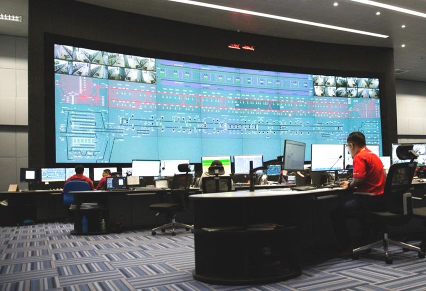
regulated by the Operations Control Centres (OCC) and not by manual train operators.
23. Wayside Equipment
This equipment consists of mainly vital equipment located in housings/location box/Relay
huts along the right of way (track) including station equipment rooms, train control
equipment houses, and signal equipment cases and cabinets.
Table of ContentsCAMTECH/S/PROJ/2020-21/SP9/1.0 1
Chapter I
Control over movement of trains
1.1 Introduction
There are broadly two types of controls which were conceptualized:
(i) Time interval method
In this method the trains running in the same direction will be dispatched at a fixed time
interval in succession. The spacing should be such that if a train stops, then, the following
train driver can stop short of the preceding train. Thus by having a time interval between
trains, a certain amount of control can be achieved. But it is not practicable due to following
drawbacks:
(a) Different types of trains like, Express/Mail, passenger, high-speed freight and low speed
freight shunting trains are running etc.
(b) The speed of all the trains are not same
(c) The terrain of the country is not same everywhere
(d) The brake power, hauling capacity, load of train is not same for all trains; and
(e) The stopping places of all trains are not the same.
Hence, it is not possible to control the movement of trains under the "Time interval
method". A better method of control is called the "Space Interval Method" is adopted.
(ii) Space interval method
In this method the length of track is divided into sections called "Blocks". The entry of a train
into the ‘block’ is controlled in such a way that only when it is free, a train can be allowed to
enter it. This means that between two consecutive trains, there is a definite space interval. To
control the entry of train into the space interval or block a track side "Signal" is required. The
signals are provided at entry and exit points of the block. So, with the two controlling points
and intercommunication, it is possible to control the entry of a train into a block only when it
is vacant.
1.2 Conventional methods of train control
Under space interval method, for safe running of trains, different methods are adopted to
control the train movement between two given points, say between two stations, mainly to
ensure that no more than one train is permitted in to the block section at a time. There are
following systems of train working which are mainly adopted over Indian Railways:
Communications Based Train Control February 2021CAMTECH/S/PROJ/2020-21/SP9/1.0 2
1.2.1 Absolute Block System
This is the most widely used system on Indian Railways.
The space between two stations is termed as block section. (typically 6 km or more)
Entry into the block section is controlled through human agencies in the form of station
masters at two stations.
Train is allowed to leave a station only when block section is free of any train and line
clear is obtained from station in advance.
Conditions for line clear are:
(i). On double line, the line must be clear upto First Stop Signal (FSS) plus an adequate
distance known as Block Overlap (BO).
(ii). On single line, the line must be clear of trains running in the same direction upto First
Stop Signal (FSS) plus an adequate distance or Block Overlap (BO), and is clear of
trains running in opposite direction.
If we assume the system of working to be multiple aspect colour light signalling, the
adequate distance or Block Overlap (BO) is taken as 180 metres.
Figure 1: Absolute Block System
Limitations of Absolute Block System
Although there is space for more trains in the block section, only one train can be dealt in
each direction at a time
.
Where the Absolute Block Section is long (say 12 -14 km) and frequency of trains is more, a
system known as Intermediate Block Signalling (IBS) system is provided.
1.2.2 Intermediate Block Signalling (IBS) System
IBS is an arrangement made on a Double Line Section for increasing the Section Capacity by
splitting of a long Block Section into two Sections namely ‘Rear Section’ and ‘Advance
Section’ by installing an IB Signal at the point of bifurcation of that running Line with
respect to the nominated direction of traffic.
Table of Contents
Communications Based Train Control February 2021CAMTECH/S/PROJ/2020-21/SP9/1.0 3
Figure 2: Intermediate Block Signalling (IBS) System
Limitations of IBS system
Maximum two Trains can be dealt on a lengthy Double Line Block section on each
nominated running line by adopting IBS system.
A more better system in which more than two trains can be dealt is called Automatic Block
System.
1.2.3 Automatic Block Signalling (ABS) System
In this system the line between two stations is provided with Continuous Track Circuits
or Axle Counters.
The line between two stations is divided into a series of sections known as "Automatic
Block Signalling Section".
The length of these Automatic Block Signalling sections is normally equal to the braking
distance as per the maximum speed permitted in the section.
Entry into each automatic block signalling section is protected by a colour light Multiple
Aspect Stop Signal.
Figure 3: Automatic Block Signalling (ABS) System
Communications Based Train Control February 2021CAMTECH/S/PROJ/2020-21/SP9/1.0 4
Above Figure 3 illustrates the working of Automatic Block System.
Track Circuits or Axle Counters should control the aspects of the Signal such that:
It cannot display the `OFF' aspect unless the line is clear not only upto the next stop
signal but also for an adequate distance beyond it. The adequate distance referred above
is termed as overlap and shall not be less than 120 meters.
For Signal 1 to assume Yellow - line must be clear for one block and one overlap.
For Signal 1 to assume Green- line must be clear for two blocks and one overlap.
In other words, minimum one block and overlap must be clear for allowing a train into the
block section.
Limitations of ABS System
Although in Automatic Block Signalling System there is better utilization of section capacity
as compared to the earlier two systems as more trains can be dealt, but full capacity
utilization is still not done as shown in the following Figures.
Figure 4: Safety distance or applying Emergency brakes in ABS system
From the above Fig.No.4 it can be seen that, with Train B occupying Block 3, if Train A
passes Signal No.2 at danger travelling at 100 Kmph and if it requires 1 Km to stop by
applying emergency brakes, the block separating Train A from Train B must be at least 1 Km
long to satisfy the safety requirement.
Communications Based Train Control February 2021CAMTECH/S/PROJ/2020-21/SP9/1.0 5
Figure 5: Artificial separation in ABS System
Assuming each block section of 1 Km length, From Fig. above it can be seen that as Train B
clears overlap distance beyond Signal 3, Train A will be granted a permissive aspect of
Signal No.2. But even if Train B moves further towards Signal No. 4, Train A cannot be
granted permissive aspect of Signal No.3 until Train B clears overlap distance beyond Signal
No. 4.
Instead, an artificial separation is created between Train A and B, even though Train A can move
closer at slow speed and still maintain a safe braking distance. As Train B moves further within
block 3, the artificial separation grows.
To summarize we can say that:
The trains can be closer together, but the fixed blocks prevent Train A from moving.
If a train is travelling at lower speed say 60 Kmph, it must adhere to the block separation
designed for a particular speed say 100 Kmph.
Due to static design, the signalling system cannot adjust the safety distance to the speed of the
trains.
For a high traffic density section, number of trains that can pass through the system is not
optimal.
Another system of fixed block signalling is CAB Signalling which is explained below:
Communications Based Train Control February 2021CAMTECH/S/PROJ/2020-21/SP9/1.0 6
1.2.4 Cab Signalling
This is an enhanced fixed block signalling system. In this system:
Trackside signals are usually not used.
Track circuits are used to determine the location of the train.
The speed and distance to go are displayed on the Train Overview Display (TOD) inside
the cab and enforced by the on board Automatic Train Protection (ATP).
CAB signalling allows for multiple speed profiles within the same block, which means it
has the capability to allow a train to move at multiple speeds within a block.
CAB signalling does not alter the fixed block/conventional signalling concept.
The driver will receive an indication on the Train Overview Display (TOD) when there is
a speed transition.
Allows the train to travel at higher speeds with smaller blocks.
Reduces the headway between trains, increasing the capacity.
Figure 6: Multiple speed profiles in CAB Signalling
Limitations of CAB Signalling
CAB signalling allows for smaller blocks, and therefore a marginal increase in capacity but it
has similar limitations as that of previously discussed signalling systems as shown in Figure
7 below.
There is an artificial separation as train 9 moves away from signal C.
Train 8 will not be given a permissive aspect until train 9 has exited block 3.
Table of Contents
Communications Based Train Control February 2021CAMTECH/S/PROJ/2020-21/SP9/1.0 7
Figure 7: Unutilized space in CAB Signalling
1.2.5 Centralized Traffic Control (CTC) System
In this system, Centralized Operation of Signalling Systems for a large section encompassing
multiple interlocked stations and Real time Monitoring of Train Traffic is possible.
CTC operator of particular territory can operate all the signals, points, routes of any station of
his territory from CTC.
Limitations of CTC System
This system is particularly suitable on single line section where the pattern of traffic is such
that trains follow one another in quick succession during certain parts of the day.
1.3 Need for a train control system utilizing maximum track space
From the preceding sections it is obvious that the block length determines:
Safety i.e. how far apart the trains will be kept from each other
Capacity i.e how many trains can pass through the system
Capacity is affected by the separation between trains.
Each signaling system has it’s own characteristic that affects train separation.
In conventional systems mentioned above, the block design is based on the line speed i.e.
single speed profile.
The block design does not allow for multiple speed profiles within the same block.
The track is not utilized to it maximum capacity.
It can be seen in the earlier mentioned systems that Static speed profile cannot adjust
safety distance as per different train speeds.
Increasing the block size increases the margin for safety but reduces capacity.
Reducing the block size decreases the margin for safety but increases capacity
Challenge for signal engineers is to calculate the block length for maximum capacity while
ensuring safety.
Communications Based Train Control February 2021CAMTECH/S/PROJ/2020-21/SP9/1.0 8
Figure 8 : Static Speed Profile of a train
There is requirement of a system based on continues real-time update of signal aspect or
‘Movement Authority (MA)’ which suits to the requirements of operations in countries like
India.
With study of dynamic speed profile and braking characteristics of trains in the section and
use of communication technology a system is developed in which it is able to stop the train
before signal at Red itself, at the same time reducing the headway between successive trains.
Figure 9 : Dynamic Speed Profile of a train
An introduction to one such system known as Communication Based Train Control (CBTC) is given
in next chapter.
Communications Based Train Control Table of Contents February 2021CAMTECH/S/PROJ/2020-21/SP9/1.0 9
Chapter II
Communications Based Train Control
(CBTC)-A moving Block Signalling concept
2.1 Introduction
Communications-based train control (CBTC) is a railway signalling system that makes
use of the telecommunications between the train and track equipment for the traffic
management and infrastructure control. By means of the CBTC systems, the exact position of
a train is known more accurately than with the traditional signalling systems. This results in a
more efficient and safe way to manage the railway traffic. Metros (and other railway systems)
are able to improve headways while maintaining or even improving safety.
A CBTC system is a "continuous, automatic train control (ATC) system utilizing high-
resolution train location determination, independent from track circuits; continuous, high-
capacity, bidirectional train-to-wayside data communications; and train borne and
wayside processors capable of implementing automatic train protection (ATP) functions,
as well as optional automatic train operation (ATO) and automatic train supervision
(ATS) functions," as defined in the IEEE 1474 standard. Based on operational needs CBTC
can be categorized:.
Only ATP functions without ATO or ATS.
ATP and partial ATO and / or ATS functions.
CBTC can be only train control system or may be used in conjunction with other
auxiliary wayside systems.
In the modern CBTC systems the trains continuously calculate and communicate their status
via radio to the wayside equipment distributed along the line. This status includes, among
other parameters, the exact position, speed, travel direction and braking distance. This
information allows calculation of the area potentially occupied by the train on the track. It
also enables the wayside equipment to define the points on the line that must never be passed
by the other trains on the same track. These points are communicated to make the trains
automatically and continuously adjust their speed while maintaining the safety and comfort
(jerk) requirements. So, the trains continuously receive information regarding the distance to
the preceding train and are then able to adjust their safety distance accordingly.
Communications Based Train Control February 2021CAMTECH/S/PROJ/2020-21/SP9/1.0 10
Key features of CBTC
Trackside signals are not used.
Track circuits are not used.
Higher precision in Train location determination - independent of track circuits
Continuous data communication between train & wayside.
Position is determined by a two way communication between the wayside and train:
Train transmits its position.
Wayside transmits a target point.
The separation between two trains is not enforced by physical track circuit blocks, but a
dynamic calculation by following train.
There is no artificial separation between trains, only the bare minimum separation
required to maintain the safety distance between trains.
Safety distance is no longer a static entity enforced by fixed blocks but an adjustable
distance based on a real time calculation of the train speed.
If the train is travelling at a high speed the safety distance is long and shrinks as the train
slows.
Unlike Conventional signalling system where block length is fixed, CBTC works on
Moving Block concept in which the block length is continuously adjusted as per the
changing speed of preceding train.
Implements continuous Automatic Train Protection (ATP), Automatic Train Operation
(ATO) & Automatic Train Supervision (ATS) with wayside & train-borne processors by
processing train status & control data.
CBTC signalling extracts the maximum capacity per track design.
The maximum number of trains can run through the system.
Processes of operation
CBTC works in following stages:
High precision train location detection without track circuits, by train-borne system.
Transmission of train location & other train status data to wayside
controller/equipment.
Wayside controller generates limit of Movement Authority (MA).
Transmission of MA to train-borne system.
Determination and enforcement of ATP profile by train-borne equipment
Implementation of MA by train-borne system.
Table of Contents
Communications Based Train Control February 2021CAMTECH/S/PROJ/2020-21/SP9/1.0 11
Communication of commands from wayside to external interlocking and status from
external interlocking to wayside.
Communicating data from one wayside controller to other wayside controller.
Communication between multiple sets of train-borne equipment within a train.
Benefits of CBTC
(1). CBTC makes effective use of infrastructure in following ways:
Allows trains at closer headways.
Greater precision and control of trains is possible.
Provides continuous safe train separation & over speed protection.
Utilizes the track in the most efficient manner while ensuring safety.
(2). CBTC requires less maintenance cost due to:
Driverless system (or upgradable to driverless) to reduce operating costs;
Less wayside equipment
Improved reliability
Real time diagnostic data
2.2 CBTC System Design
As per IEEE 1474.3, CBTC System consists of four major sub-systems:
1. ATS equipment
2. Wayside equipment
3. Train-borne equipment
4. Data communication equipment
The block diagram of CBTC System is given on next page
(1) ATS equipment
ATS equipment is installed at central location & wayside.
It shall perform the functions of identifying, tracking & displaying trains.
It provides manual & auto route setting capabilities.
It regulates train movements to maintain operating schedule.
Communications Based Train Control February 2021CAMTECH/S/PROJ/2020-21/SP9/1.0 12
Figure 10: Block diagram of CBTC System Design
(2) Wayside equipment
It consists of network of processor based wayside controllers installed at central/wayside
locations.
Interfaces with train-borne equipment, external interlockings & ATS equipment.
It shall perform MA setting based on tracking of CBTC/ non-CBTC trains.
ATP, ATO & ATS functions reside in Wayside equipment.
It includes track based equipment necessary to provide unique absolute positioning
reference to train-borne equipment.
Figure 11:Tag connected to track for
location determination Figure 12: Wayside Zonal
Controller
Communications Based Train Control February 2021CAMTECH/S/PROJ/2020-21/SP9/1.0 13
(3) Train-borne equipment
It consists of one or more processor-based controllers and associated speed measurement
& location determination sensors.
Interfaces to train sub-systems, wayside equipment & ATS equipment.
It is responsible for CBTC train location determination, enforcement of speed & MA
limits, other train-borne ATP & ATO functions.
Figure 13: Car borne CBTC Equipment
Figure 14 : Accelerator
Figure 15 : Tachometer
(4) Data communication equipment
It is located at central, wayside location & on-board trains.
It shall perform bi-directional data communication & intra train communication.
It shall not perform any non vital CBTC functions.
Communications Based Train Control Table of Contents February 2021CAMTECH/S/PROJ/2020-21/SP9/1.0 14
2.3 Control of train movement through CBTC
In the following paragraphs the details about the working of a CBTC system are explained
like concept of moving block, means for determination of exact location of train and how
communication among various subsystems is established for control of train movement.
2.3.1 Moving Block Principle
The CBTC system uses the moving block principle in which the safe separation behind the
preceding train is dynamically calculated based on the maximum operating speeds, braking
curves and locations of trains on the alignment. Because of the high resolution of position
reporting, a following train may safely close up within a safe braking distance from the last
verified position of the rear of a preceding train, based on the present actual speed. The safety
distance moves with the train, hence the name moving block. The graph shown below shows
braking curves of three different trains when service brakes are applied according to their
respective speeds and location of preceding train :
Figure 16 : Service braking curves for trains with different speeds
The reduced train separation, safe braking distance and greater capacity (throughput and
inter- station run times) are accomplished in a moving block system by using data
communication with an on-board controller (i.e. not using wayside signal protection). The
safe braking distance is a distance between the commanded stopping point of the following
train and the confirmed position of the rear of the preceding train. This distance is selected to
allow for a series of worst case conditions to exist and still ensure that safe separation is
maintained.
Communications Based Train Control February 2021CAMTECH/S/PROJ/2020-21/SP9/1.0 15
Vital supervision of safe train separation is implemented by providing information on the
maximum allowable train speed and the current stopping point to the on-board subsystem.
The communication is updated cyclically to ensure that continuous updates are available to
the train. The train therefore can safely within the envelope defined by the maximum
commanded velocity, the confirmed stopping point, the braking curve and track grading.
Figure 17 : Fix Block working
Figure 18 : Moving Block working
Figure 17 shows the total occupancy of the leading Train 1 in a fix block system by including
the whole Block 1 on which the train is located (This is shown by blue line). This is due to
the fact that it is impossible for the system to know exactly where the train actually is within
Block 1. Therefore, the fixed block system only allows the following Train 2 to move up to
the last unoccupied border of Block 2.
In a moving block system as shown in Figure 18, the train position and its braking curve is
continuously calculated by the trains, and then communicated via radio to the wayside
equipment. Thus, the wayside equipment is able to establish protected areas, each one called
Movement Authority (MA), up to the nearest obstacle (in the figure the rear of the Train 1).
Communications Based Train Control Table of Contents February 2021CAMTECH/S/PROJ/2020-21/SP9/1.0 16
2.3.2 Determination of train location in CBTC
The main feature which differentiates a CBTC system from conventional signalling is the
ability to determine the location of a train independent of track circuits. Typically this is done
using transponder tags or beacons installed along the track. The tags/beacons provide the
train borne unit with a course position. The tachometers installed on the axles provide the fine
position.
Figure 19 : Train location determination through Transponder Tags or Beacons
From Figure 19 above, as the train crosses tag/beacon B, the train borne unit is aware that it is
located at the 200 meter mark (coarse position). As the train moves away, the tachometers
will count how far the train has moved (fine position). Taking the coarse and fine position
together, the train borne unit will be able to determine that the center of the train is located
247.5m away from the zero reference point. This is a simplified description (for illustration
purposes) of how a CBTC system determines the location of a train.
2.3.3 Communication arrangements in CBTC
(i) Basic structure of communication
Once the train is able to accurately determine its location, this information must be relayed to
the wayside unit in a timely fashion. In CBTC system, access points are installed along the
track. As the train comes within range of an access point, the train borne radio will lock onto
its signal and disconnect from the previous access point.
The basic structure of the existing CBTC system is shown in Figure 18. It mainly includes
Data Communication system (DCS), Automatic Train Supervision (ATS) system, Computer
based Interlocking (CI), Zone Controller (ZC), and processor based Vehicle On-Board
Controller/Computer (VOBC). CBTC uses a combination of Wireless communication and
trackside backbone network (using fibre optic cables) for two way communication among
Communications Based Train Control February 2021You can also read