Guide to Good Industr Prac ces for LP Gas C linder Management - WLPGA
←
→
Page content transcription
If your browser does not render page correctly, please read the page content below
Gui
  det o
GoodIndust
         ryPraccesfor
LPGasCyli
        nderManagement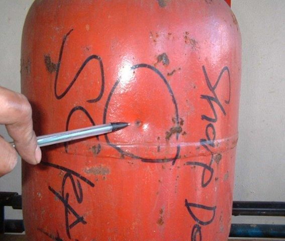
The World LP Gas Association
  The World LP Gas Association was established in 1987 in Dublin, Ireland, under the initial name of The World LPG
  Forum.

  The World LP Gas unites the broad interests of the vast worldwide LP Gas industry in one organisation. It was granted
  Category II Consultative Status with the United Nations Economic and Social Council in 1989.

  The World LP Gas Association exists to provide representation of LP Gas use through leadership of the industry
  worldwide.

Acknowledgements
  The WLPGA would like to thank all those who have contributed to this publication which was initially drafted by Vic
  Mariñas, an independent consultant who was contracted by the WLPGA to undertake this work. The draft was
  reviewed by David Tyler (WLPGA) together with a small review committee which included Nikos Xydas
  (WLPGA/AEGPL), Renzo Bee (Total), and Ron Kearney (Consultant).
Guide to Good Industry Practices
LP Gas Cylinder Management
Contents

         Chapter One
         Background

         Chapter Two
         LP Gas Cylinder Management

         Chapter Three
         Selection of LP Gas Cylinder
            3.1 General
            3.2 Types of Valve
            3.3 Standardisation

         Chapter Four
         Cylinder Design
            4.1 General
            4.2 Design Code
            4.3 Design Pressure
            4.4 Wall Thickness and Cylinder Diameter
            4.5 Construction

         Chapter Five
         Manufacturing
           5.1 General
           5.2 Material
           5.3 Welding
           5.4 Post-Weld Heat treatment
           5.5 Surface Preparation
           5.6 Zinc Metal Spray
           5.7 Painting
           5.8 Internal Cleaning and Drying
           5.9 Valving and Torque Application
           5.10 Tare Weighing
           5.11 Checking of Water Capacity
           5.12 Testing and Examination
           5.13 Stamp Markings and Labelling

Page 2                                     Guide to Good Industry Practices - LP Gas Cylinder Management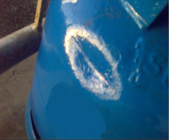
Chapter Six
      Cylinder Filling
          6.1 General
          6.2 Cylinder Inspection prior to Filling
          6.3 Filling of Cylinder
          6.4 Post-Filling Procedure

      Chapter Seven
      Maintenance, Repair and Requalification
        7.1 General
        7.2 Cylinder Defects and Damages
        7.3 Cylinder Cleaning and Surface Treatment
        7.4 Repair
        7.5 Requalification
        7.6 Repair of Valves

      Chapter Eight
      Cylinder Scrapping

      Appendix One
      LP Gas Properties and Hazards

      Appendix Two
      Calculation for Maximum Fill Quantity

      Appendix Three
      Description of Steel Cylinder Defects

      Appendix Four
      Procedures for Gas-Freeing Cylinders

      Appendix Five
      Procedures for De-denting of Cylinders

      Appendix Six
      Procedure for Requalification of Cylinders

      References

Guide to Good Industry Practices - LP Gas Cylinder Management   Page 3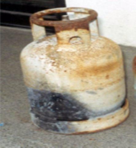
Page 4 Guide to Good Industry Practices - LP Gas Cylinder Management
Chapter One

   Background

      The WLPGA is committed to providing independent advice to LP Gas stakeholders to ensure safety in the operation of
      LP Gas equipment.

      The two WLPGA guides - Best Business Practices and Best Safety Practices - have been used extensively during the last
      ten years all over the world to provide guidance across all areas of the LP Gas industry.

      These two guides have been designed to provide general advice to all stakeholders on best practices throughout the
      supply and distribution chain.

      Following the success of these guides it has been decided to develop and publish more detailed advice in certain areas
      of the supply and distribution chain that are considered more critical and where more prescriptive advice would be
      helpful.

      The first of these areas is the subject of LP Gas Cylinder Management, which addresses the life cycle of an LP Gas
      cylinder from acquisition through to disposal.

      This document deals with the general management of cylinders and covers some specific guidelines related to steel
      cylinders which comprise the majority of the LP Gas cylinders in circulation. For specific issues on other types of
      cylinders i.e. aluminium, composite, aerosol or disposal cartridges, etc. other references should be referred to. (Note:
      for composite cylinders, reference should also be made to the WLPGA document "Composite Cylinders, Facts and
      Guidelines").

      The guidelines in this document are adopted from globally recognised LP Gas Standards and Codes of Practice as well
      as using best practices from major LP Gas companies. It is recommended that these guidelines be applied in
      conjunction with any local laws or regulations to enhance the overall safety performance of your LP Gas business.

Guide to Good Industry Practices - LP Gas Cylinder Management                                                    Page 5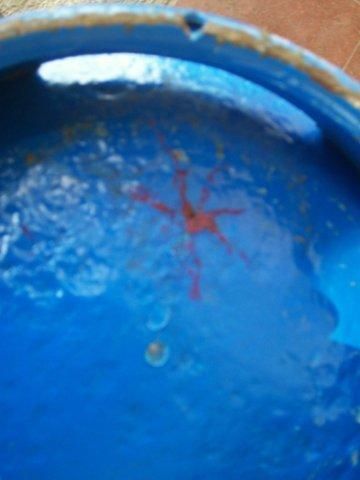
Page 6 Guide to Good Industry Practices - LP Gas Cylinder Management
Chapter Two
LP Gas Cylinder Management
LP Gas is one of those unique products where the packaging often costs more than the contents.
The majority of LP Gas consumed around the world is delivered to the consumer in steel cylinders of various sizes and
types.
The cylinder is an important asset of the business that not only needs to be protected for commercial reasons it is also
required to withstand all the challenges of the distribution chain in order to keep the contents secure and safe.
This guide focuses on the management of LP Gas cylinders right through the life cycle, including the key principles of
selection, design, manufacturing, filling, maintenance, repair & requalification and disposal. There are six main
sections:
Selection of LP Gas cylinder
Cylinder Design
Manufacturing
Cylinder Filling
Maintenance, Repair and Requalification
Cylinder Scrapping
Guide to Good Industry Practices - LP Gas Cylinder Management Page 7Page 8 Guide to Good Industry Practices - LP Gas Cylinder Management
Chapter Three
Selection of LP Gas Cylinder
3.1 General
LP Gas cylinders have for many years been manufactured from metal (mainly steel with a small proportion from
aluminium) in different sizes and with different valve types. The design has essentially remained unchanged for so
long that one criticism of the industry has been its inability to create a more desirable consumer value proposition. In
recent years however, apart from aluminium, there has been the development and introduction of light weight steel -
some with plastic components - and composite cylinders which offer several advantages over metal cylinders. With
different types of cylinders now available in the market it is critical to choose the right one for your business. This will
largely depend on the particular application, environment, budget and market conditions where it will be used.
3.1.1 Size
LP Gas cylinders can come in many different sizes depending on the application. The gross weight of an LP Gas cylinder
is often one of the limiting factors in selecting the size, especially for domestic applications. The diameter is also a very
important factor because it has implications with the dimensions of the conveyors in the filling plant, and the pallets
and racks used for storage etc.
For domestic use, cylinders typically will have capacities ranging from 4kg to 15kg whereas for commercial and
industrial use, these will range from 45kg to 50kg. Smaller cylinders i.e. 1kg to 3kg capacities are used for camping
equipment and in developing countries where they often serve as an entry level for LP Gas applications in low income
households - mainly for cooking. LP Gas cylinders will almost always be used in the vertical position although forklift
cylinders are typically designed to be used horizontally with capacities ranging from 15kg to 22kg.
3.1.2 Material
The majority of cylinders in the market today are made of steel. They are robust and can withstand rough
handling better. There is generally no internal corrosion (unless there is water inside the cylinder) but they
can corrode externally. Steel cylinders can last many years with proper care and maintenance and are
essentially repairable if they become damaged. Steel cylinders are known to last up to 50 years in countries
where cylinders are handled properly, where cross filling is non-existent and where cylinders are transported
properly e.g. in pallets.
Some cylinders are made of aluminium which is lighter than steel. However, impurities in LP Gas i.e. sodium
hydroxide, are known to corrode aluminium and therefore restricts their use only to certain qualities and
grades of LP Gas.
Composite cylinders are recent developments. They can be up to 70% lighter than steel cylinders and are
translucent which allow consumers see the level of liquid LP Gas inside the cylinder. Being made of composite
material, they are non-corrosive both internally and externally and are easier to keep clean. They also do not
explode when engulfed in fire. The price gap between composite and steel cylinders has fallen over recent
years to make composite cylinders an increasingly attractive alternative to steel cylinders. For more advice on
managing Composite Cylinders refer to the WLPGA publication ‘Composite Cylinders, Facts and Guidelines’.
Guide to Good Industry Practices - LP Gas Cylinder Management Page 93.2 Cylinder Valves
There two basic types of LP Gas cylinder valves for vapour service, namely, self-closing, clip-on valves and hand wheel
operated valves. They can come with or without pressure relief valves depending on local regulations.
3.2.1 Self-Closing, Clip-on Valve
These are typically used for domestic cylinders where low cost and fit for service valves are required. Common types
in the market are compact, bayonet, or snap on (snap tight) valves.
They can be fitted with excess flow limiters and/or anti-dirt tubes (also called eduction tubes). Because these valves
are open-topped, plastic dust caps are recommended to be fitted during storage and transportation to prevent entry
of foreign matter.
3.2.2 Hand Wheel Operated Valve
These valves are used both with domestic and commercial cylinders and are designed for different applications i.e.
liquid fill, liquid service and vapour service. The outlet connection of hand wheel operated valves can come in
different forms e.g. CGA 510 (or F.Pol), CGA 555 (or M.Pol), ACME, NPT, etc. When both vapour and liquid connections
are on the same valve, they must be designed differently for clear distinction. Liquid service valves are fitted with a
tube and an excess flow limiter.
Hand wheel operated valves can accidentally be opened and it is recommended to fit a gas tight plug after filling while
the cylinder is in transport or storage.
3.2.3 Cylinder Connection
The valve threads for the cylinder connection are tapered in design and may have different specifications. It is
important that the valve thread specifications are compatible with the bung specification (see 4.5.3). The common
specifications used are ¾ inch NGT (National Gas Taper), DIN 477 and ¾ inch SGT (Special Gas Taper). Some countries
require a standard cylinder connection thread for all cylinders. In countries where this is not specified, it is important
to ensure that valves with different cylinder connection threads are not intermixed in the same cylinder population.
3.3 Standardisation
Cylinders (and valves) for individual companies operating in a particular location should ideally be limited to a few
standard types and sizes as much as possible. This will allow:
Filling plants to automate facilities and operate efficiently
Distribution trucks to optimise carrying capacity
Distributors’ to have uniform cylinder cages and display racks
Procurement to achieve scale in sourcing
All these will lead to a more efficient business.
Page 10 Guide to Good Industry Practices - LP Gas Cylinder ManagementChapter Four
Cylinder Design
4.1 General
LP Gas is a highly flammable product that is commonly stored under pressure. Any leakage of LP Gas from its
container has a potential to cause fire and injury. For this reason, cylinders should be designed and manufactured in
accordance to recognised codes and standards.
The following guidelines apply to welded steel cylinders with water capacity of up to 150 litres.
4.2 Design Code
LP Gas cylinders should be designed and manufactured to established international standards such as ISO 22991 or
equivalent (e.g. DOT, EN 1442, etc.). Where local regulations require the use of national standards or alternative
codes it is important to confirm that they at least equal the requirements of ISO22991.
4.3 Design Pressure
The design pressure of the cylinder is based on the vapour pressure of the product to be filled. In countries
where the product vapour pressure is not strictly controlled, or is variable in practice i.e. different blends of
butane/propane mix are supplied, then it should be assumed that product with vapour pressure of up to
propane could be filled. Cylinders should therefore be designed for propane service.
In countries where the vapour pressures of butane or LP Gas mixtures are controlled and there is confidence
that the supply will remain unchanged, the butane developed pressure or the equivalent developed pressure
relating to the mixture supplied, may be used in the calculation of wall thickness.
The vapour pressure developed is dependent on the local climatic conditions i.e. the higher the temperature,
the higher the vapour pressure. Reference should be made with the relevant standards to determine the
appropriate reference temperatures for particular countries. If a low vapour pressure supply changes to a
higher vapour pressure supply, and cylinders have been designed for the lower vapour pressure, then the
cylinders may not be fit for purpose in which case they will have to be replaced with cylinders designed for
the higher vapour pressure.
Where a local requirement calls for DOT cylinders a test pressure of 480 psig is to be used except where local
high vapour pressure product requires a test pressure of 520 psig.
4.4 Wall Thickness and Cylinder Diameter
The wall thickness of the cylinder is calculated using the formula prescribed by the standard or code used. Aside from
the design pressure, other factors affecting the minimum wall thickness include the yield strength of the material used
and diameter of the cylinder. Wall thickness will decrease with higher yield strength material whereas it will increase if
the cylinder diameter increases. One benefit of designing to minimise wall thickness is the resultant reduction of the
cylinder weight though this has to be evaluated against the cost of using high yield strength materials. It is therefore
Guide to Good Industry Practices - LP Gas Cylinder Management Page 11important to carefully consider the material used and cylinder diameter when designing cylinders to arrive at an
optimum design.
Some codes specify an absolute minimum wall thickness regardless of the design pressure. In ISO 22991 for example,
the over-riding minimum thickness limit for cylinders with a diameter greater than 150 mm is 1.5mm.
4.5 Construction
4.5.1 Parts of a Cylinder
A LP Gas cylinder consists of a few basic parts, namely – shroud (collar or handle), bung, body and foot ring. Each part
has a specific function and should be designed and manufactured to meet its purpose. A poor design can result in
cylinders being easily damaged and/or injury to users.
to suit valve
shroud
bung
cylinder D
base ring
9 mm min.
D+5 mm
Fig 1 Key parts of a Cylinder
4.5.2 Body
The cylinder body holds the contents of the cylinder. It is the main component which is subjected to the
pressure developed by LP Gas inside the cylinder.
The body is designed concave to withstand pressure with either tori-spherical or semi-ellipsoidal ends. The
wall thickness of the body is calculated using the formula prescribed by the design code (see 4.2). The
capacity of the body is expressed in litres of water capacity. When designing the LP Gas capacity of the
cylinder, the type of product, assessed temperature of the location (see 4.3), and filling tolerance (see
Appendix 2 Table A.2.4 if not prescribed by local regulations) should be considered in the calculation. As a
rule, the maximum LP Gas content should not be more than 97% of its water capacity at the assessed
temperature.
The body is generally made in either a two or three piece design depending on the size and application (see
Fig. 2 and 3). Two-piece construction is common for domestic cylinders which consist of an upper and bottom
cup. Higher capacity cylinders (i.e. cylinders for commercial and forklift applications) will generally require
three-piece construction to avoid having to draw the cups too deep to meet the capacity. Cylinders are
mainly designed for use in an upright position although some applications will require the cylinder to be
horizontal (i.e. forklift cylinders). As the name suggests they are cylindrical in shape with typically only one
opening, (some liquid withdrawal valves have two openings) where the valve is positioned.
Page 12 Guide to Good Industry Practices - LP Gas Cylinder ManagementFig. 2 Two-piece body Fig. 3 Three-piece body
4.5.3 Bung
The bung (also called the boss or neck-ring) is the opening on the cylinder which provides a connection to the
valve. It should be located on the end of the cylinder and should be clear of any circumferential or
longitudinal welds.
The bung can either be an internal type or an external type and it should be designed to minimise the
protrusion of the bung above the cylinder unless it is designed for a screw on cap.
The thread should be specified to suit the valve thread intended to be used. It is recommended that only one
thread specification should be used for the entire cylinder population to avoid intermixing of different valves.
For cylinders where the cooking appliance is directly connected on top of the valve e.g. 2kg to 3kg cylinder,
the concentricity of the bung to the vertical axis of the cylinder is critical and should be kept within a
maximum tolerance of 3mm.
4.5.4 Shroud
The purpose of the shroud (also called a collar) is to protect the valve from damage due to impact and when
stacking cylinders on top of each other. It is also fitted to enable the cylinder to be handled. In the absence of
a shroud, the valve should be protected using a removal cap which is also to be fitted when the cylinder is in
transit.
Shrouds should be designed so that regulators can be connected easily and that the LP Gas hose is not bent
when the regulator is connected.
Cylinders with self-closing clip-on valves typically will have shrouds totally encircling the valve while cylinders
with hand wheel operated valves will have shrouds with openings to accommodate the connection of
regulators.
The shroud should also be designed to allow one cylinder to be stacked on top of the other without the
bottom of the upper cylinder touching the valve of the lower cylinder. The material should be robust enough
to support the cylinders above it. There may be up to four cylinders stacked on top of the cylinder so the total
gross weight of these should be accommodated by the shroud of the bottom one.
Shrouds should be fully welded to the cylinder unless the country legislation dictates otherwise. The weld
attachments should be designed to prevent water being trapped which might lead to corrosion.
Hand holes in the shroud should be provided to facilitate handling of the cylinders. They should be designed
to provide a comfortable grip when lifting and carrying the cylinder and prevent potential injury to the user.
If a pressure relief valve is fitted to the valve there should be an opening in the shroud to allow vented LP Gas
to escape.
An example of a typical recommended shroud design is shown in 4.5.1 Fig.1. In practice the actual design will vary
according to the manufacturer.
Guide to Good Industry Practices - LP Gas Cylinder Management Page 134.5.5 Foot Ring
The foot ring should provide stability to the cylinder when standing alone or if stacked on top of another
cylinder. It also protects the underside of the body from touching the ground.
Foot rings should be designed larger than the outside diameter of the cylinder in order to minimise damage
to the cylinder walls during handling and transit.
The foot ring should be designed to prevent water being trapped which might lead to corrosion. It should also
have ventilation holes to prevent condensation building up on the underside of the body of the cylinder.
The material should be of sufficient thickness to resist deformation of the foot ring during handling and to
support the weight of cylinders stacked above it.
An example of a recommended foot ring design is shown in 4.5.1 Fig.1. In practice the actual design will vary according
to the manufacturer.
Page 14 Guide to Good Industry Practices - LP Gas Cylinder ManagementChapter Five
Manufacturing
5.1 General
Only manufacturers certified to ISO 9001 that can demonstrate their ability to producing cylinders that meet
quality standards should be selected. Furthermore, manufacturers selected should have the certifications to
produce to specific codes and standards i.e. DOT, EN, etc.
It is important also to ensure that manufacturers comply with the requirements of the design code and
manufacturing specifications by appointing an independent inspection authority during and post
manufacturing to verify compliance. DOT specifies the manufacturing inspection for cylinders which should
be carried out by DOT approved inspectors.
Prior to the commencement of production, the manufacturer and buyer should agree/approve the
applicable design code or standards, manufacturing drawings and specifications and destructive and non-
destructive testing requirements.
5.2 Material
5.2.1 Pressure Parts
The grade of steel used in cylinder manufacture must be compatible with the intended grade of gas in
service. It should be suitable for drawing and welding and when used in locations with sub-zero temperature
o
conditions, they should not be brittle at minus 20 C.
The manufacturer should have the certificates to show the chemical analysis and the details of the
mechanical properties of the steel supplied for construction of the pressure parts of the cylinder. These
material certificates should be kept on file for future reference in case of any incident concerning material
defects. Materials used for steel cylinders will typically have chemical analysis not exceeding the following
values %:
o Carbon 0.250%
o Silicon 0.450%
o Manganese 1.600%
o Phosphorus 0.040%
o Sulphur 0.040%
Where micro-alloying elements are used, their presence and amounts should be reported in the steel
manufacturer’s certificate.
Materials should be examined and tested prior to manufacture to confirm their suitability for use for welded
steel cylinders. All test reports should be kept on file for future reference.
Examples of steel specifications used for welded steel cylinder manufacturing includes ISO 4978, EN 10120 or
JIS G3116
Guide to Good Industry Practices - LP Gas Cylinder Management Page 155.2.2 Non-Pressure Parts
The material used for other parts of the cylinder except the bung i.e. shroud and foot ring, should be of compatible
weldable material.
5.2.3 Bung
The bung should be made of compatible weldable material.
5.2.4 Welding Consumables
The welding consumables should be capable of producing a consistent weld with a minimum tensile strength
equal to that specified for the parent material in the finished cylinder.
5.3 Welding
5.3.1 Welding Qualification
All welders and welding operators should be qualified and certified. The welding procedures should be
agreed by the manufacturer and buyer before the start of production.
Records of welding qualification should be kept on file by the manufacturer.
Weld approval tests should be made in a manner that the welds should be representative of that made in
actual production.
Welders should have passed the approval tests for the specific type of work and procedure specification
concerned.
Welders should be re-qualified and re-certified if the specific type of work or procedure has not been done by
the welder for three months or more.
5.3.2 Metal Preparation prior to Welding
The surface to be welded should be free of dirt, oil, grease, mill scale, rust or drawing compound before
welding. This will help prevent welding defects such as lack of fusion, inclusions, gas pores, etc.
Surfaces on both sides of joints (circumferential and longitudinal) to be welded should be cleaned by
chemical washing and/or by mechanical wire brushing.
5.3.3 Welding Procedure and Parameters
The welding procedure for the circumferential and longitudinal body joints should be submerged arc welding.
It should be done by using a fully mechanized, semi-automatic or automatic process to provide a consistent
and reproducible weld quality.
Welding of the bung, shroud and foot ring should be by shielded metal arc welding, gas metal arc welding or
other welding processes that meet the requirements of this section.
Circumferential joints should be butt welded with one member offset to form an integral backing strip
creating a joggle butt weld. The external surface of the cylinder is smooth and the components e.g. top and
bottom halves of a two piece cylinder, correctly line up. They should be made by a two pass welding
procedure with one weld laid on top of the first welding pass such that the joint space between the two
components is filled with welding material. There should be no more than two circumferential joints per
cylinder.
Longitudinal seams should be butt jointed. Permanent backing strips should not be used for longitudinal
joints. There should be no more than one longitudinal joint per cylinder.
Circumferential and longitudinal welds should show complete penetration and fusion.
Page 16 Guide to Good Industry Practices - LP Gas Cylinder ManagementThe excess thickness should be such that weld integrity is not compromised. Longitudinal welds should be
continuous straight beads correctly aligned to the butt joint without demonstrating welding defects i.e. burn
through or internal concavity.
The profiles of all welds should be smooth and have a uniform contour throughout each run i.e. without
concave or excessive convex contour. Each weld should fuse into the parent metal without undercutting or
abrupt irregularity.
The welding process should be controlled to ensure minimum weld spatter.
5.3.4 Weld Repairs
If during the hydrostatic or tightness tests minor leaks are found in the welding, the defect may be repaired
by automatic welding in accordance to the agreed repair procedure. Bung welds should however not be
repaired.
After weld repair, cylinders should undergo post weld heat treatment and hydrostatic test again (refer also
to 5.13).
5.4 Post-Weld Heat Treatment
All cylinders must be subject to post weld heat treatment after completion of forming and welding processes
to relieve residual stresses from fabrication and restore/enhance the mechanical properties of the metal.
The heat treatment applied may either be stress relieving or a normalising process as defined in ISO 4706 or a
comparable standard. Normalising process is the recommended best practice where the cylinder is heated to
a uniform temperature above the upper critical point of the steel (typically 900 deg C or above) to regenerate
or homogenise the metallurgical structure of the steel and then cooled in a controlled or still air atmosphere.
The heat treatment must be carried out in a reducing atmosphere in order to minimise scale formation and
achieve a clean internal condition. The furnace should be equipped with appropriate temperature monitoring
and recording instruments.
The manufacturer must maintain records to indicate that the cylinders have been heat-treated to indicate the
adequacy of the heat-treatment process used.
Localised heat treatment must not be used.
5.5 Surface Preparation
Cylinder surfaces must be free of scale, rust and oil before the application of any surface coating. This will
ensure good adherence and longer life of the surface coating.
All openings and threaded connections must be effectively sealed before any surface cleaning operation to
prevent entry of any foreign particles.
External surfaces must be grit-blasted until they are clean and uniformly grey in appearance to SA 2 ½ (ISO
8501-1) and a medium surface roughness in accordance with ISO 8503-1 suitable for the adhesion of a
sprayed zinc metal coating.
Steel shots or grits or their combinations thereof are used for surface blasting. They should be replaced as
necessary to ensure that the surface preparation always meets the requirements given above.
Shot blasted cylinders must be subject to painting within three hours to ensure the surface remains clean and
free from rust.
Guide to Good Industry Practices - LP Gas Cylinder Management Page 175.6 Zinc Metal Spray
5.6.1 General
The purpose of applying zinc metal spray is to prevent external corrosion and ensure longer life of the
cylinder. The decision to specify zinc metal spray is often a question of ambient conditions and economics.
The cost should be compared with the result of cylinder corrosion experienced in a particular location. If a
high proportion of the cylinders in the location show evidence of external corrosion then the use of zinc
metal spray is probably justified.
There are also safety reasons for applying zinc metal spray i.e. where the location experiences high external
corrosion rates - for example near the coast where sea water corrosion is likely - this can lead to LP Gas
leakage through the cylinder wall which sometimes can be catastrophic if a large area of metal has failed.
5.6.2 Process
If zinc metal spray is required, it should be applied to the external surfaces of cylinders, including the shroud
and foot ring, within three hours of grit blasting.
A minimum coating of 40 microns should be evenly applied in accordance with EN 22063. The area beneath
and inside the foot ring which is more prone to corrosion should be coated to a minimum thickness of 100
microns.
Adhesion test on the zinc metal spray should be carried out in accordance to EN 22063 after application.
5.7 Painting
Cylinders should be sprayed with a suitable top coat (i.e. epoxy-based paint) that has good impact and
scratch resistance to maintain the appearance of the cylinder. A minimum coating of 50 microns dry film
thickness should be applied and dried in accordance to the paint manufacturer’s instructions. For cylinders
without zinc metal spray, a minimum coating of 80 microns dry film thickness should be applied.
After drying the paint surface should present a smooth opaque finish free from streaks and sagging. Isolating
the painting area from dust and dirt will help keep the finished surface shiny and clean. If properly applied,
the paint should be capable of retaining a good finish free from flaking and peeling for several years.
5.8 Powder Costing
Powder painting may be used as an alternative to zinc metal spray and paint combination. Care should be taken to
ensure that the powder paint is applied on a moisture-free surface to ensure good adhesion on the cylinder and to
eliminate any subsurface corrosion. Usually powder coating produces better results.
5.9 Internal Cleaning and Drying
After completion of the surface treatment, threaded components i.e. bung, should be gauged and cleaned by
running a tap with the correct thread form into connections to remove grit, zinc, paint etc. from the threads.
The cleaning operation should not remove parent metal from the threads.
Moisture, loose rust and scale etc. should be removed from the interior of the cylinder by a vacuum pipe and
the cleanliness checked using an inspection lamp.
Cylinders which are not immediately fitted with a valve should be sealed at the bung with a plug to prevent
ingress of moisture or foreign material.
Page 18 Guide to Good Industry Practices - LP Gas Cylinder Management5.10 Valving and Torque Application
Cylinder valves should be fitted immediately after internal cleaning and drying has been completed.
The sealing compound used should be suitable for use with LP Gas and should be applied to the valve threads
avoiding entry of the compound into any part of the valve or the cylinder. The compound used should be a
liquid thread sealant which forms an effective seal and remains plastic in service.
Valves should be fitted correctly to avoid damage to threads and tightened using a torque wrench to within
the limits specified by the valve manufacturer
5.11 Tare Weighing
The finished cylinder complete with valve, shroud and foot ring should be weighed on an electronic scale with an
accuracy and repeatability of at least 0.1% (1 in 1000). Scales should be approved and regularly checked for accuracy
(at least once per shift using standard weights over the measuring range). The tare weight to be recorded on the
cylinder should be that indicated on the scale rounded down to the nearest lower 0.10 kg.
5.12 Checking of Water Capacity
Cylinders should be checked for water capacity to ensure compliance with the minimum value shown on the
manufacturing drawing. There is no negative tolerance in measured water capacity. If a lower value is discovered in
the sample check cylinder then all cylinders produced after the previously satisfactorily checked cylinder must be
individually checked. Cylinders which have less than the required minimum capacity must be rejected and scrapped
(see Chapter Eight).
5.13 Testing and Examination
Cylinders should be subjected to the required tests and examination following the methods and procedures
stated in the design code i.e. ISO 22991. These tests may include:
o Mechanical test of parent metal and welds – for checking the mechanical properties of the pressure
parts of the cylinder.
o Burst Test under hydraulic pressure – for checking the ability of the cylinder to contain the pressure
of LP Gas to a certain level. The results indicate the other details of the mechanical properties not
shown by mechanical tests.
o Pressure Test under hydraulic pressure – checking for leaks in the weld and other parts of the
cylinder. Cylinders should also not show any signs of permanent deformation. This test should be
applied to 100% of the cylinders manufactured.
o Radiographic and Macro examination - checking for defects in the welds such as lack of penetration
or fusion, cracks, inclusions, gas pores, etc.
Test results should be documented. Cylinders failing the test should be referred to the inspection authority
for appropriate action.
If any leakage occurs, the cylinder should be regarded as having failed the test. Leak detection should be by
immersion in a water bath or other test of equal sensitivity. If water bath method is used, the water should
be maintained clean and clear enough to detect leakage. The water in the bath should also be reasonably
stable to allow for leaks to be clearly detected i.e. little turbulence.
If cylinder valves are fitted by the manufacturer, a pneumatic test should be conducted to check for gas
tightness at a pressure agreed between the manufacturer and buyer
Guide to Good Industry Practices - LP Gas Cylinder Management Page 195.14 Stamp Markings and Labelling
5.14.1 General
Cylinders should be stamped or stencilled with manufacturing, operational and certification markings as
required by local regulations. In their absence, 5.14.2 and 5.14.3 should apply.
Stamp markings should be applied permanently and legibly without affecting the integrity of the cylinder e.g.
on the shroud or other permanent attachments.
The characters in the stamp markings should be preferably at least 5 mm in height. On cylinders with an
outside diameter less than 140 mm, this height may be reduced, but in no case should the characters be less
than 2.5 mm in height.
The depth of the characters in the stamp markings made by any method should be such that they are legible
and durable under all operating conditions.
5.14.2 Stamped Markings
The following stamp markings should be provided on the cylinder:
Manufacturer’s identification
Design code
Design pressure clearly stating product to be used (Propane or Butane)
Test pressure
Serial number
Date of manufacture/initial test date (month-year)
Tare weight
Water capacity
Identification of content
Certification (if require)
Name of cylinder owner (mandatory)
Brand name embossed (owner’s name may be different from the brand name) e.g. in Vietnam for example,
cylinders branded “Saigon Gas” belong to Totalgas.
5.14.3 Labels or Stencilled Markings
Aside from stamped markings, the following should also be labelled or stencilled legibly on a prominent part of the
cylinder:
Identity of content
Net contents of cylinder
Date of next requalification
Tare weight
Identification of content
Danger warning sign
Brand name (optional)
Other safety information as required
Much of this information can also be incorporated in the form of bar codes that can be fitted to cylinders to facilitate
tracking and gathering other information at the filling plant.
Page 20 Guide to Good Industry Practices - LP Gas Cylinder ManagementChapter Six
Cylinder Filling
6.1 General
Filling of LP Gas cylinders is a safety critical activity and must be carried out only by trained and competent
workers in a facility designed specifically for cylinder filling. The cylinder filling facility should be well
ventilated and clear of any potential hazards while filling is occurring. Workers must fully understand the
emergency procedures and comply with the requirements with regard to personal protection equipment
(PPE) while on duty.
Filling of cylinders should comply with local regulations. The correct specifications and quantity of LP Gas
should be filled. Cylinders must never be overfilled (see 6.5). Scales used for check weighing should be
serviced regularly and checked for fill accuracy and tolerance before and during cylinder filling operation.
Filling plants with high capacity are usually fully automated with little manual handling of cylinders required.
However, for small filling facilities which are typically not automated, manual handling of cylinders could be a
major activity and should be carried out with care to avoid damage to the cylinder and injury to workers.
6.2 Cylinder Inspection prior to Filling
All cylinders must be inspected prior to filling to ensure only safe and suitable cylinders are refilled. Particular
attention should be given to the underside of the cylinder during inspection. Cylinders inspected can be
segregated into several categories i.e.:
o Leaking cylinders – they must be de-pressurised to atmospheric pressure and gas freed as soon as is
practicable.
o Cylinders due for periodic inspection and testing.
o Defective/faulty cylinders, e.g. serious dents, bulges, gouges, fire damaged, damaged valves, valves
with missing consumer seal, etc.
o Cylinders with partial or worn markings/finish.
o Cylinders containing air, e.g. new/reconditioned cylinders.
o Cylinders owned by third parties where there is no agreement to fill or maintain them. These should
be returned to the owner/filler.
o Cylinders suitable for filling. These cylinders should be sorted according to capacity and product to
fill.
Cylinders with defects/faults should be assessed if they can still be repaired and if it is economically
practicable to do so. Where cylinders are deemed not repairable, they should be scrapped (see Chapter
Eight).
6.3 Filling of Cylinders
Only suitable cylinders meeting the required safety standards and with clearly marked tare weights and
requalification dates should be filled.
Guide to Good Industry Practices - LP Gas Cylinder Management Page 21 Cylinders can be filled by weight or by volume. When filling is by weight, the tare weight of the cylinder
should be accurately set on the filling scales. When filling is by volume, the cylinder should be emptied of
liquid before filling unless the cylinder is fitted with a safe fill level device (e.g. dip tube).
Every time the cylinder is connected to the filling equipment, leak checks should be undertaken to ensure the
connections are safely and correctly carried out. Any faults, which develop during filling, should be promptly
corrected by the operator and reported to a supervisor who should investigate the problem and implement
any further necessary corrective action.
6.4 Post-Filling Procedure
Unless the filling scales themselves are approved by the appropriate local regulatory authority and checked
daily using appropriate procedures, every cylinder must be check-weighed for accurate fill/tolerance etc.
This may be made by manually weighing or by using an automated weight or level checking system.
Over-filled cylinders must have the excess product removed as soon as is practicable in a safe and controlled
manner, i.e. into an enclosed vacuum system or by venting into a vent stack or exhaust fan system connected
to a vent stack.
Under-filled cylinders must be returned for fill correction.
All cylinders including their valves must be thoroughly checked for leaks. Leaks detected should be made safe
as soon as practicable.
All hand-wheel-operated valves must be leak tested in both the open and closed positions. Faulty seals
should be replaced where necessary.
Self-closing clip-on valves must have the main gas seal and the customer seal checked.
All valves must also be checked for distortion to ensure that it will be possible to properly attach a regulator
Valve protection/sealing caps/gas-tight plugs/labels and warrantee seals should be attached to cylinders
before despatch.
Hazard warning information as required by local regulations must be present on the cylinder and clearly
legible.
If the cylinder needs to be gas-freed, it must be done in a safe and controlled manner.
If there is reason to suspect air is in the cylinder, then it should be checked e.g. by noting the vapour
pressure. If air is indicated by a significant overpressure, it should be removed by venting through a suitable
venting system.
6.5 Maximum Fill Quantity
LP Gas has a high coefficient of thermal expansion. If overfilled, a cylinder could become hydraulically full
when the temperature subsequently rises. The consequent increase in the hydraulic pressure could lead to
liquid LP Gas escaping from the pressure relief valve (if fitted) and/or to distortion or bursting of the cylinder.
Fill quantities must be closely controlled.
After filling a cylinder there must be enough vapour space left to cope with expansion of the liquid content
that would occur when the temperature reached the highest level expected in normal service i.e., the
“assessed temperature” and to allow for filling tolerances or inaccuracies in the filling method. (The assessed
temperature to be used depends on the climatic conditions in the area where the cylinder is to be used and is
related to the recorded maximum shade temperature).
The liquid level must leave at least 3% of the cylinder’s water capacity free of liquid at the assessed
temperature. (Beware of the influence of dip tubes fitted to compact valves).
Overfilling must be avoided by ensuring that the amount of LP Gas filled into a cylinder does not exceed that
calculated as shown in Appendix Two.
Page 22 Guide to Good Industry Practices - LP Gas Cylinder ManagementChapter Seven
Maintenance, Repair and Periodic Requalification
7.1 General
The physical condition of LP Gas cylinders can deteriorate with poor handling, use of inappropriate
distribution equipment, and continued use and exposure to the elements. Regular maintenance, repair and
requalification are necessary to ensure that they remain fit for service. This can be achieved by inspecting and
then segregating cylinders with defects and damage for appropriate action when they are brought into the
filling plant for refilling.
Maintenance and repair work can be done in a suitable location inside the filling plant/depot. However, some
repairs may require special equipment and competences. Only qualified contractors with properly equipped
workshops and manned by trained workers should be selected for this type of work.
The supervision of work and decisions on fitness for service should only be undertaken by Competent
Persons. Many of the operations can be hazardous and/or noisy and due care should be taken to protect
workers against the assessed risks.
Cylinder maintenance and repair entails cost and therefore should be carried out efficiently and properly.
Otherwise the business performance will be adversely affected. There may be a temptation to save costs by
ignoring maintenance, test and repair. The result is a deteriorating asset base and higher safety risks to
customers.
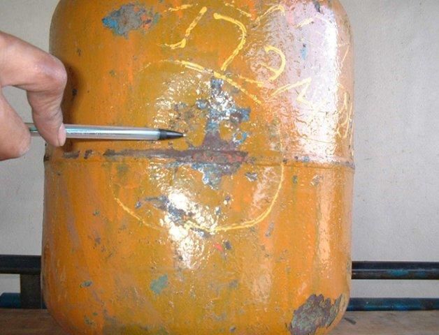
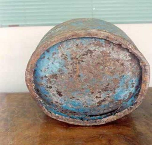
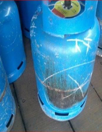
7.2 Cylinder Defects and Damages
7.2.1 Steel Cylinder
Steel cylinders should be inspected for the following defects and damage:
Partial or worn markings/finish
Leaking valves, damaged valves, valves with missing consumer seals, etc
Serious dents, bulges and gouges
Corrosion pits, lines and general corrosion
Fire damage and scorching
Cylinders due for periodic inspection and testing
7.2.2 Cylinder Defects
A description of cylinder defects and damages can be found in Appendix Three. Suggested rejection limits can be
found in ISO 10691:2004. These criteria should be applied by a Competent Person when categorising cylinder defects
for repair or scrap. If a cylinder is badly corroded or damaged, it might not be possible to recover it and it must then
be scrapped.
7.3 Cylinder Cleaning and Surface Treatment
7.3.1 Cylinder Cleaning and Washing
Cylinders covered in dust and grease and other contamination may be subject to cleaning or washing either manually
or through the use of automated washing machines. If surface deposits such as bitumen splashes, concrete splashes,
Guide to Good Industry Practices - LP Gas Cylinder Management Page 23excessive grease etc. cannot be removed by routine cleaning or washing, they should be set aside for hand cleaning or
shot blasting.
7.3.2 Cosmetic Repainting
Care should be taken when deciding to repaint for cosmetic reasons. Often paint is applied to the cylinder
without any surface cleaning. The result is far from a cosmetic improvement. Any painting should only be
done on sound, clean, dry cylinders which have had any loose paint or information or branding stickers
removed; for example by wire brushing, to give a good base for the new paint.
Cylinders for cosmetic repainting need not be gas freed or have the valves removed. However they should
not be overheated to avoid excessive internal pressure build up. Valves should be completely closed and
protected during repainting.
7.3.3 Shot Blasting
Cylinders should be devalved, gas freed and plugged prior to shot blasting. This can be carried out using grit
or shot. Sand blasting is not permitted in view of the associated health hazards. Note that grit/shot blasting
can remove the zinc metal coating from cylinders; care should therefore be taken if the zinc will not be
replaced as part of the cylinder refurbishment process.
Shot blasted cylinders should be subject to repainting within 3 hours to ensure paint is applied on clean and
rust-free surface for better adhesion. See also 5.5 and 5.7.
7.4 Repair
7.4.1 Repair of Minor Defects
Repairs of minor defects, such as bent shrouds or foot rings, can be carried out in a designated part of the filling
plant/depot. Bent shrouds and foot rings can often be straightened rather than replaced. Straightening is a much
cheaper operation than cutting and welding because it avoids hot work, and should always be considered the first
option. Machines are available which use mandrills and hydraulic pressure to re-form the shape. Great care should
be taken to avoid cracking.
7.4.2 Repairs Requiring Valve Removal but no Hot Work
These will require either the contents of the cylinder to be reduced down to atmospheric pressure and the work or
valve replacement undertaken in a designated Zone 1 area, or the cylinder to be fully gas freed either by evacuation or
by using steam or water (see Appendix Four).
7.4.3 Repairs with Hot Work
Cylinders requiring major repair, involving welding and/or de-denting, must be gas freed, tested and certified gas free
before being processed. Only competent cylinder repair specialists, who are commonly third party organisations,
should undertake such repair. For larger operations it might be possible to safely undertake the work in house.
Essential aspects are:
Removal – If collars and foot rings have to be replaced because they are too damaged to repair, they should
be removed using a pneumatic chisel. Do not use flame cutting or grinding which may cause damage to the
cylinder wall.
Fitting new – New collars and foot rings should be of comparable material quality to the originals. They
should be welded only by operators who are formally qualified for the work. Original information contained
on the collar should be retained to ensure a history of the cylinder’s ‘birth certificate’.
Page 24 Guide to Good Industry Practices - LP Gas Cylinder Management Dent removal – Dents can be removed from cylinders by the careful application of external heat together
with internal pressure using an inert gas, e.g. nitrogen. See Appendix Five for the procedure. Do not use
compressed air because of the danger that, despite proper gas free procedures, residual LP Gas remains in
the cylinder and an explosion may result.
All cylinders that have hot work repairs, should be heat treated and hydraulically tested before being put back into
service (see Appendix Five and Appendix Six). Furthermore, they should be subject to inspection procedures
comparable to that specified for new cylinders.
7.5 Requalification
Cylinders must be pressure tested at periodic intervals and re-qualified for a further period of service. The
periodic examination/testing must be performed according to national legal requirements, the requirements
of the code to which the cylinder was manufactured or a local industry standard, whichever is the most
stringent. If no such criteria exist, those of ISO 10464 must be adopted for steel cylinders (see Appendix
Seven).
The requalification scheme shall be fully documented by a competent person and appropriate evidence and
records maintained in support of the scheme. Note that different requalification may be appropriate for
different cylinder types/usage.
In some countries, cylinders are required to be scrapped by law regardless whether they are still in good
condition or not after a specific period of time. This is however not good practice because cylinders can have
a useful life many years beyond that specific period of time if maintained properly.
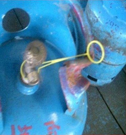
7.6 Repair of Valves
7.6.1 Repair
Other than the replacement of the consumer seals, valves should generally not be repaired unless by the
original manufacturer. If appropriate resources and facilities exist to carry out the repair to appropriate
standards this may be considered.
Replacement parts should be obtained from the original valve manufacturer or from an approved
manufacturer to an equivalent standard to the original parts.
Repaired valves should be subject to the same testing regime required for the original valve. Valves with
damaged pressure relief valves should be scrapped.
7.6.2 Replacement
Valves will suffer from wear and tear and will not last forever. It is therefore recommended that all vertical
valves be replaced at least every 15 years and all hand-wheel valves at least every 20 years with new
approved valves.
Replaced valves have a scrap value and some valve manufacturers will pay to recover these.
Guide to Good Industry Practices - LP Gas Cylinder Management Page 25Page 26 Guide to Good Industry Practices - LP Gas Cylinder Management
Chapter Eight
Cylinder Scrapping
Cylinders that are identified as being outside the rejection limits or beyond the economic cost of repair
compared to the price of new cylinders should be processed for scrap. These cylinders should be gas freed
before being scrapped and made totally unsuitable for further service.
Scrap cylinders have been reported in some locations to be recycled back into the market which can result in
them being unwittingly refilled. This can cause accidents and injury to filling plant operators and users. It is
important therefore to ensure that scrapped cylinders are processed in such a way that they cannot be
reused.
Commonly used methods for destroying scrap cylinders include mechanical crushing, irregular cutting of the
neck of the cylinder, irregular cutting of the body of the cylinder into two or more pieces or piercing, with
hydraulically or pneumatically operated spikes, at least two 50 mm diameter holes in each separate part of
the body of the cylinder. (For guidance, see EN 12816). Mechanical crushing to flatten the scrap cylinders is
also an accepted best practice for scrapping cylinders.
The serial numbers of scrap cylinders should be kept on record, including reasons for scrapping, and also
details of the buyer of scrap cylinders. The data can be used for analysis of root causes and development of
corrective actions to minimise cylinder scrapping rate. The record is also useful to track sources of recycled
scrap cylinders in case these turn up in the plant.
Guide to Good Industry Practices - LP Gas Cylinder Management Page 27Appendix One
LP Gas Properties and Hazards
1.4.1 LP Gas comprises Commercial Propane and Commercial Butane, and mixtures thereof. They are
hydrocarbon gases that can be changed into a liquid and changed back into a gas by the simple application
and release of pressure.
1.4.2 Density - LP Gas vapour is heavier than air and tends to gather at low areas such as drains, pits, cellars and
other depressions. As a colourless liquid, LP Gas occupies around 0.4% of its vapour volume, but is about
half the density of water and will float on water before vaporising.
1.4.3 Cooling effect - LP Gas liquid vaporises and cools rapidly; it can therefore inflict severe cold burns if it
comes in contact with bare skin.
1.4.4 Non-toxic - LP Gas is not toxic. However it has an anaesthetic effect when mixed in high concentrations
with air. The greater the concentration (i.e. as available oxygen declines), the greater the risk of
asphyxiation.
1.4.5 Smell - What people know and recognise as the ‘LP Gas smell’ is usually added to LP Gas before distribution.
This smell can be detected if the LP Gas content of air is as little as 0.4% (or just 20% of the lower limit of
flammability). However, odour is not the only means of detection. Large leaks will also be obvious through
hissing or condensation or frosting around the leak; small leaks will show up as bubbles if detergent mixed
with water is applied to the suspected leak area. NEVER try to detect leaks with a naked flame or other
kinds of ignition.
1.4.6 Flammability - LP Gas can ignite when it forms between 2 and 10% of a vapour/air mixture, so the risks
associated with poor handling, storage or usage should be obvious. Uncontrolled ignition of LP Gas can
cause serious fires or explosions (i.e. if ignited within a confined space). A fire started some distance from
an LP Gas leak can very quickly travel back to the source of the leak itself. An LP Gas cylinder involved in a
fire may overheat and rupture violently. The power and intensity of an LP Gas fire or explosion should never
be underestimated.
1.4.7 Liquid Expansion - LP Gas liquid has a high coefficient of expansion. Tanks, cylinders, pipelines and
equipment must be protected against the high pressure resulting from liquid expansion with temperature
rise.
Page 28 Guide to Good Industry Practices - LP Gas Cylinder ManagementTable 1 overleaf shows some typical physical properties of LP Gas
Typical Characteristics of Propane and Butane COMMERCIAL COMMERCIAL BUTANE
PHYSICAL PROPERTY PROPANE
Litres/tonne of liquid at 15oC 1,965 – 2,019 1,723 – 1,760
Litres/ton of liquid 1,996 – 2,051 1,750 – 1,788
Litres/kg of liquid 1.96 - 2.02 1.72 - 1.76
US barrels/tonne 12.4 – 12.7 10.8 – 11.1
Relative density (to water) of liquid at 15oC 0.50 - 0.51 0.57 - 0.58
Ratio of gas to liquid volume at 15oC and 1015.9 mbar 274 233
Relative density (to air) of vapour at 15oC and 1013.25 mbar 1.40 - 1.55 1.90 - 2.10
Volumes of gas/air mixture at lower limit of flammability from 1 volume of 12,450 12,900
liquid at 15oC and 1015.9 mbar
Boiling point oC Minus 45 Minus 2
Vapour pressure at 0oC barg 4.5 0.9
Vapour pressure at 15oC barg 6.9 1.93
Vapour pressure at 38oC barg 14.5 4.83
Vapour pressure at 45oC barg 17.6 5.86
Upper limit of flammability, % v/v 10.0 9.0
Lower limit of flammability, % v/v 2.2 1.8
3
Gross calorific value MJ/m dry 93.1 121.8
3
BTU/ft dry 2,500 3,270
MJ/kg 50.0 49.3
BTU/lb 21,500 21,200
3
Net calorific value MJ/m dry 86.1 112.9
3
BTUu/ft dry 2,310 3,030
MJ/kg 46.3 45.8
BTU/lb 19,900 19,700
Latent heat of vaporisation kJ/kg at 15 °C 358.2 372.7
Latent heat of vaporisation BTU/lb at 60 °F 154 160
Guide to Good Industry Practices - LP Gas Cylinder Management Page 29Appendix Two
Calculation for Maximum Fill Quantity
A.2.1 Calculation of Safe Filling by Weight
The safe fill weight is given by:
Qf = 0.97 x V x gI - (allowance for tare and filling errors)
Where: Qf = maximum safe fill, kg
V = water capacity of the cylinder, litres
gI = density of LP Gas at the assessed temperature, kg/litre
Densities of commercial LP Gases vary considerably and in the above equation, the lowest value in the product
specification range should be taken to ensure safe filling at all times. Where the proper facilities exist it is possible to
control the density by mixing product. This can give great cost savings in marginal cases, e.g. 14.5 kg versus 15 kg into
a 30 litre cylinder.
The actual safe fill quantity used in filling operations in which the quantity is expressed as a mass should be rounded
down to not less than the nearest 0.1 kg e.g. a calculated safe fill of 11.19 kg would become 11.1 kg.
A.2.2 Calculation of Safe Filling by Volume
The safe filling volume is given by:
Vf = 0.97 x V x gi / gL - (filling and tare weight errors)
Where: Vf = maximum safe fill volume, litres
V = water capacity of cylinder allowing for internal fittings, litres
gi = density of LP Gas at assessed temperature, kg / litre
gL = density of LP Gas at lowest possible fill temperature, kg / litre
Page 30 Guide to Good Industry Practices - LP Gas Cylinder ManagementYou can also read