FUNDAMENTALS - DRAWINGS AND SPECIFICATIONS - BC Campus - LibreTexts
←
→
Page content transcription
If your browser does not render page correctly, please read the page content below
FUNDAMENTALS -
DRAWINGS AND
SPECIFICATIONS

BC Campus
Fundamentals - Drawings and Specifications

                 BC Campus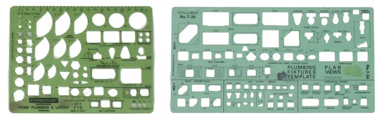
This open text is disseminated via the Open Education Resource (OER) LibreTexts Project (https://LibreTexts.org) and like the
hundreds of other open texts available within this powerful platform, it is licensed to be freely used, adapted, and distributed.
This book is openly licensed which allows you to make changes, save, and print this book as long as the applicable license is
indicated at the bottom of each page.
Instructors can adopt existing LibreTexts texts or Remix them to quickly build course-specific resources to meet the needs of
their students. Unlike traditional textbooks, LibreTexts’ web based origins allow powerful integration of advanced features and
new technologies to support learning.

The LibreTexts mission is to unite students, faculty and scholars in a cooperative effort to develop an easy-to-use online
platform for the construction, customization, and dissemination of OER content to reduce the burdens of unreasonable
textbook costs to our students and society. The LibreTexts project is a multi-institutional collaborative venture to develop the
next generation of open-access texts to improve postsecondary education at all levels of higher learning by developing an
Open Access Resource environment. The project currently consists of 13 independently operating and interconnected libraries
that are constantly being optimized by students, faculty, and outside experts to supplant conventional paper-based books.
These free textbook alternatives are organized within a central environment that is both vertically (from advance to basic level)
and horizontally (across different fields) integrated.
The LibreTexts libraries are Powered by MindTouch® and are supported by the Department of Education Open Textbook Pilot
Project, the UC Davis Office of the Provost, the UC Davis Library, the California State University Affordable Learning
Solutions Program, and Merlot. This material is based upon work supported by the National Science Foundation under Grant
No. 1246120, 1525057, and 1413739. Unless otherwise noted, LibreTexts content is licensed by CC BY-NC-SA 3.0.
Any opinions, findings, and conclusions or recommendations expressed in this material are those of the author(s) and do not
necessarily reflect the views of the National Science Foundation nor the US Department of Education.
Have questions or comments? For information about adoptions or adaptions contact info@LibreTexts.org. More information
on our activities can be found via Facebook (https://facebook.com/Libretexts), Twitter (https://twitter.com/libretexts), or our
blog (http://Blog.Libretexts.org).

                                              This text was compiled on 05/28/2021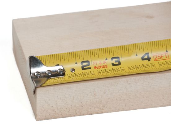
TABLE OF CONTENTS
Some of the most important documents used in the workplace are the technical drawings, diagrams, and schematics that specify how
fabrication and construction tasks will be carried out, or describe the composition and assembly of equipment. One of the essential skills
for anyone involved in a trade is the ability to correctly interpret drawings.

ACKNOWLEDGMENTS AND COPYRIGHT
FOREWORD
INDUSTRY TRAINING AUTHORITY OF BC
SYMBOLS LEGEND
1: DESCRIBE THE DRAFTING TOOLS AND MATERIALS USED IN DRAWING
PLANS
Traditionally, drafters sat at drafting boards and used pencils, pens, compasses, protractors, triangles, and other drafting devices to
prepare a drawing manually. Today, however, most professional drafters use computer-aided drafting (CAD) systems to prepare
drawings. Although drafters use CAD extensively, it is only a tool. Drafters and tradespersons still need knowledge of traditional
drafting tools and techniques.

  1.1: TOOLS
  1.2: DRAFTING MATERIALS
  1.3: COMPUTER DRAFTING PRINTING
  1.E: SELF TEST 1

2: DESCRIBE LINES, LETTERING, AND DIMENSIONING IN DRAWINGS
  2.1: LINE STYLES AND TYPES
  2.2: STANDARD LETTERING
  2.3: PRINCIPLES OF DIMENSIONING
  2.E: SELF-TEST 2

3: USE SCALE RULERS TO DETERMINE ACTUAL DIMENSIONS FROM
DRAWINGS
  3.0: PRELUDE TO SCALES
  3.2: METRIC SCALES
  3.3: OBTAIN DIMENSIONS FROM DRAWINGS
  3.E: SELF TEST 3
  UNTITLED PAGE 19

4: DESCRIBE DRAWING PROJECTIONS
Architectural drawings are made according to a set of conventions, which include particular views (floor plan, section, etc.), sheet sizes,
units of measurement and scales, annotation, and cross-referencing.

  4.1: TYPES OF VIEWS USED IN DRAWINGS
  4.E: SELF TEST 4

5: INTERPRET MECHANICAL DRAWINGS
Interpreting drawings requires the ability to visualize and the ability to interpret what is being drawn and written. The drawing should be
studied carefully before beginning any work. The reader should attempt to visualize what is being shown on the drawing and how it will
be built. Mistakes can be made when the tradesperson does not take the time to become fully familiar with the drawing.

  5.1: BASIC LAYOUT OF A DRAWING
  5.2: SPECIFICATIONS

                                                                     1                                                            5/28/2021
5.E: SELF-TEST 5

6: CREATING DRAWINGS AND SKETCHES
6.1: SKETCHING TECHNIQUE
6.2: MAKE ISOMETRIC SKETCHES OF SIMPLE RECTANGULAR OBJECTS
6.3: SKETCHING FIGURES WITH NON-ISOMETRIC LINES

EXERCISES
ANSWERS
PRACTICAL 2: MAKE AN ORTHOGRAPHIC THREE-VIEW, FULLY DIMENSIONED SKETCH OF A SIMPLE OBJECT
PRACTICE 1: MAKE ORTHOGRAPHIC SKETCHES
PRACTICE 3: MAKE ISOMETRIC SKETCHES

BACK MATTER
INDEX
GLOSSARY

                                             2                                       5/28/2021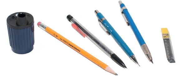
Acknowledgments and Copyright
Acknowledgments and Copyright
To learn more about BCcampus Open Textbook project, visit http://open.bccampus.ca
© Camosun College. The Trades Access Common Core resources are licensed under the Creative Commons Attribution 4.0
Unported Licence ( http://creativecommons.org/licenses/by/4.0/ ), except where otherwise noted. Under this licence, any user
of this textbook or the textbook contents herein must provide proper attribution as follows:
   If you redistribute this textbook in a digital format (including but not limited to EPUB, PDF, and HTML), then you must
   retain on every page the following attribution: Download for free at http://open.bccampus.ca/find-open-textbooks/
   If you redistribute this textbook in a print format, then you must include on every physical page the following attribution:
   Download for free at http://open.bccampus.ca/find-open-textbooks/
   If you redistribute part of this textbook, then you must retain in every digital format page view (including but not limited to
   EPUB, PDF, and HTML) and on every physical printed page the following attribution: Download for free at
   http://open.bccampus.ca/find-open-textbooks/
   If you use this textbook as a bibliographic reference, then you should cite it as follows: BCcampus, Name of Textbook or
   OER. DATE. http://open.bccampus.ca/find-open-textbooks/.
For questions regarding this licensing, please contact opentext@bccampus.ca
All images copyright BC Industry Training Authority are licensed under the Creative Commons Attribution-NonCommercial-
ShareAlike 4.0 licence.
http://creativecommons.org/licenses/by-nc-sa/4.0/
The issuing/publishing body is Crown Publications, Queen’s Printer, Ministry of Technology, Innovation and Citizens’
Services.
BCcampus would like to acknowledge the following individuals and organizations for their contributions in producing the
Trades Access Common Core Open Textbook resources.
BCcampus
Open Education Team
Hilda Anggraeni, Graphics
Camosun College
Olaf Nielsen, Chair, Trades Development and Special Projects, School of Trades and Technology
Nannette Plant, Manager, Enterprise Point Operations & Special Projects, Office of the VP Strategic Development
Rod Lidstone, Instructor, Plumbing and Pipe Trades, Lead Writer/Reviewer
Brian Coey, Instructor, Sheet Metal and Metal Fabrication, Writer/Reviewer
Matt Zeleny, Camosun Innovates, 3D imaging
Open School BC
Monique Brewer, Director
Adrian Hill, Instructional Designer
Dennis Evans, Image Coordinator, Photographer, Graphics, Production Technician (layout)
Farrah Patterson, Production Technician

5/7/2021                                                       1   CC-BY               https://workforce.libretexts.org/@go/page/3247
Foreword
Foreword
The BC Open Textbook Project began in 2012 with the goal of making post-secondary education in British Columbia more
accessible by reducing student cost through the use of openly licensed textbooks. The BC Open Textbook Project is
administered by BCcampus and is funded by the British Columbia Ministry of Advanced Education.
Open textbooks are open educational resources (OER); they are instructional resources created and shared in ways so that
more people have access to them. This is a different model than traditionally copyrighted materials. OER are defined as
teaching, learning, and research resources that reside in the public domain or have been released under an intellectual property
licence that permits their free use and repurposing by others (Hewlett Foundation). Our open textbooks are openly licensed
using a Creative Commons licence, and are offered in various e-book formats free of charge, or as printed books that are
available at cost. For more information about this project, please contact opentext@bccampus.ca. If you are an instructor who
is using this book for a course, please let us know.
Preface
The concept of identifying and creating resources for skills that are common to many trades has a long history in the Province
of British Columbia. This collection of Trades Access Common Core (TACC) resources was adapted from the 15 Trades
Common Core line modules co-published by the Industry Training and Apprenticeship Commission (ITAC) and the Centre for
Curriculum Transfer and Technology (C2T2) in 2000-2002. Those modules were revisions of the original Common Core
portion of the TRAC modules prepared by the Province of British Columbia Ministry of Post-Secondary Education in 1986.
The TACC resources are still in use by a number of trades programs today and, with the permission from the Industry Training
Authority (ITA), have been utilized in this project.
These open resources have been updated and realigned to match many of the line and competency titles found in the Province
of BC’s trades apprenticeship program outlines. A review was carried out to analyze the provincial program outlines of a
number of trades, with the intent of finding common entry-level learning tasks that could be assembled into this package. This
analysis provided the template for the outline used to update the existing modules. Many images found in ITA apprentice
training modules were also incorporated into these resources to create books that are similar to what students will see when
they continue their chosen trades training. The project team has also taken many new photographs for this project, which are
available for use in other trades training resources.
The following list of lines and competencies was generated with the goal of creating an entry-level trades training resource,
while still offering the flexibility for lines to be used as stand-alone books. This flexibility—in addition to the textbook content
being openly licensed—allows these resources to be used within other contexts as well. For example, instructors or institutions
may incorporate these resources into foundation-level trades training programming or within an online learning management
system (LMS).
Line A – Safe Work Practices
   A-1 Control Workplace Hazards
   A-2 Describe WorkSafeBC Regulations
   A-3 Handle Hazardous Materials Safely
   A-4 Describe Personal Safety Practices
   A-5 Describe Fire Safety
Line B – Employability Skills
   B-1 Apply Study and Learning Skills
   B-2 Describe Expectations and Responsibilities of Employers and Employees
   B-3 Use Interpersonal Communication Skills
   B-4 Describe the Apprenticeship System
Line C – Tools and Equipment
   C-1 Describe Common Hand Tools and Their Uses

5/21/2021                                                       1    CC-BY              https://workforce.libretexts.org/@go/page/3257

C-2 Describe Common Power Tools and Their Uses
   C-3 Describe Rigging and Hoisting Equipment
   C-4 Describe Ladders and Platforms
Line D – Organizational Skills
   D-1 Solve Trades Mathematical Problems
   D-2 Apply Science Concepts to Trades Applications
   D-3 Read Drawings and Specifications
   D-4 Use Codes, Regulations, and Standards
   D-5 Use Manufacturer and Supplier Documentation
   D-6 Plan Projects
Line E – Electrical Fundamentals
   E-1 Describe the Basic Principles of Electricity
   E-2 Identify Common Circuit Components and Their Symbols
   E-3 Explain Wiring Connections
   E-4 Use Multimeters
All of these textbooks are available in a variety of formats in addition to print:
   PDF—printable document with TOC and hyperlinks intact
   HTML—basic export of an HTML file and its assets, suitable for use in learning management systems
   Reflowable EPUB—format that is suitable for all screen sizes including phones
All of the self-test questions are also available from BCcampus as separate data, if instructors would like to use the questions
for online quizzes or competency testing.
About This Book
In an effort to make this book a flexible resource for trainers and learners, the following features are included:
   An introduction outlining the high-level goal of the Competency, and a list of objectives reflecting the skills and
   knowledge a person would need to achieve to fulfill this goal.
   Discrete Learning Tasks designed to help a person achieve these objectives
   Self-tests at the end of each Learning Task, designed to informally test for understanding.
   A reminder at the end of each Competency to complete a Competency test. Individual trainers are expected to determine
   the requirements for this test, as required.
   Throughout the textbook, there may also be links and/or references to other resources that learners will need to access,
   some of which are only available online.
   Notes, cautions, and warnings are identified by special symbols. A list of those symbols is provided below.

5/21/2021                                                        2    CC-BY             https://workforce.libretexts.org/@go/page/3257
Industry Training Authority of BC
Industry Training Authority of BC
The ITA works with employers, employees, industry, labour, training providers, and government to issue credentials, manage
apprenticeships, set program standards, and increase opportunities in approximately 100 BC trades. Among its many functions
are oversight of the development of training resources that align with program standards, outlines, and learning objectives, and
authorizing permission to utilize these resources (text and images).
Erin Johnston, Director of Training Delivery
Cory Williams, Manager, Industry Relations
Publishing Services, Queen’s Printer
Spencer Tickner, Director of QP Publishing Services
Dwayne Gordon, Manager, Electronic Publishing
October 2015, Version 1
To order print copies of any of the Trades Access Common Core resources, please contact us:
Crown Publications, Queen’s Printer
PO Box 9452 Stn Prov Govt
563 Superior St, 3rd Floor
Victoria, BC V8W 9V7
Phone: 250-387-6409
Toll Free: 1-800-663-6105
Fax: 250-387-1120
crownpub@gov.bc.ca
www.crownpub.bc.ca
Intellectual Property Program
Ilona Ugro, Copyright Officer, Ministry of Technology, Innovation and Citizens’ Services,
Province of British Columbia
Creative Commons Attributions
Cover photo:
(https://commons.wikimedia.org/wiki/File:DKR_Atelier.jpg) by DKR under CC BY SA 3.0
(https://creativecommons.org/licenses/by-sa/3.0/deed.en)

4/30/2021                                                     1    CC-BY              https://workforce.libretexts.org/@go/page/3256
Symbols Legend
Symbols Legend

                                                          Important:
                                          This icon highlights important information.

                                                           Poisonous:
                               This icon is a reminder for a potentially toxic/poisonous situation.

                                                          Resources:
                                The resource icon highlights any required or optional resources.

                                                          Flammable:
                                 This icon is a reminder for a potentially flammable situation.

                                                          Self-test:
                                         This icon reminds you to complete a self-test.

                                                          Explosive:
                                   This icon is a reminder for a possibly explosive situation.

                                                         Safety gear:
                          The safety gear icon is an important reminder to use protective equipment.

                                                        Electric shock:
                                      This icon is a reminder for potential electric shock.
Safety Advisory
Be advised that references to the Workers’ Compensation Board of British Columbia safety regulations contained within these
materials do not/may not reflect the most recent Occupational Health and Safety Regulation. The current Standards and
Regulation in BC can be obtained at the following website: http://www.worksafebc.com.
Please note that it is always the responsibility of any person using these materials to inform him/herself about the Occupational
Health and Safety Regulation pertaining to his/her area of work.
BCcampus
January 2015
Disclaimer
The materials in the Trades Access Common Core Open Textbook project are for use by students and instructional staff and
have been compiled from sources believed to be reliable and to represent best current opinions on these subjects. These
manuals are intended to serve as a starting point for good practices and may not specify all minimum legal standards. No
warranty, guarantee or representation is made by BCcampus as to the accuracy or sufficiency of the information contained in
these publications. These manuals are intended to provide basic guidelines for trade practices. Do not assume, therefore, that

4/30/2021                                                      1    CC-BY               https://workforce.libretexts.org/@go/page/3258
all necessary warnings and safety precautionary measures are contained in this module and that other or additional measures may not be required. 4/30/2021 2 CC-BY https://workforce.libretexts.org/@go/page/3258
CHAPTER OVERVIEW
1: DESCRIBE THE DRAFTING TOOLS AND MATERIALS USED IN DRAWING
PLANS
Traditionally, drafters sat at drafting boards and used pencils, pens, compasses, protractors, triangles,
and other drafting devices to prepare a drawing manually. Today, however, most professional
drafters use computer-aided drafting (CAD) systems to prepare drawings. Although drafters use
CAD extensively, it is only a tool. Drafters and tradespersons still need knowledge of traditional
drafting tools and techniques.
1.1: TOOLS
1.2: DRAFTING MATERIALS
1.3: COMPUTER DRAFTING PRINTING
1.E: SELF TEST 1
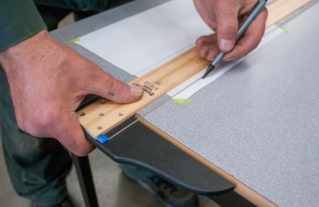
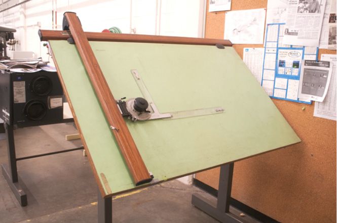
1 5/28/20211.1: Tools Tools Drafting tools are needed to lay out the different shapes and lines used to create drawings and sketches. A basic knowledge of the available tools and how to use them will assist you in your drawing. Drafting board or table The drafting board is an essential tool. Paper will be attached and kept straight and still, so the surface of the drafting board must be smooth and true, with no warps or twists. The surfaces of most drafting boards are covered with vinyl because it is smooth and even. The drafting board or table should have two parallel outside working edges made of either hardwood or steel. Most drafting table tops can be set at different heights from the floor and at any angle from vertical to horizontal. Other drafting tables may not have the same adjustments and may be limited to being raised only from horizontal to a low slope. To reduce back strain, use an adjustable drafting stool when working at a drafting table. Tables or boards should be a minimum of 1.2 m (4') in width and 0.9 m (3') in height. T-square The fixed head T-square is used for most work. It should be made of durable materials and have a transparent edge on the blade. To do accurate work, the blade must be perfectly square and straight; this should be checked regularly. The T-square is used to draw horizontal lines and to align other drawing instruments. If you are right-handed, you hold it tight against the left edge of the drawing board and move it up and down as required. When you make close adjustments, your fingers should be on top of the square and you should use your thumb to control the T-square’s movement (Figure 1). 1. Using a T-square 5/21/2021 1.1.1 CC-BY https://workforce.libretexts.org/@go/page/3226
2. Rabbeted edge

 3. Testing a triangle

 4. Drawing angles with one or two triangles

5/21/2021                                      1.1.2 CC-BY   https://workforce.libretexts.org/@go/page/3226
5. Protractor

 6. Drafting machine

 7. Wood and mechanical pencils

 8. Erasers and erasing shield

5/21/2021                         1.1.3 CC-BY   https://workforce.libretexts.org/@go/page/3226
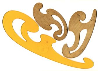
9. Templates

   10. French curve

5/21/2021             1.1.4 CC-BY   https://workforce.libretexts.org/@go/page/3226
1.2: Drafting Materials
Drafting materials
The most common support for drawing is paper. Even though the original creative surface has changed from the drafting table
to the computer screen, on the work site drawings are still primarily in printed form.
Drawing paper
There is a wide variety of drawing paper available in many sizes and of different qualities. Good quality drawing paper is acid-
free and will not turn yellow with age. Light-coloured drawing papers are available in pale yellow or buff, but these should be
used only when it is not necessary to make copies.
Tracing paper
Tracing paper, which is transparent, can be used to make copies of drawings. It is thin enough to allow the light of photocopy
machines to shine through the unmarked areas, and only the lines and figures will block the light. Materials used for tracing
include tracing paper, vellum, tracing cloth, glass cloth, and polyester film with a matte finish.
Standard paper sizes
Paper sizes typically comply with one of two different standards: ISO (world standard) or ANSI/ASME Y14 (American).
The standard ISO series of paper sizes is as follows:
A0 841 mm × 1189 mm
A1 594 mm × 841 mm
A2 420 mm × 594 mm
A3 297 mm × 420 mm
A4 210 mm × 297 mm
A5 148 mm × 210 mm
The standard ANSI/ASME series of paper sizes is as follows:
E 34 inch × 44 inch
D 22 inch × 34 inch
C 17 inch × 22 inch
B 11 inch × 17 inch
A 8.5 inch × 11 inch
The 81/2" × 11" standard letter paper corresponds to 216 mm × 279 mm. You can buy precut sheets that have a border and a
preprinted title block in the lower right-hand corner. These are available in many standard sizes.
If the paper you use does not have a border and title block, you will have to draw them in. The left-hand border should be
wider than the right-hand border and should be at least 50 mm wide to allow room for the prints to be bound. Figure 18 shows
a title block with suitable dimensions added.

4/30/2021                                                    1.2.1 CC-BY              https://workforce.libretexts.org/@go/page/3227
18. Dimensions for title block
   Paper rolls
   Many grades of paper rolls are available in different widths that can be cut to any length required.
   Drafting or masking tape
   Use drafting or masking tape to hold the paper on the drafting surface. The tape should be attached at the corners to hold
   the sheet firmly stretched with no wrinkles. Only short pieces of tape are required.

4/30/2021                                                    1.2.2 CC-BY               https://workforce.libretexts.org/@go/page/3227
1.3: Computer drafting printing
Computer drafting printing
Computer drafting programs are used effectively for all manner of drafting and have virtually replaced manual drafting. Small
size computer-generated drawings can be printed on normal computer printers. However, larger drawings require a plotter.
Older plotters used pencils, pens, or felt pens, but the new plotters are laser-based or jet printers and are capable of multiple
colours. They are made to print all the sizes of drawings. Plotters also print well on vellum and some other non-paper media.

                                          Now complete the Learning Task Self-Test.

4/23/2021                                                    1.3.1 CC-BY               https://workforce.libretexts.org/@go/page/3228
1.E: Self Test 1
Self-Test 1
1. What are most drafting tables covered with?
1. Vinyl
2. Wood
3. Metal
4. Plastic wrap
2. Drafting tables are adjustable in height and angle to the floor.
1. True
2. False
3. What are T-squares used for?
1. Drawing angled lines
2. Drawing vertical lines
3. Setting paper on a table
4. Drawing horizontal lines
4. Why might a set square have rabbeted edges?
1. To help you prevent smudges
2. To help keep your pencil sharp
3. To help keep your pencil aligned
4. To allow you to draw straight lines
5. Checking a triangle should be done periodically.
1. True
2. False
6. What is a set square used for?
1. Drawing circles
2. Drawing curved lines
3. Drawing vertical and angled lines
4. Drawing horizontal and angled lines
7. When using a 45°-90°-45° and a 30°-60°-90° triangle, angles can be drawn every 10°.
1. True
2. False
8. What is a protractor used for?
1. Measuring lines
2. Measuring angles
3. Drawing angled lines
4. Drawing straight lines
9. What kind of line is drawn to check a triangle?
1. Straight
2. Parallel
3. Oblique
4. Perpendicular
10. What is a compass used for?
1. Drawing angled lines
2. Drawing straight lines
3. Drawing arcs and circles
4. Drawing irregular curves
5/7/2021 1.E.1 CC-BY https://workforce.libretexts.org/@go/page/322911. What is an erasing shield used for?
1. To erase mistakes
2. To hold the eraser
3. To erase in a desired area
4. To prevent the need for erasing
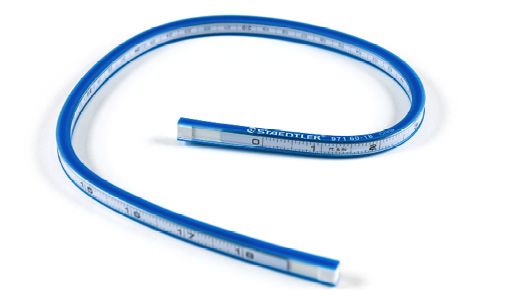
12. A spline is a plastic or rubber rod reinforced with metal used for drawing curves.
1. True
2. False
13. What is the tool called a divider used for?
1. Drawing circles
2. Drawing a diameter
3. Scribing arcs on metal
4. Drawing arcs and curves
14. What is the purpose of a scale ruler?
1. To draw straight lines
2. To enlarge the scale of a drawing
3. To create drawings at a reduced scale
4. To convert between imperial and metric measures
5/7/2021 1.E.2 CC-BY https://workforce.libretexts.org/@go/page/3229CHAPTER OVERVIEW
2: DESCRIBE LINES, LETTERING, AND DIMENSIONING IN DRAWINGS
2.1: LINE STYLES AND TYPES
2.2: STANDARD LETTERING
2.3: PRINCIPLES OF DIMENSIONING
2.E: SELF-TEST 2
1 5/28/20212.1: Line styles and types Learning Task 2 Describe lines, lettering, and dimensioning in drawings The purpose of engineering drawings is to convey objective facts, whereas artistic drawings convey emotion or artistic sensitivity in some way. Engineering drawings and sketches need to display simplicity and uniformity, and they must be executed with speed. Engineering drawing has evolved into a language that uses an extensive set of conventions to convey information very precisely, with very little ambiguity. Standardization is also very important, as it aids internationalization; that is, people from different countries who speak different languages can read the same engineering drawing and interpret it the same way. To that end, drawings should be as free of notes and abbreviations as possible so that the meaning is conveyed graphically. Line styles and types Standard lines have been developed so that every drawing or sketch conveys the same meaning to everyone. In order to convey that meaning, the lines used in technical drawings have both a definite pattern and a definite thickness. Some lines are complete and others are broken. Some lines are thick and others are thin. A visible line, for example, is used to show the edges (or “outline”) of an object and to make it stand out for easy reading. This line is made thick and dark. On the other hand, a centre line, which locates the precise centre of a hole or shaft, is drawn thin and made with long and short dashes. This makes it easily distinguishable from the visible line. When you draw, use a fairly sharp pencil of the correct grade and try to maintain an even, consistent pressure to make it easier for you to produce acceptable lines (Figure 1). Study the line thicknesses (or “line weights”) shown in Figure 2 and practise making them. 1. Lead grade and usage 5/14/2021 2.1.1 CC-BY https://workforce.libretexts.org/@go/page/3230
Curled lines to abbreviate a longer span of pipe.
 2. Weights of lines

 3. Object lines

 4. Hidden lines

 5. Centre lines

 6. Dimension and extension lines

5/14/2021                                              2.1.2 CC-BY   https://workforce.libretexts.org/@go/page/3230
7. Leader lines

 8. Phantom lines

 9. Cutting plane lines

5/14/2021                 2.1.3 CC-BY   https://workforce.libretexts.org/@go/page/3230
10. Section lines combined with cutting plane lines

11. Break line

5/14/2021                                             2.1.4 CC-BY   https://workforce.libretexts.org/@go/page/3230
2.2: Standard lettering
Standard lettering
The letters and numbers on a drawing or sketch are as important as the lines. Scribbled, smudged, or badly written letters and
numbers can become impossible to read. This may lead to time-consuming and costly errors. Lettering is necessary to
describe:
   the name or title of a drawing
   when it was made
   the scale
   who sketched it
   the dimensions
   the special notations that describe the size
   the materials to be used
   the construction methods
The American Standard Vertical letters (Figure 12) have become the most accepted style of lettering used in the production of
manual drafting. This lettering is a Gothic sans serif script, formed by a series of short strokes.
Font styles and sizes may vary in computer drafting. Note that all letters are written as capital (upper case) letters. Practise
these characters, concentrating on forming the correct shape. Remember that letters and numbers must be black so that they
will stand out and be easy to read. Lettering and figures should have the same weight and darkness as hidden lines.

12. Standard lettering

4/30/2021                                                    2.2.1 CC-BY              https://workforce.libretexts.org/@go/page/3231
13. Standard lettering sizes

4/30/2021                      2.2.2 CC-BY   https://workforce.libretexts.org/@go/page/3231
2.3: Principles of Dimensioning
Principles of dimensioning
A good sketch of an object is one that you can use as a blueprint to manufacture the object. Your sketch must show all the
necessary dimensions of the part, locate any features it may have (such as holes and slots), give information on the material it
is to be made from, and if necessary, stipulate the processes to be used in the manufacture of the object.
Three principles of dimensioning must be followed:
 1. Do not leave any size, shape, or material in doubt.
 2. To avoid confusion and the possibility of error, no dimension should be repeated twice on any sketch or drawing.
 3. Dimensions and notations must be placed on the sketch where they can be clearly and easily read.
Consider Figure 14 and note whether these three dimensioning principles have been followed.

14. Shop table

5/7/2021                                                     2.3.1 CC-BY              https://workforce.libretexts.org/@go/page/3232
15. Dimensioning

16. Shim plate

5/7/2021           2.3.2 CC-BY   https://workforce.libretexts.org/@go/page/3232
17. Extension line usage

18. Dimensioning systems

19. Connector arm – metric measurement

5/7/2021                                 2.3.3 CC-BY   https://workforce.libretexts.org/@go/page/3232
20. Connector arm – imperial measurement

21. Fuel storage shed

                                           Now complete the Learning Task Self-Test.

5/7/2021                                                   2.3.4 CC-BY            https://workforce.libretexts.org/@go/page/3232
2.E: Self-Test 2
Self-Test 2
1. Which line in a drawing should be the darkest and thickest?
1. Centre line
2. Hidden line
3. Object line
4. Dimension line
2. This line in a drawing is a broken line of alternating short and long dashes.
1. Centre line
2. Hidden line
3. Phantom line
4. Compression line
3. What is the name of a line in a drawing that shows a hidden feature?
1. Buried line
2. Missing line
3. Hidden line
4. Concealed line
4. A break line shows where part of an object in a drawing has been removed.
1. True
2. False
5. A drawing should have all dimensions shown in every view.
1. True
2. False
6. Which line is used to shows notes or specifications in a drawing?
1. Leader line
2. Object line
3. Extension line
4. Phantom line
7. How are alternate positions of moving parts shown in a drawing?
1. With a break line
2. With a hidden line
3. With an object line
4. With a phantom line
8. What does a sectional view in a drawing normally show?
1. Outside of a part
2. Inside dimensions
3. Internal holes and slots
4. Internal features of a part
9. What do the arrows that locate a sectional view in a drawing indicate?
1. Side the part is cut on
2. Internal holes and slots
3. Direction of the standard view
4. Direction of observation when the section is drawn
10. In the drawing below, indicate whether the dimensions shown by letters D2 and D4 are size dimensions, no dimensions,
location dimensions, or notation dimensions.
1. Size dimensions
5/28/2021 2.E.1 CC-BY https://workforce.libretexts.org/@go/page/32332. No dimensions
3. Notation dimensions
4. Location dimensions
5/28/2021 2.E.2 CC-BY https://workforce.libretexts.org/@go/page/3233CHAPTER OVERVIEW
3: USE SCALE RULERS TO DETERMINE ACTUAL DIMENSIONS FROM
DRAWINGS
3.0: PRELUDE TO SCALES
3.2: METRIC SCALES
3.3: OBTAIN DIMENSIONS FROM DRAWINGS
3.E: SELF TEST 3
UNTITLED PAGE 19
1 5/28/20213.0: Prelude to Scales
Learning Task 3
Use scale rulers to determine actual dimensions from drawings
Scale drawings are accurate and convenient visual representations made and used by engineers, architects, and people in the
construction trades. The accuracy is achieved because the drawing is proportional to the real thing. The convenience comes
from the size of the drawing. It is large enough to provide the desired detail but small enough to be handy.
The flexibility to draw proportionally in different sizes is provided by scales. For the purposes of representation, we will only
be concerned with reduction scales. Reduction scales make the drawing smaller than the object. The kinds of rulers we will be
discussing for making scaled drawings are the architect’s scale and the metric scale, both shown in Figure 1.
Architect's scale ruler
Metric scale ruler
1. Architect’s and metric rulers
The scale of the drawing is always written on the drawing, unless the drawing is not drawn to scale. In the latter case, this
will be indicated by the “not to scale” abbreviation (NTS). The scale is the ratio of the size of the drawing to the object. For
drawings smaller than the object, the ratio is that of a smaller distance to a larger one.
The architect’s scales use ratios of inches to a foot. The most common architect’s scale used is 1/4 inch to the foot, written
on drawings as:
Scale 1/4" = 1'-0"
This means that a line 1/4" long on the drawing represents an object that is one foot long. At the same scale, a line 1½"
long represents an object 6' long, because 1½" contains 6 quarter-inches.
Metric scale ratios use the same units in both ratio terms, resulting in an expression of how many times smaller than the
object the drawing is. For example, the standard metric scale ratio that corresponds approximately to ¼" = 1'-0" is written
on drawings as "Scale 1:50."
This means that the object is 50 times as large as the drawing, so that 50 mm on the object is represented by 1 mm on the
drawing. For another example, 30 mm on the drawing represents 50 × 30 mm = 1500 mm (or 1.5 metres) on the object.
Figure 2 lists the scale ratios used for building plans and construction drawings in both metric and the approximate
equivalent architectural scale ratios.
Type of Drawing Common Metric Ratios Imperial Equivalents and Ratios Use
To locate the building,
1:500 1" = 40'-0" 1:480
Site plan services and reference
1:200 1/16" =1'-0" 1:192
points on the site
Sketch plans 1:200 1/16" =1'-0" 1:192 To show the overall
General locations 1:100 1/8" =1'-0" 1:96 design of the building
To indicate the
juxtaposition of the
4/23/2021 3.0.1 CC-BY https://workforce.libretexts.org/@go/page/3234Type of Drawing Common Metric Ratios Imperial Equivalents and Ratios Use
rooms and locate the
positions of piping
Drawings 1:50 1/4" =1'-0" 1:48 systems and
components
1:20 1/2" =1'-0" 1:24
To show the detail of
1:10 1" = 1'-0" 1:12
Construction details system components
1:5 3" =1'-0" 1:4
and assemblies
1:1 Full size 1:1
2. Preferred scales for building drawings
4/23/2021 3.0.2 CC-BY https://workforce.libretexts.org/@go/page/32343.2: Metric Scales
A triangular metric scale is similar to the architectural scale in that it has six edges, but it has only one scale ratio per edge.
The ratio is marked at the left end of the scale. For example, the scale of 1:50 means that 1 mm on the drawing represents 50
mm on the object. This means that the object is 50 times larger than the drawing of it. An object 450 mm long would be
represented by a line 9 mm long (450 mm/50).
Figure 7 shows one of the three sides of a metric scale. The scale labelled 1:50 is read from left to right, from 0 to 15 m. The
1:5 scale (on the bottom) can also be read from left to right (0 to 600 mm) by turning the scale around.
7. One side of a metric ruler
The ratios most often used in drawings are 1:100 for larger buildings, 1:50 for smaller buildings, and 1:20 for details.
8. Metric scales marked at 250 mm
The length of an object represented on a drawing in a metric scale is found by measuring the drawn object with a metric
ruler of the proper scale. You can also measure the drawing with any metric tape measure and multiply that by the scale
ratio.
4/23/2021 3.2.1 CC-BY https://workforce.libretexts.org/@go/page/32373.3: Obtain dimensions from drawings
The best way to get exact dimensions from drawings is to use the explicit dimensions (in millimeters or in feet and inches)
written between the dimension lines. Any measurements that you need should be somewhere on the drawings. Drawings
normally only give each dimension once. If there are a number of parallel lengths, only one will have a measurement. To find
the dimension you need, you may need to refer to other views or you may have to add or subtract other dimensions.
Measuring lines on a drawing to determine the measurement is not an accurate way to extract dimensions. This is because the
drawing is only a representation and may not be exact. Photocopies of drawings may not be to the scale of the original.
The scale of the drawing and your accuracy in measuring will lead to inaccuracies. For example, if the scale of a drawing is
1/8" = 1'-0", an error of 1/32" in measuring the plan amounts to 3" of error in the object measured. Detail drawings permit
more exactness because they are proportionately larger. Details, however, often require more exactness and usually contain
any needed dimensions.
When accuracy is not required and approximate dimensions are adequate, measuring plans is a quick method of taking off
material for estimating the cost of a job. In such cases, 10% is usually added for cut-off and waste allowance.
Measuring plans is not accurate enough for measuring materials for cutting and installation purposes.
If you use the scale of the drawing, it will be simple to read off the measurements. However, in the field you will often need
approximate measurements and the only measuring tool at hand will be a measuring tape.
A steel pocket tape measure has a movable hook on the end that allows accurate measuring both when butted against a surface
or when hooked on the end of an object (Figure 9). The end of the flexible tape itself is shortened to allow for the hook.
9. Tape measure with movable hook
10. Measuring metric drawings
The reciprocals of all standard scales used by architects are shown in Figure 11.
5/14/2021 3.3.1 CC-BY https://workforce.libretexts.org/@go/page/3238Scale 3/32 1/8 3/16 1/4 3/8 1/2 3/4 1 1 1/2 (3/2) 3
Reciprocal 32/3 8 16/3 4 8/3 2 4/3 1 2/3 1/3
11. Reciprocals of standard scales
12. Reading lengths of piping runs
Now complete the Learning Task Self-Test.
5/14/2021 3.3.2 CC-BY https://workforce.libretexts.org/@go/page/32383.E: Self Test 3
Self-Test 3
1. Scale rulers are available in both imperial and metric.
1. True
2. False
2. Which scale ruler would be most likely to have a ¼" to 1' scale on it?
1. Metric scale ruler
2. Architect’s scale ruler
3. Civil engineer’s scale ruler
4. Mechanical engineer’s scale ruler
3. How many scale ratios per edge do metric scale rulers have?
1. 1
2. 2
3. 3
4. 4
4. What is the best way to get exact dimensions from a drawing?
1. Measure using a tape measure.
2. Exact dimensions aren’t important.
3. Scale it with your combination square.
4. Use the dimension written between the dimension lines.
5. If a line measures 4½", what is the equivalent in 1/4"=1' scale?
1. 9"
2. 18'
3. 9'
4. 18"
6. If a line measures 63/8", what is the equivalent in 1/8" = 1' scale?
1. 27"
2. 48'
3. 4'3"
4. 51'
7. What is the measurement of the line below?
1. 68'
2. 6'3"
3. 80'
4. 12'6"
8. What is the measurement of the line below?
4/30/2021 3.E.1 CC-BY https://workforce.libretexts.org/@go/page/32391. 1'3"
2. 1'6"
3. 27'3"
4. 27'6"
9. What is the measurement of the line below?
1. 16'2"
2. 16'4"
3. 16'6"
4. 16'9"
10. What is the measurement of the line below?
1. 3'4"
2. 3'7"
3. 9'4"
4. 13'7"
11. What is the measurement of the line below?
1. 35 mm
2. 3.5 m
3. 35 m
4. 350 m
12. What is the measurement of the line below?
1. 0.19 m
2. 1.9 m
3. 19 m
4/30/2021 3.E.2 CC-BY https://workforce.libretexts.org/@go/page/32394. 190 m
13. What is the measurement of the piping run below in 1/2"=1' scale?
1. 8'6"
2. 10'6"
3. 17'
4. 34'
4/30/2021 3.E.3 CC-BY https://workforce.libretexts.org/@go/page/3239Untitled Page 19 Architect’s (imperial) scales Traditional architectural measurements of length are written very precisely in feet and inches using the appropriate symbols for feet and inches separated by a dash (e.g., 4'-3 ½" and 7'-0"). This is the way that all imperial measurements are written on construction drawings. Listed below are the scales found on the architect’s triangular scale ruler. 1. 3/32" =1'-0" 2. 3/16" = 1'-0" 3. 1/8" = 1'-0" 4. ¼" = 1'-0" 5. ¾" = 1'-0" 6. 3/8" = 1'-0" 7. 1" =1'-0" 8. ½" = 1'-0" 9. 1½" = 1'-0" 10. 3" = 1'-0" 11. 1" = 1" (full size—use the scale labelled 16) Figure 3 shows one face of an architect’s imperial triangular scale ruler. There are two edges on each face and each edge contains two scales that run in opposite directions. At each end of an edge, a number or fraction indicates the distance in inches that represents one foot. The top edge is in eighths of an inch from left to right, and in quarters of an inch from right to left. Note that the 1/8" scale from 0 to the right end represents 95 feet, and the ¼" scale from 0 to the left end represents 47 feet. 3. One face of an architect’s ruler (NTS) 4. Units in an architect’s scale ruler (NTS) 5/21/2021 1 CC-BY https://workforce.libretexts.org/@go/page/3235
5. Reading dimensions using an architect’s ruler (NTS)

 6. Reading dimensions using an architect’s ruler (NTS)

   Architectural units have feet divided into inches, whereas engineering units divide feet into tenths and hundredths.
   Engineers’ scales are not used to make piping drawings.

5/21/2021                                                 2   CC-BY             https://workforce.libretexts.org/@go/page/3235
CHAPTER OVERVIEW
4: DESCRIBE DRAWING PROJECTIONS
Architectural drawings are made according to a set of conventions, which include particular views
(floor plan, section, etc.), sheet sizes, units of measurement and scales, annotation, and cross-
referencing.

 4.1: TYPES OF VIEWS USED IN DRAWINGS
 4.E: SELF TEST 4

                                                                 1                                  5/28/2021
4.1: Types of views used in drawings Types of views used in drawings The two main types of views (or “projections”) used in drawings are: pictorial orthographic Pictorial views Pictorial views show a 3-D view of how something should look when completed. There are three types of pictorial views: perspective isometric oblique Perspective view A perspective view presents a building or an object just as it would look to you. A perspective view has a vanishing point; that is, lines that move away from you come together in the distance. For example, in Figure 1, we see a road and line of telephone poles. Even though the poles get smaller in their actual measurement, we recognize them as being the same size but more distant. 1. Perspective view 2. An isometric view 5/7/2021 4.1.1 CC-BY https://workforce.libretexts.org/@go/page/3241
3. Oblique view of the object in Figure 2

 4. Multi-view through a glass box

 5. Box opened to produce orthographic views

5/7/2021                                       4.1.2 CC-BY   https://workforce.libretexts.org/@go/page/3241
6. Drawing with the glass box flattened out

 7. Orthographic views of the object in Figure 2

5/7/2021                                           4.1.3 CC-BY   https://workforce.libretexts.org/@go/page/3241
8. Main floor plan of a house

 9. Left elevation of house in Figure 8

5/7/2021                                  4.1.4 CC-BY   https://workforce.libretexts.org/@go/page/3241
10. Section A-A

5/7/2021          4.1.5 CC-BY   https://workforce.libretexts.org/@go/page/3241
11. Section A-A

                  Now complete the Learning Task Self-Test.

5/7/2021                          4.1.6 CC-BY            https://workforce.libretexts.org/@go/page/3241
4.E: Self Test 4
Self-Test 4
1. A perspective drawing is one form of which type of view?
1. Oblique
2. Pictorial
3. Isometric
4. Orthographic
2. At what angle should isometric drawings have horizontal lines drawn?
1. 15°
2. 30°
3. 45°
4. 60°
3. What do perspective drawings always have?
1. Scale
2. Dimensions
3. Hidden lines
4. Vanishing points
4. At what angles should oblique drawings have lines drawn?
1. 0°–15°
2. 15°–30°
3. 30°–45°
4. 45°–60°
5. Orthographic projection drawings are three-dimensional drawings.
1. True
2. False
6. What is a common name for a top view in an orthographic drawing?
1. Plan view
2. Down view
3. Ceiling view
4. Elevation view
7. In orthographic projection, how many views are most commonly shown?
1. 1
2. 2
3. 3
4. 4
8. In the diagrams below, match letters A to L with numbers 1 to 12.
5/7/2021 4.E.1 CC-BY https://workforce.libretexts.org/@go/page/32429. What is a top view called in a construction drawing?
1. Plan view
2. Floor plan
3. Floor detail
4. Building plan
10. What are drawings called that show door and window locations, and other exterior finishes of a building?
1. Wall drawings
2. Front drawings
3. Exterior drawings
4. Elevation drawings
5/7/2021 4.E.2 CC-BY https://workforce.libretexts.org/@go/page/3242CHAPTER OVERVIEW
5: INTERPRET MECHANICAL DRAWINGS
Interpreting drawings requires the ability to visualize and the ability to interpret what is being drawn
and written. The drawing should be studied carefully before beginning any work. The reader should
attempt to visualize what is being shown on the drawing and how it will be built. Mistakes can be
made when the tradesperson does not take the time to become fully familiar with the drawing.
5.1: BASIC LAYOUT OF A DRAWING
5.2: SPECIFICATIONS
5.E: SELF-TEST 5
1 5/28/20215.1: Basic layout of a drawing
Basic layout of a drawing
The layout of most drawings is similar in that the drawing format has some standard features or components. A typical
drawing format will include some or all of these features:
title block
bill of materials or material list
area where the job specifications are listed
general notes
reference drawing list
revision chart
These drawing components are common for some types of drawings; however, other components may be used to show the
necessary information for the complete design.
Each of the listed drawing components serves a specific purpose and contains information about the job and its specifications
(Figure 1).
1. Drawing format
The following information is a guideline to use each time a new drawing is observed.
Title block
The title block is located in the lower right corner of the drawing and is separated from the main drawing. The contents of
the title block will vary from company to company and often differ from drawing to drawing by the same company. As a
standard feature, a company will have its name and logo in the title block along with other standard company information,
plus particular information such as the customer’s name.
The following information can be located in the title block; however, note that not all of the items listed below are
necessarily included:
job title
name of the item to be fabricated or installed
name of the customer
name of the designing engineer or firm
name or initial of draftsperson and checker
date drawn
drawing number
5/14/2021 5.1.1 CC-BY https://workforce.libretexts.org/@go/page/3244contract number or job number
number of revisions, if any, for the drawings
scale of the drawing
Bill of materials
The bill of materials is usually located in the upper right corner of the drawings, above the title block. As with the title
block, the bill of materials is separated from the rest of the drawing and is essentially a table with partitioned rows and
columns showing:
item number or mark number
quantity
material description
material grade
material weight
remarks
Revision chart
The revision chart is often located to the left of the title block and is bordered off from the rest of the drawing. The revision
chart, like the bill of materials, is divided into rows and columns. These columns identify the revision number and give a
general description of the revision, who checked the revision, and the date of the revision. It is important to make sure that
you are working from the latest revision, as it is not uncommon for changes to be made from the original drawing.
Drawing specifications
The specifications section of a drawing is used to list all the design information of the item being built or installed. This
section is often located to the left of the revision chart. If drawing space is a problem, it may be located elsewhere. A
common location is the area below the bill of materials. (The contents of specifications are covered in more detail later.)
Drawing notes
Drawings will often contain two types of notes: general and specific. The general and specific notes should not be confused
with the information found in the bill of materials, title block, revision chart, or the drawing specifications.
The general notes are usually located in the upper left corner of the drawing. A general note is information about the
fabrication that refers to similar items or procedures throughout the drawing. Specific notes can be found anywhere on the
drawing as needed and are most often written with a leader line pointing to the relevant part or area.
Reference drawings
A job requiring more than one drawing is called a drawing set, and it contains two or more drawings. It is a common
practice to have a list of all of the drawings that make up the drawing set. This listing is referred to as the reference
drawings for the project.
Often work being shown on one drawing requires you to look at or reference other drawings in the set. There is no specific
area where the reference drawings are listed; however, two common locations are near the bottom of the print on the far
left-hand side, and just below the bill of materials.
5/14/2021 5.1.2 CC-BY https://workforce.libretexts.org/@go/page/32445.2: Specifications
Specifications
Specifications in North America form part of the contract documents that accompany and govern the construction of a
building. Specifications are written descriptions of the materials and procedures that must be used in constructing a building or
system.
These specifications translate working drawings into words to ensure that systems will be neither overdesigned nor
underdesigned. They tell the contractor exactly which materials must be used.
Aside from serving as a manual on how to do the job, the book of specifications has another function: it is a legal document
outlining each contractor’s obligations. These obligations may include the need to provide fire insurance, to pay for municipal
inspections, or to complete the job by a certain deadline.
Specifications are divided into 50 divisions of construction information as defined by the Construction Specifications
Institute’s (CSI’s) MasterFormat. Before 2004, MasterFormat consisted of 16 divisions. MasterFormat is the most widely used
standard for organizing specifications and other written information for commercial and institutional building projects in the
United States and Canada. It provides a master list of divisions, and section numbers and titles within each division, to follow
in organizing information about a facility’s construction requirements and associated activities. Standardizing the presentation
of such information improves communication among all parties involved in construction projects.
For more information about the 50 CSI divisions, go to:
http://en.Wikipedia.org/wiki/MasterFormat
Now complete the Learning Task Self-Test.
4/30/2021 5.2.1 CC-BY https://workforce.libretexts.org/@go/page/32455.E: Self-Test 5
Self-Test 5
1. Where is the scale of a drawing found?
1. In the revisions
2. In the title block
3. In the specifications
4. In the bill of materials
2. The specifications of a drawing serve as a legal contract for the job.
1. True
2. False
3. Where on a drawing would information on material grade be found?
1. In the title block
2. In the specifications
3. In the revision chart
4. In the bill of materials
4. Specifications are a written description of a construction project.
1. True
2. False
5. What should the title block on a drawing always include?
1. Title
2. Date
3. Name of the draftsperson
4. All of the above
4/30/2021 5.E.1 CC-BY https://workforce.libretexts.org/@go/page/3246CHAPTER OVERVIEW
6: CREATING DRAWINGS AND SKETCHES
Freehand sketching is a very useful skill that can be mastered with practice and by following a few
guidelines. The ability to interpret drawings is complemented by the ability to sketch information
from a drawing to take to your work location. Sketching is also a valuable tool when no drawing is
available and you need to communicate job information to someone else. For freehand sketching,
you require a pad of graph paper (8 ½" × 11" sheets with a 5 mm or ¼" grid), a sharp HB pencil, and
an eraser. Do not begin any sketch with a dull pencil.
6.1: SKETCHING TECHNIQUE
6.2: MAKE ISOMETRIC SKETCHES OF SIMPLE RECTANGULAR OBJECTS
6.3: SKETCHING FIGURES WITH NON-ISOMETRIC LINES
1 5/28/20216.1: Sketching Technique Sketching technique Sketching provides a quick and simple way to express ideas and to communicate the shape and general size of an object. Sketching parallel lines Start by drawing lines that are parallel to the edges of the paper, such as a border line and title block. Use your finger as a guide when you draw along the grid line on the sketch pad (Figure 1). If you let the end of your little finger run down the edge of the paper pad as you draw, this will steady your hand and make it easier to get a straight line. 1. Sketching a parallel vertical line 2. Sketching a horizontal line 4/30/2021 6.1.1 CC-BY https://workforce.libretexts.org/@go/page/3249
3. Sketching a rectangle

 4. Sketching a circle

 5. Sketching to scale

4/30/2021                   6.1.2 CC-BY   https://workforce.libretexts.org/@go/page/3249
6. Full-size isometric object

 7. Scale orthographic projections

4/30/2021                            6.1.3 CC-BY   https://workforce.libretexts.org/@go/page/3249
6.2: Make isometric sketches of simple rectangular objects
Make isometric sketches of simple rectangular objects
Isometric sketches are useful because they are easy to draw and clearly represent an object or system. This clarity comes from
using directional lines to represent the three dimensions of length, width, and height, much like a picture.
Construction methods
The following steps explain how to draw an isometric cube. The three dimensions of length, width, and height are drawn along
the isometric axes shown in Figure 8. The lengths of objects running parallel to these axes can be drawn to scale. Lines at
other angles will not be to scale.

 8. Isometric axes

 9. Step 1: Isometric guide for front-right view

10. Step 2: Isometric view of top surface of a rectangular block

5/21/2021                                                    6.2.1 CC-BY            https://workforce.libretexts.org/@go/page/3250
11. Step 3: Lines parallel to L and D

12. Step 4: Completed outline of rectangular block

13. Completed isometric sketch

5/21/2021                                            6.2.2 CC-BY   https://workforce.libretexts.org/@go/page/3250
You can also read