Hughes 9450 Series User Guide - Hughes Network Systems
←
→
Page content transcription
If your browser does not render page correctly, please read the page content below
Hughes 9450 Series
User Guide

H64159
Revision A
27 December 2019
Copyright © 2011 - 2019 Hughes Network Systems, LLC
All rights reserved. This publication and its contents are proprietary to Hughes Network
Systems, LLC. No part of this publication may be reproduced in any form or by any means
without the written permission of Hughes Network Systems, LLC, 11717 Exploration Lane,
Germantown, Maryland 20876.
Hughes Network Systems, LLC has made every effort to ensure the correctness and
completeness of the material in this document. Hughes Network Systems, LLC shall not
be liable for errors contained herein. The information in this document is subject to change
without notice. Hughes Network Systems, LLC makes no warranty of any kind with regard
to this material, including, but not limited to, the implied warranties of merchantability and
fitness for a particular purpose.

                                      Trademarks
Hughes and Hughes Network Systems are trademarks of Hughes Network Systems, LLC.
All other trademarks are the property of their respective owners.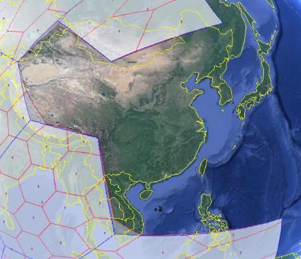
Contents
Understanding safety alert messages ..................................................................................... v
Messages concerning personal injury .................................................................................................... v
Messages concerning property damage ................................................................................................. v
Safety symbols ....................................................................................................................... vi
Introduction............................................................................................................................ 1
Overview ............................................................................................................................................. 1
9450 Variants ....................................................................................................................................... 2
About this User Guide .......................................................................................................................... 3
Package Contents ................................................................................................................................. 3
Minimum System Requirements for Laptop/PC .................................................................................... 3
Getting Started ..................................................................................................................................... 4
Installing your terminal ........................................................................................................................ 4
Terminal LED functionality .................................................................................................................. 4
Using the Hughes 9450 ........................................................................................................... 6
Auto start configuration ........................................................................................................................ 6
Power up and the connection to the Internet .......................................................................................... 7
Connecting the terminal to the computer ............................................................................................... 7
  Connecting by Ethernet..................................................................................................................... 8
  Power over Ethernet (POE)............................................................................................................... 8
  Connecting by WLAN ...................................................................................................................... 8
    WLAN Security ............................................................................................................................ 9
  Connecting by ISDN......................................................................................................................... 9
  Connecting by RJ11........................................................................................................................ 10
Coverage Map .................................................................................................................................... 11
  Operation in the MEAS cutout area................................................................................................. 12
  Operation in the Russian Federation ................................................................................................ 13
Using the Web UI ................................................................................................................. 14
Accessing the Web UI ........................................................................................................................ 14
Home page ......................................................................................................................................... 16
Connections ....................................................................................................................................... 19
  Manage Connections ...................................................................................................................... 19
  Automatic Contexts ........................................................................................................................ 20
  Manage APNs ................................................................................................................................ 25
SMS ................................................................................................................................................... 27
  Send/Receive .................................................................................................................................. 27
  Saved Drafts ................................................................................................................................... 28

                                                                                                                             • Contents                      iii
                                                                                                                      H64159 Revision A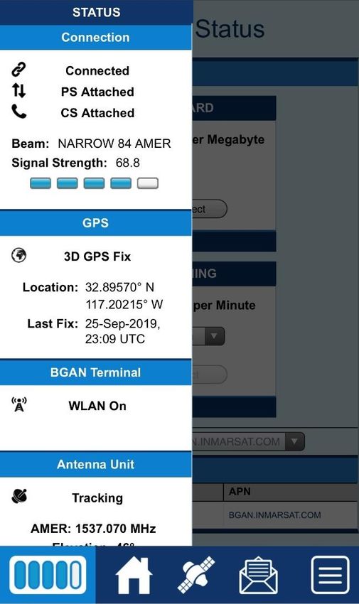
Sent Messages ................................................................................................................................ 28
   SMS Settings .................................................................................................................................. 29
 Settings page ...................................................................................................................................... 31
   General Setup ................................................................................................................................. 31
   IP Address/DHCP Settings ............................................................................................................. 33
      Nat Mode.................................................................................................................................... 35
      NAPT Mode ............................................................................................................................... 35
      Relay Mode ................................................................................................................................ 35
   Port Forwarding Page ..................................................................................................................... 36
   Wireless LAN................................................................................................................................. 37
   Wireless LAN Security ................................................................................................................... 40
   Telephony ...................................................................................................................................... 42
   Security .......................................................................................................................................... 44
   Features .......................................................................................................................................... 46
 M2M Page ......................................................................................................................................... 48
      Ping Configuration:..................................................................................................................... 48
      Always On Context:.................................................................................................................... 48
 Usage Page......................................................................................................................................... 50
 Support Page ...................................................................................................................................... 51
 Smart Phone Web UI .......................................................................................................................... 54
 Troubleshooting ................................................................................................................... 56
     PDP Context Activation Errors ....................................................................................................... 56
 Technology Overview ........................................................................................................... 59
 GPS.................................................................................................................................................... 59
   Obtaining a GPS Fix ....................................................................................................................... 59
   GPS and BGAN Registration .......................................................................................................... 60
 ISDN.................................................................................................................................................. 60
   Dialing and Numbering................................................................................................................... 60
 PDP Context ...................................................................................................................................... 60
 Technical Specifications ....................................................................................................... 62
 Regulatory Notices ............................................................................................................... 63
 EU Declaration of Conformity ............................................................................................................ 63
 FCC Compliance ................................................................................................................................ 63
 EU WEEE (Waste Electrical and Electronic Equipment) Directives .................................................... 63
 Glossary ................................................................................................................................ 64

iv           • Contents
             H64159 Revision A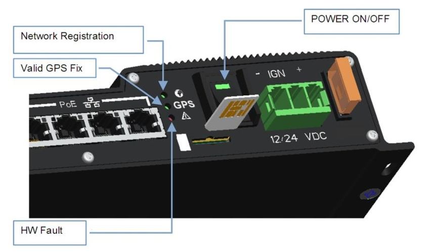
Understanding safety alert messages
                      Safety alert messages call attention to potential safety hazards
                      and tell you how to avoid them. These messages are identified
                      by the signal words DANGER, WARNING, CAUTION, or
                      NOTICE, as illustrated below. To avoid possible property
                      damage, personal injury, or in some cases possible death read
                      and comply with all safety alert messages.

Messages concerning
personal injury
                      The signal words DANGER, WARNING, and CAUTION
                      indicate hazards that could result in personal injury or in some
                      cases death, as explained below. Each of these signal words
                      indicates the severity of the potential hazard.

                      DANGER indicates a potentially hazardous situation which, if
                      not avoided, will result in death or serious injury

                      WARNING indicates a potentially hazardous situation which, if
                      not avoided, could result in death or serious injury.

                      CAUTION indicates a potentially hazardous situation which, if
                      not avoided, could result in minor or moderate injury.

Messages concerning
property damage

                      NOTICE is used for messages concerning possible property
                      damage, product damage or malfunction, data loss, or other
                      unwanted results—but not personal injury.

                                                                         • Safety        v
                                                                H64159 Revision A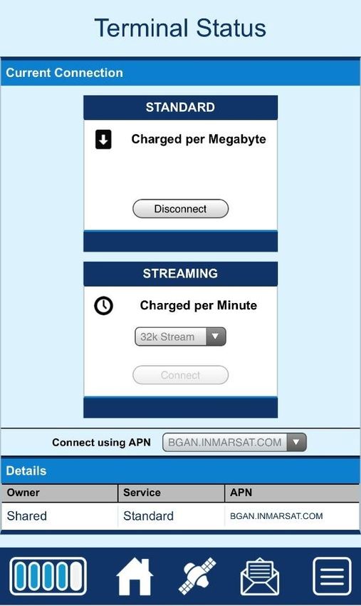
Safety symbols

                         The generic safety alert symbol            calls attention to a
                         potential personal injury hazard. It appears next to the
                         DANGER, WARNING, and CAUTION signal words as part of
                         the signal word label. Other symbols may appear next to
                         DANGER, WARNING, or CAUTION to indicate a specific type
                         of hazard (for example, fire or electric shock). If other hazard
                         symbols are used in this document, they are identified in this
                         section.
                         Additional symbols
                                         Warning Potential Radio Frequency (RF)
                                         hazard. Where you see this alert symbol and
                                         WARNING heading, strictly follow the
                                         warning instructions to avoid injury to eyes or
                                         other personal injury.
                                         Warning Where you see this alert symbol and
                                         WARNING heading, strictly follow the
                                         warning instructions to avoid personal injury.

                                         Danger Electric shock hazard: Where you see
                                         this alert symbol and DANGER heading,
                                         strictly follow the warning instructions to avoid
                                         electric shock injury or death.
                                   Warnings for Satellite Terminal

                                         Do not stand in front of the Antenna This
                                         device emits radio frequency energy. To avoid
                                         injury, do not place head or other body parts in
                                         front of the satellite antenna when system is
                                         operational. Maintain a distance of one meter or
                                         more from the front of the Satellite Terminal
                                         antenna.
                                         General Handle your Satellite Terminal with
                                         care. The outdoor unit is weather resistant per
                                         IEC 60529 IP56; however, do not submerge
                                         either unit. Avoid exposing your Satellite
                                         Terminal to extreme hot or cold temperatures
                                         outside the range -25ºC to +55ºC.
                                         Avoid placing the Terminal close to cigarettes,
                                         open flames or any source of heat.

vi   • Safety
     H64159 Revision A
Changes or modifications to the Terminal not
expressly approved by Hughes Network
Systems could void your authority to operate
this equipment.
Only use a soft damp cloth to clean the
Terminal.
To avoid impaired Terminal performance,
please ensure the unit’s antenna is not damaged
or covered with foreign material like paint or
labeling.
When inserting the SIM, do not bend it or
damage the contacts in any way. When
connecting the interface cables, do not use
excessive force.
In the vicinity of blasting work and in
explosive environments Never use the Satellite
Terminal where blasting work is in progress.
Observe all restrictions and follow any
regulations or rules. Areas with a potentially
explosive environment are often, but not
always, clearly marked. Do not use the
Terminal while at a petrol filling station. Do not
use near fuel or chemicals.
Qualified Service Do not attempt to
disassemble your Satellite Terminal. The unit
does not contain consumer-serviceable
components. Only qualified service personnel
may install or repair equipment.
Accessories Use Hughes approved accessories
only. Use of non-approved accessories may
result in loss of performance, damage to the
Satellite Terminal, fire, electric shock or injury.

Connecting Devices Never connect
incompatible devices to the Satellite Terminal.
When connecting the Satellite Terminal to any
other device, read the device’s User Manual for
detailed safety instructions.

                                  • Safety            vii
                         H64159 Revision A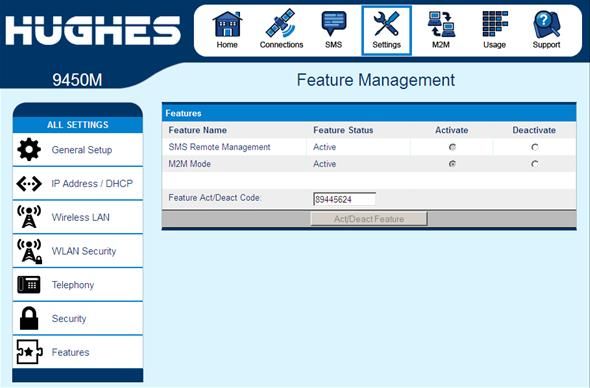
Pacemakers The various brands and models of
                           cardiac pacemakers available exhibit a wide range
                           of immunity levels to radio signals. Therefore,
                           people who wear a cardiac pacemaker and who
                           want to use a Satellite Terminal should seek the
                           advice of their cardiologist. If, as a pacemaker
                           user, you are still concerned about interaction with
                           the Satellite Terminal, we suggest you follow
                           these guidelines:
                               •   Maintain a distance of 20cm from the Wi-
                                   Fi antenna and your pacemaker:
                               •   Maintain a distance of one meter from the
                                   main antenna front and sides and your
                                   pacemaker;
                               •   Refer to your pacemaker product literature
                                   for information on your particular device.
                           If you have any reason to suspect that interference
                           is taking place, turn off your Satellite Terminal
                           immediately.
                           Hearing Aids Most new models of hearing aids
                           are immune to radio frequency interference from
                           Satellite Terminals that are more than 2 meters
                           away. Many types of older hearing aids may be
                           susceptible to interference, making it very difficult
                           to use them near a Terminal. Should interference
                           be experienced, maintain additional separation
                           between you and the Satellite Terminal.

                           Electrical Storms Operation of the Satellite
                           Terminal during electrical storms may result in
                           severe personal injury or death. Ensure the Below
                           Deck Equipment is properly grounded to the
                           vehicle chassis.

viii   • Safety
       H64159 Revision A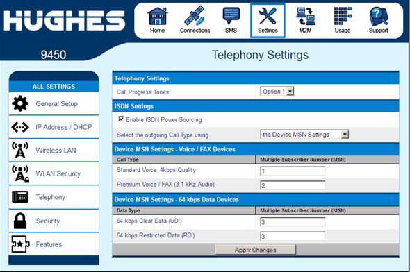
Introduction
Overview
           The Hughes Network Systems 9450 Broadband Satellite
           Terminal is your gateway to global communication. The
           9450 series terminal allows you to simultaneously send and
           receive IP packet and circuit-switched data via Ethernet
           (Power over Ethernet) ports and the Integrated Services
           Digital Network (ISDN) interfaces over the Inmarsat BGAN
           satellite network.
           Depending on the version, this unit offers you the following
           features and benefits:
             • Fully autonomous tracking antenna acquires and tracks
               the BGAN satellite signal while on the move
             • Optional antenna installation (magnetic mount) on
               vehicle roof
             • Includes RF cable and power cable for vehicular
               installation
             • Up to 492 Kbps data (transmit and receive) and 256
               Kbps streaming IP data rate (above 45 degrees look
               angle) for C10 and 128Kbps streaming for C11
             • Four RJ-45 Power over Ethernet (PoE) ports (except
               9450L and 9450LW)
             • Compressed voice calls (except 9450L and 9450LW)
             • 3.1KHz audio (above 20 degrees look angle to the
               satellite for C10 and above 45 degrees for C11) (except
               9450L and 9450LW)
             • ISDN UDI/RDI data (64Kbps) (above 20 degrees look
               angle to the satellite for C10 and above 45 degrees for
               C11) (except 9450L, 9450LW and 9450TW)
             • Multi-user capability for sharing a single unit
             • Selectable Quality-of-Service (QoS)
             • Full IP compatibility for Email, file transfer (FTP),
               browsing, VPN, etc.
             • Cost-effective “always-on” access – charges only for
               data sent and received
             • UMTS IP-based services
             • FCC and CE certified
             • Subscriber Identification Module (SIM) card security

                                                     • Introduction       1
                                                H64159 Revision A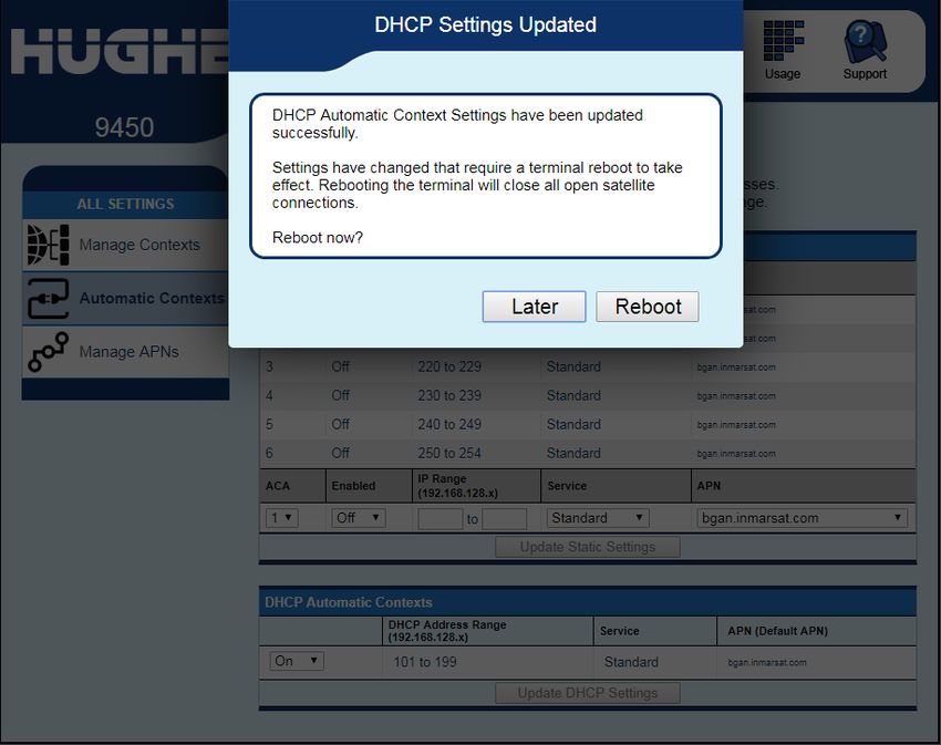
With the optional mag mount installation method, the unit is
                                             easy to install and connects in minutes. It is built for use in
                                             vehicular environments.
                                             In this document, the following names and abbreviations are
                                             used to identify the Satellite Terminal and your computer.
                                               Term      Definition
                                               IDU       Indoor Unit
                                               ODU       Outdoor Unit/antenna
                                             Terminal Satellite Terminal
                                                TE       Terminal Equipment (your computer)
                                                UT       User Terminal/satellite terminal

9450 Variants
                                             There are multiple versions of the 9450 each with different
                                             interfaces as listed in the table below. Depending on the
                                             version, certain features will not apply.
                                             The different models use different software release versions
                                             as shown below. The upgrader protects against loading the
                                             wrong release.
    9450 Model            Part Numbers                       Interfaces                        Software Release
    9450            Kit: 3500497-0001 C11     4 port 100BaseT Ethernet switch with PoE        5.7.x.y
                          3500497-0002 C10    802.11b WLAN
                          3500497-0010 C10    ISDN
                          3500497-0013 C11    2 RJ11 ports
                •   Radio: 3500462-0001
                •         or 3500462-0005
    9450E           Kit: 3500497-0008 C11     4 port 100BaseT Ethernet switch with PoE        5.7.x.y
                         3500497-0012 C10     ISDN
                •   Radio: 3500462-0003       2 RJ11 ports
    9450L           Kit: 3500497-0015 C11     4 port 100BaseT Ethernet switch only            5.7.x.y or 6.7.x.y
                         3500497-0014 C10
                •   Radio: 3500462-0006
    9450LW          Kit: 3500497-0019 C11     4 port 100BaseT Ethernet switch                 6.7.x.y
                         3500497-0018 C10     802.11b/g/n WLAN
                •   Radio: 3500462-0008
    9450TW          Kit: 3500497-0021 C11     4 port 100BaseT Ethernet switch with PoE        6.7.x.y
                         3500497-0020 C10     802.11b/g/n WLAN
                •   Radio: 3500462-0011       2 RJ11 ports

2           • Introduction
            H64159 Revision A
About this User Guide
This user guide contains the most up-to-date information
available on this product, on the date it was generated. It is
focused on the specific information needed to operate the
Hughes 9450 Land Mobile User Terminal.
For information on using LaunchPad, please refer to the
Inmarsat website where a copy of the ‘Inmarsat LaunchPad
Guide’ can be downloaded:
http://www.inmarsat.com/Support/bgan-firmware/bgan-
launchpad/
LaunchPad is not supported when the 9450 is in M2M mode.
Package Contents
When you unpack the Land Mobile Terminal Kit package,
you will find the following:
• BGAN Land Mobile Tracking Antenna Kit
• Hughes 9450 BGAN Satellite Modem Kit
Your Service Provider will supply you with a Subscriber
Identification Module (SIM) and its PIN, and Satellite
Terminal configuration instructions – you will need these to
access the network. Note: The SIM card may also have
four (4) MSISDN numbers associated with it for various
ISDN services:
• 4K Voice
• 3.1KHz Audio/Fax
• 64K UDI data
• 56K RDI data
Minimum System
Requirements for
Laptop/PC
These are the minimum computer system requirements for
successful interface with the Satellite Terminal:
• Internet Browser: Chrome (9450 SW release 6.7.1.1 and
above), Internet Explorer, Edge, Firefox or Safari.
• Introduction 3
H64159 Revision A• PC Support for at least one of these interfaces: Ethernet,
or WLAN (802.11b or b/g).
• 100 MB of free hard disk space (if using LaunchPad).
Getting Started
This guide is the simplest and quickest way to connect to
the BGAN network. If you are a first time user, you will
be guided through the procedure for powering up your
terminal, obtaining a GPS fix, connecting your computer
to the terminal and registering with the BGAN network.
You are then ready to start using voice and broadband
services.
Installing your
terminal
Install the Hughes 9450 terminal according to the
Installation Guide supplied with the terminal for either the
C10 or C11 antenna. You can also download the Installation
guides and User manuals from our website at
www.bgan.hughes.com . Please refer to the Installation
Guides for grounding instructions.
Terminal LED
functionality
The 9450 IDU has 4 LEDs with the following functions:
Power: Green when IDU is powered on. Off when IDU is
powered off. This LED is integrated in the On/Off switch.
Network Registration: Green when registered and attached
with Inmarsat BGAN network; Off otherwise.
GPS: Flashing Green while acquiring fix and solid Green
when valid GPS fix acquired. The GPS LED turns off when
the UT registers with the network and the network LED
turns on.
H/W Fault: Red if HW fault detected, e.g.: IB fault, no
communication to antenna or no GPS. Off otherwise.
4 • Introduction
H64159 Revision AThe 9450 IDU has a four RJ-45 connector with 2 LEDs for
each port with the following functions:
Green/Red bicolor: Green indicates Link active; Red
indicates a power over Ethernet PD device is connected and
is being powered by the IDU. When both functions are
active, it will appear Orange in color.
Green: Traffic indicator
• Introduction 5
H64159 Revision AUsing the Hughes 9450
Auto start
configuration
Since the Hughes 9450 terminal is equipped with a
tracking antenna, the default configuration for the Hughes
9450 Land Mobile Terminal is as follows:
• The Hughes 9450 is configured to automatically register
with the network by default: The terminal will
automatically attempt to register with the network once
the tracking antenna has acquired the satellite signal and
obtained a GPS fix.
• The IDU has a power switch and an ignition sense line.
For the unit to turn on, the power switch must be in the
ON position and 12V or 24V applied to the ignition
sense line. Refer to the 9450 Installation Guide P/N
3004129-0001.
6 • Using the Web UI
H64159 Revision APower up and the
connection to the
Internet
After power is applied, the Hughes 9450 IDU and Hughes
Tracking Antenna will begin their start-up sequence. The
tracking antenna will begin its search for the BGAN
satellite and the antenna motors may be heard during this
time. Note that the tracking antenna must have line of sight
to the BGAN satellite. Once the antenna has locked onto
the BGAN satellite, it will continue to make minor
adjustments to acquire optimum signal strength. The
antenna may be heard ‘twitching’ during this time.
Eventually the antenna will sit at an optimum position
while the vehicle is stationary.
Once the vehicle starts moving, the Hughes Tracking
Antenna will automatically track the satellite signal and
keep the antenna pointed towards the satellite. During
short outages (e.g. while driving under a bridge, etc.) the
antenna will remain in the same position and will pick up
the satellite signal immediately. For longer outages the
antenna may need to repeat the search pattern to reacquire
the satellite signal.
Circuit switched and packet switched connections will
typically recover from signal outages of less than 60
seconds. User intervention will be required to reactivate
circuit switched connections for outages longer than 60
seconds and may be required for packet switched
connections depending upon the actual length of outage.
Packet switched connections like FTP are more robust
than circuit switched connections in the network.
Connecting the
terminal to the
computer
You can connect your computer to the 9450 IDU with one
or more of the following interfaces
• Ethernet
• WLAN (not 9450E or 9450L)
• Using the Web UI 7
H64159 Revision A• During initial setup, the terminal can only be configured
using an Ethernet connection. Once the terminal has
been configured, all interfaces can be used for data
transfer.
Connecting by Ethernet
To connect the BGAN terminal to a device using Ethernet,
connect an Ethernet cable to your device’s Ethernet port,
and insert the other end of the connector into one of the
four Ethernet ports on the 9450 IDU. These four Ethernet
ports support Power-over-Ethernet (PoE) (except on the
9450L and LW).
Power over Ethernet (POE)
Note, PoE is not supported on the 9450L or LW.
All four PoE ports are powered by a single 48 Volt DC
power supply. The total power supplied by PoE is limited
to 30.8 W maximum for 12 V installations and 61.6 W
maximum for 24 V installations. The ports can provide
power to class 1, 2, and 3 devices as long as the total
power does not exceed the wattage based on the input
voltage provided. If a device is connected to a port that
exceeds the maximum power available, power will not be
provided to that port. The existing connections will not be
affected.
Connecting by WLAN
Note: WLAN is not available on the 9450E or 9450L.
If you have not previously used the IDU’s WLAN
interface, it has to be enabled from the internal web UI
with your computer connected to the IDU using the
Ethernet interface.
• WLAN Power: The default is off, which disables the
WLAN feature.
• SSID (network name): The default is BGAN, but you
can change it to whatever you want.
• Channel Number: This controls the radio channel
number (1 through 11) used by the access point. To meet
FCC regulations, channels 12 to 14 are not supported.
8 • Using the Web UI
H64159 Revision AWhen configuring the WLAN, you can enable the
Wireless security protocol and MAC address filtering for
added security.
Once the WLAN is “Enabled” and configured, any device
with a WLAN interface can detect the IDU’s WLAN SSID
and connect to it automatically.
The 9450LW and TW support up to 4 WLAN clients.
WLAN Security
For WLAN security, select from the following:
9450: No protection, 64 bit WEP, or 128 bit WEP
9450LW/TW: No protection, WPA, or WPA2
MAC Filtering: For added security, check the box to
“Enable” MAC Filtering. You can define up to 10 MAC
addresses that are allowed to connect to your WLAN.
When WLAN is enabled, unauthorized users may be able
to access your BGAN service. If WEP or WPA is enabled,
you must provide other WLAN users with the security key
in order for them to connect to the terminal. In NAT mode
you can go to the Manage Connections page to see what
computers are actually using the BGAN service.
Connecting by ISDN
Note: ISDN is not available on the 9450L, LW or TW.
Connect an ISDN cable to your computer’s or phone’s
ISDN port, and insert the other end of the connector into
the Terminal’s ISDN port.
To dial, prefix the international number with 00 and
terminate with #. For example, to dial a number in the
USA, enter: 0018005551234#
To receive incoming calls, you must configure your ISDN
device with the MSN (Multiple Subscriber Number) of the
service it supports. See the ISDN section for information
on configuration of MSNs. To configure the MSN in your
ISDN device, refer to the user guide of your ISDN device.
• Using the Web UI 9
H64159 Revision AInmarsat only allow Class 11 terminals to use ISDN at
elevation angles of 45 degrees or greater and Class 10
terminals at elevation angles of 15 degrees and greater.
Check with your service provider for full details.
Connecting by RJ11
Note: RJ11 is not available on the 9450L or LW.
You can connect an analog phone or fax machine to the
RJ11 ports:
• The FAX port is configured for 3.1k service for fax
• The TEL port is configured for speech service for voice
calls
Inmarsat only allow Class 11 terminals to use Fax or
3.1kHz at elevation angles of 45 degrees or greater and
Class 10 terminals at elevation angles of 15 degrees and
greater. Check with your service provider for full details.
To dial, prefix the international number with 00 and
terminate with #. For example, to dial a number in the
USA, enter: 0018005551234# (00 + Country code + phone
number)
Operational note: RJ11 and ISDN handsets cannot be
connected at the same time. The 9450 will configure itself to
ISDN or RJ11 mode depending on which type of handset is
plugged in first and will be in this mode thereafter.
To switch modes, the 9450 must be rebooted with only the
desired handset connected. If both types of handsets are
connected at power-on, the 9450 will default to ISDN
mode and RJ11 will not be operational.
10 • Using the Web UI
H64159 Revision ACoverage Map
The Inmarsat BGAN service is operated with 4 satellites as
shown below. The Hughes 9450 terminals will perform
best in areas where the elevation angle is 20 degrees or
higher. Lower elevation angles increase the probability of
signal outages caused by trees, buildings and hilly terrain
and may severely impact the usability on the move.
• Using the Web UI 11
H64159 Revision AOperation in the MEAS cutout area
I-4 MEAS has a cutout area in its coverage over China and
nearby parts of Asia. In this area, I-4 Asia Pacific (APAC)
must be used even if MEAS is closer. For best operation in
this area configure the UT to use only APAC from the
General Setup page (31).
12 • Using the Web UI
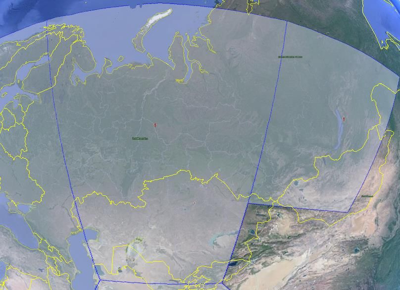
H64159 Revision AOperation in the Russian Federation
In the Territory and National Waters of the Russian Federation
covered by the three Regional beams of I-4 MEAS shown
below, end-users must use MEAS rather than Alphasat
(EMEA) or I-4 Asia Pacific (APAC), even if one of these
satellites is closer. When operating in this region, you can
configure the UT to only use MEAS from the General Setup
Page. In areas within the Russian Federation, but not covered
by the I-4 MEAS satellite, use I-4 Asia Pacific (APAC).
Starting in release 5.7.4.0, the UT supports the Preferred
Satellite Info feature. If the UT in this region tries to register
on the wrong satellite, the network will command it to switch
to the correct satellite.
• Using the Web UI 13
H64159 Revision AUsing the Web UI
Accessing the Web UI
The Hughes UT includes its own internal Web User
Interface (UI). To access the web UI, open your favorite
Web Browser and type in the internal IP address of the UT
e.g. http://192.168.128.100. The web UI opens up to the
“Home” page as shown below:
14 • Using the Web UI
H64159 Revision AIf the 9450 has been converted to an M2M terminal, the
Home page icon will look like this e.g. 9450M. Note
streaming QoS is disabled in M2M mode.
• Using the Web UI 15
H64159 Revision AHome page
The Home page shows the current terminal status and
allows you to setup your initial data connection.
On the left side of the page is the Status bar. These items
are updated automatically when the status of any of these
items change.
1. Connection: This field indicates whether you are
Registered with the Network. It also shows the PS and
CS status, beam type with current satellite and receive
signal quality.
a. PS Attach Status: This field indicates whether
you are PS (Packet Switch) attached with the
Network. You will still need to setup a PDP
context in order to send PS data.
b. CS Attach Status: This indicates whether you are
CS (Circuit Switch) attached with the Network.
Once you are CS Attached and Registered with the
network, you can make CS calls.
2. GPS: This field displays the current GPS position
status. If you have received a GPS fix and the
Network GPS policy has been received and it allows
the GPS position to be shown to the user, it will
display the Latitude, Longitude, Fix Quality, and the
Last time the GPS position was updated. Time
displayed is UTC time. If it displays “Waiting”, the
terminal has a GPS fix but it is waiting for the GPS
policy from registration before displaying the
coordinates.
3. BGAN Terminal: This field indicates the WLAN
status (except on the 9450E or 9450L).
4. Antenna Unit: This field indicates the detailed state of
the tracking antenna.
• The different tracking states are as follows:
• Initial – this is when the 9450 is first powered
On
• Unknown – this state is when the 9450 is
powering up and communication to the
antenna has not started yet.
• Tracking & Tuning – this state is when the
antenna starts to track the satellite in both
azimuth and elevation and is optimizing its
orientation.
• Tracking – this is the normal state when the
antenna is tracking the satellite.
16 • Using the Web UI
H64159 Revision A• Elevation: the current elevation look angle of the
antenna.
• The frequency of the global beam in MHz that the
antenna is attempting to track is displayed. If the unit
is experiencing problems, use the table below to verify
the antenna is searching for the correct satellite for
your location.
The frequency is the frequency of the global beam.
Possible values are the primary and secondary frequencies
of the four satellites.
In the middle of the Home page you will find the following
items:
Current Connection field allows you to activate data
connections for your TE. You can activate a Standard connection
or a Streaming connection. For streaming connections use the
drop-down box to select the data rate for the stream. Streaming
QoS is not available when configured for M2M mode.
Connect using APN field allows you to control the APN used
for the connection.
Details show the status of the connection for this TE.
Visible Satellites shows the satellites visible for your current
location and the pointing information.
Reference the screenshot below. The antenna angle under the
Visible Satellites section (46.5°) may not always be exactly the
same as seen under the Antenna Unit section showing Elevation
(46°). This is due to the wide beam width of the antenna.
• Using the Web UI 17
H64159 Revision AThe following figure shows how the UI looks if you activate a
Standard connection. Use the Disconnect button to deactivate
your connection.
18 • Using the Web UI
H64159 Revision AConnections
The Connections icon has three configuration areas to select
from: Manage Contexts, Automatic Context Activation (ACA),
and Manage APN. The following section will review each of
these pages.
Manage Connections
Manage Connections page under the Data tab allows the user to
setup and configure PDP contexts (data connection) for any TE
that is connected to the UT. It also shows you all current Active
Connections.
Open a New Connection - To open a new connection, enter the
required data in the lower box.
Owner – Your current IP address is shown by default (.101), but
you can change it to control connections for any other device
connected to the terminal. The page automatically displays
• Using the Web UI 19
H64159 Revision Aentries for all detected devices and these entries can be selected
to activate connections for those devices.
Service - Select the service that you want by clicking on the
down arrow. The drop-down list shows all of the different QoS
types: standard, streaming 32K, streaming 64K, streaming 128K.
and streaming 256K. Select the appropriate service required.
APN - The APN is read from the SIM card, but if you have other
APN’s defined (go to Manage APN page), you can use the down
arrow to select a different APN. Once everything is defined
correctly, click on the “Open Selected Connection” button. The
new context will appear in the All Active Connections field
above.
Close an Active Connection - In the upper field, all active
connections are shown, and you can select and close any of these
connections unless an Administration Password has been
enabled. See Security Section for more information about the
administration password.
Username (UN)/Password (PW): Some Service Providers
require a username and password to be used when setting up a
connection. This is often required when using Static Global IP
addresses assigned by the Service provider. These fields can be
entered when defining a new APN or when you select a different
APN.
Automatic Contexts
Note: the ACA page is not available in NAPT mode.
This web page allows you to use Automatic Context Activation
(ACA) in two different ways;
• One way is to use a static IP addresses in the TE device so
you can establish an automatic PDP context with any QoS
that is offered by the network (upper half of the web page).
• The second way is to use DHCP IP addresses from the UT
so you can establish an automatic standard PDP context for
any TE that connects via DHCP to the UT (lower part of the
web page).
• There are also two ways to set the ACA whether you choose
Static or DHCP. You can choose whether the context should
20 • Using the Web UI
H64159 Revision Abe activated immediately for that IP address (“ON”), or if
the context should only be activated when the TE attempts to
send data to the satellite link (“Data”):
o “Always ON”: Select ON in the drop-down menu
if you want the context to be ON all the time for
that specific IP address.
o “Data”: Select Data if you want the context to be
activated when the TE attempts to send data to the
satellite link
When using “Data” ACA, if the context is ever deactivated, it
will be reactivated when more data is sent.
As of release 5.7.1.2 and higher, the “ON” option will always
reactivate the context if it is deactivated, even if data is not sent
by the TE.
Static IP Automatic Contexts: You can configure your own
range of static IP addresses and QoS’s to use with a static
automatic context.
To turn on a particular range of static addresses, select “On” or
“Data” from the drop-down list and choose a range of addresses,
low and high to use (e.g. 192.168.128.200 to 192.168.128.202)
or you can leave the defaults (192.168.128.200 to
192.168.128.209).
In release 5.7.2.4 and higher, if the ACA hi and low IP addresses
are the same and the ACA is set to "ON", then the UT will
activate the PDP context at startup without waiting for any IP
packet from the local device. This allows contexts to be set up
for devices that do not ARP. Also, you can use an IP address in
the DHCP range so you can control the APN plus username
/password that is used for a particular local IP address. This is
useful when using global static IP addresses that are to be
assigned to particular local devices.
Next select the desired QoS for that range of IP addresses (e.g.
Standard). The APN listed is the default APN read from the
SIM card (bgan.inmarsat.com). If your SIM is provisioned for
more than one APN, then you can select a secondary APN from
the drop-down list.
• Using the Web UI 21
H64159 Revision AIf you want to setup additional ranges of addresses, please follow
the same instructions as above.
You cannot overlap the IP address ranges. If you do, an error
message will pop-up telling you that you have an overlap region.
Check all of the ranges for overlaps and try again.
When you are finished, click on “Apply” and you should see a
message saying, “Operation Successful”.
DHCP Automatic Contexts: This option allows you to set up
the UT for dynamic standard ACA. This means that any device
connected to the UT via DHCP, whether wired or wirelessly will
automatically receive a standard context.
To activate this feature, select “On” or “Data” from the drop-
down list under DHCP Automatic Context section and click on
“Apply”. The APN will be the default APN configured on the
Manage APNs page.
22 • Using the Web UI
H64159 Revision AOnce you hit “Apply” you will get a pop-up message saying that
the ACA settings were updated successfully and to take effect
you will have to reboot the terminal.
Once you reboot the terminal, check that the settings took effect.
• Using the Web UI 23
H64159 Revision ATo see if the context has been setup properly, click on the Data
tab>Manage Connections Page and this will show you all
contexts that have been setup (active or inactive). See screen
shot below.
24 • Using the Web UI
H64159 Revision AManage APNs
Some SIM cards are provisioned with multiple APNs, so you can
use this page to pre-configure those additional APNs if needed.
Once the APN is defined, you can select it from the drop-down
list without having to put in the username and password every
time.
Add an APN field – Use this field to add an additional APN that
you want to use, or to edit an existing APN. For adding a new
APN, type in the new APN and username (if required) then
select Add New APN. If the APN requires a password, select
the “APN Requires Password” box. If you want to save the
password so you don’t have to re-type it each time you configure
a PDP context for that APN, check the “Remember my
Password” box and then click the Add New APN button. (The
username is always saved if entered.) The new APN name will
show up in the Defined APNs field with the Username in
parentheses. This APN will now be available to use from any
APN drop down menu.
User Name /Password: Some Service Providers require a
username and/or password to be used when setting up a
connection. This is often required when using Static Global IP
addresses assigned by the Service provider.
• Using the Web UI 25
H64159 Revision AThe screenshot above shows the new APN that was added, in the
Defined APNs section.
If you wish to edit an existing APN, first select the APN to edit
under the Defined APNs section on the left. The information for
that APN will then appear in the Add an APN field to the right,
and you can then edit it. Click the Save Changes button to save
your changes.
Make Default. If you wish to change the default APN, select an
entry in the list of Defined APNs and then click Make Default.
This APN will now be the default APN on the other context
control pages.
26 • Using the Web UI
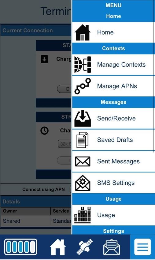
H64159 Revision ASMS
You can manage SMS text messages from the SMS pages which
provide a similar function to LaunchPad. You must have a valid
Service Center number configured in order to send messages –
see the SMS Settings Page.
Send/Receive
The Send/Receive page allows you to view your Inbox box
messages and Compose a new message. If there are more than
10 messages, you can view the older ones by changing the page
number. You can also reply to received messages or forward
them to another number.
You may need to periodically delete messages to prevent the
SIM from filling up which will prevent the receipt of new
messages. You can select a single message by checking the box
next to the message and press the “Delete Checked” button. To
delete multiple messages just select the check box next to each
message you want to delete and click the “Delete Checked”
button.
After composing a message, you can save it to drafts rather than
sending it, by pressing the “Save” button.
• Using the Web UI 27
H64159 Revision ASaved Drafts
The Saved Drafts page allows you to view previously saved
messages. After editing a message, you can resave (Save) or
send the message (Send). You can also compose a message
from this page.
Sent Messages
The Sent Messages page allows you to view previously sent
messages. Again, you may need to periodically delete messages
to prevent the SIM from filling up. You can also compose a new
message from this page.
28 • Using the Web UI
H64159 Revision ASMS Settings
On the SMS Settings page you can configure the default settings
for messages. You must have a valid Service Center number
configured in order to send messages. The default Service
Center number is +870772001799.
• Using the Web UI 29
H64159 Revision AOn the Remote SMS Feature section, you can enable the unit to
receive and act on special remote control SMS messages. This
Feature is active by default on the Features page, but before it
can be used, it must be Enabled on this page.
You can configure the password for remote control SMS
messages. Note: If you activate this feature and do not change
the password, it is possible that other people may be able to send
control messages to your unit. In 6.7.1.1 and above, there is no
default password and a password must be entered when
activating the feature.
Remote control messages will be deleted after they are received
and will not be stored in the SIM.
Senders White-list – is a list of numbers that the terminal will
allow a remote SMS message to come from. When entering the
number use the + symbol in front of the country code e.g., +870
or just start with the country code e.g., 870. Do not use 00 in
front of the country code.
30 • Using the Web UI
H64159 Revision ASettings page
General Setup
This page allows the user to configure various parameters of the
UT. A description of each item on this page follows:
Terminal Startup – The default configuration for the 9450
terminal has Bypass Antenna pointing and Always power on
checked and grayed out due to the tracking antenna.
Connection: Always Connect to Satellite: The default
configuration is always set to Automatic. This parameter is used
within a satellite overlap region and allows the user to override
the default satellite (selected by the 9450 terminal based upon
elevation angle/GPS location) and select a different satellite.
This change does not take effect until the UT is reset. When set
to Automatic, the UT will select the satellite based on the unit’s
GPS position. When set to a specific satellite, it will attempt to
use that satellite only. Be careful to select the correct satellite for
your position.
Secondary Frequency Search: (New in release 5.7.4.0.) By
default the antenna will not search for secondary satellite
frequencies. Inmarsat does not broadcast the secondary
• Using the Web UI 31
H64159 Revision Afrequencies and so searching for them would slow down antenna
satellite search and recovery, especially in blockage or overlap
conditions. However, if Inmarsat should ever announce they
have switched to using a secondary frequency on a satellite,
enable this parameter if using that satellite.
Streaming – By enabling this parameter, the user can turn on a
timer for inactivity for a streaming QoS that has been set up.
The timer is in either seconds or minutes and will tear down a
streaming context after X seconds or minutes of inactivity.
Emergency Call Numbers: Allows the user to add the
emergency call number that is applicable in the part of the world
where the terminal is being used, if it is not already defined.
Some 9450 versions offer a reduced set of interfaces and so the
WLAN and Telephony pages are only available when applicable.
For example, the General Settings page appears as shown below
on the 9450L with reduced links in the status bar.
32 • Using the Web UI
H64159 Revision AIP Address/DHCP Settings
Terminal Local IP Address: This page allows the user to
change the local IP address of the terminal from the default
192.168.128.100 IP address. All four octets are available to
change. Once the local IP address is changed on this page and
applied, the IP address ranges for the DHCP server, the Manage
Context page and ACA page will also be changed automatically.
Updates to this field will not take effect until the UT is
rebooted.
DHCP Server: allows the DHCP server in the UT to be turned
on or off by checking the Enable box.
DHCP Address Range: This allows the user to set the range of
DHCP addresses that are given out by the UT to any connected
TE.
Lease Time when idle: Idle-mode DHCP Lease Time refers to
the DHCP lease time when the UT is not connected to the
network. This parameter allows the user to change the default
time (60 seconds) that the DHCP lease to the TE is good for.
This parameter was introduced because of a problem with some
models of Cisco routers that will not accept a short DHCP lease
time.
The longer the Idle-mode DHCP lease time, the longer it will
take the Network/UT to update the TE with the correct DNS
servers for web browsing after establishing a data context.
Lease Time when connected: The Connected-mode DHCP
Lease Time refers to the DHCP lease time when the UT is
connected to the network. Most users will have no need to
change this parameter.
• Using the Web UI 33
H64159 Revision ANetwork Operating Mode: The Netmode field indicates the
mode of operation of the terminal. In NAT mode the UT will
translate between the local and global IP addresses. In NAPT
mode the UT will also do port translation so multiple local
devices can share a single context. In Relay mode the UT will
supply the global IP address to the TE once a PDP Context is
established. Relay mode is single user/single PDP Context and
only supports a single connected TE. In the 9450LW and TW,
Relay mode cannot be used with WLAN.
Note: Updates to this field will not take effect until the UT is
restarted.
34 • Using the Web UI
H64159 Revision ANat Mode
In NAT mode once a PDP context is active, the UT will
translate between the local and global IP addresses. This is a
basic NAT that only performs IP address translation. It does not
use port translation.
NAPT Mode
In NAPT mode multiple devices share a single PDP context.
The port translating NAT modifies both IP addresses and port
numbers so multiple devices can share the single global IP
address assigned to the PDP context.
In NAPT mode, only a single context is supported. By default,
the Always On Context is activated on the M2M page. The ACA
page is removed. A Port Forwarding page is added under
Settings and can be used to configure the DMZ and Port
Forwarding.
NAPT is the default mode of operation in 6.7.1.0 and above.
This was chosen as it simplifies operation of the terminal,
especially for WLAN clients.
Relay Mode
In Relay mode the UT will supply the global IP address to the
TE when the context is established. Relay mode is single user
and only supports a single connected TE.
In Relay mode DHCP is required to provide the global IP
address to the TE. When the context is activated, the DHCP
server in the UT will NACK the next DHCP lease renewal from
the TE and assign the global IP address assigned by the network.
The local IP connection will be torn down and reestablished as
the IP address changes. Similarly, when the context is
deactivated the DHCP server will NACK the lease renewal and
then reassigns the original private IP address.
LaunchPad and the Web UI will lose and reestablish their
connections to the terminal as the IP address is changed.
To make the IP address change happen quickly a short DHCP
lease should be used. The terminal defaults the DHCP lease time
to 60 seconds in idle and connected mode.
Relay mode only supports a single user TE.
WLAN is not supported in Relay mode with the 9450LW or
TW.
• Using the Web UI 35
H64159 Revision AEthernet MAC Address Filtering: When this feature is
enabled, only the MAC addresses that you select can connect to
the terminal. A maximum of ten (10) addresses can be allowed.
Check the box to “Enable MAC Address Filtering”
If any TE is already connected to the terminal via Ethernet, the
MAC address of that TE will be detected and show up in the
“Add a Detected Device” field.
To add the detected MAC address, click on the address to
highlight it and then click Add. It will now show up in the
“Allowed MAC Address” field.
Port Forwarding Page
The Port Forwarding page is only available in NAPT mode and
includes:
• DMZ – if enabled, all packets received from the space
link that are not routed to other addresses will be
forwarded to the DMZ host address.
• Port Forwarding Rules. These fields allow you to
configure rules defining how packets of particular
protocols are routed, e.g. TCP port 80 for HTTP. Port
Forwarding rules are applied before the DMZ rule.
In the 6.7.x.y releases, the third octet of the IP address is
configurable to support the separate WLAN subnet.
36 • Using the Web UI
H64159 Revision AWireless LAN
The Wireless LAN settings page allows the user to enable,
disable, and configure the Wireless LAN functionality of the
terminal. This page is not available in the 9450E or 9450L.
The Wireless LAN Security is controlled on a separate web page
– WLAN Security.
If you have not previously used the terminal’s WLAN interface,
it must first be enabled from this page using a computer
connected to the terminal using an Ethernet connection. Once
WLAN is enabled/configured, TEs can connect to the terminal
wirelessly.
The page from release 5.7.x.y for the 9450 is shown below.
• Using the Web UI 37
H64159 Revision AFields on this page include:
Enable Wireless LAN Interface: Turns the Wireless LAN
interface on/off. The default is off (unchecked).
Network Name (SSID): The default is “BGAN”, but you can
change it to whatever you want.
You can “hide”/prevent the SSID from being broadcast. This
feature can make WLAN hard to use and does not provide real
security and so was removed in the newer 9450LW and TW.
Network Region: There is only one region for all countries.
Network Channel: This controls the radio channel number (1
through 11) used by the access point. To meet FCC regulations,
channels 12 to 14 are not supported.
If performance issues occur over the WLAN interface, changing
the Channel may help.
In release 6.7.x.y for the 9450LW and TW, a new field is added
to allow the user to configure the IP address for the WLAN
interface. In the LW/TW the WLAN card must be in a different
subnet from the Ethernet ports. By default it is set to a subnet 1
38 • Using the Web UI
H64159 Revision Ahigher than the Ethernet subnet, e.g. 192.168.129.100. The
WLAN clients will be assigned addresses in this subnet.
The 9450LW and TW do not allow hiding of the SSID.
• Using the Web UI 39
H64159 Revision AWireless LAN Security
This page allows the user to configure security for the wireless
link. Note: the page is not available in the 9450E or 9450L.
For security, select from the down arrow:
9450 No protection, 64 bit WEP, or 128 bit WEP
9450LW/TW No protection, WPA, or WPA2
For WEP, you can define the WEP key or use the default key,
which is formulated using the IMEI number of the terminal (e.g.
IMEI number plus 0123456789).
• Hexadecimal 128-bit: Requires 26 characters.
Recommended
• Hexadecimal 64-bit: Requires 10 characters
For WPA and WPA2 on the 9450LW and TW, define an 8 to 63
character passphrase.
40 • Using the Web UI
H64159 Revision AYou can also read