Learning Direction Fields for Quad Mesh Generation
←
→
Page content transcription
If your browser does not render page correctly, please read the page content below
Eurographics Symposium on Geometry Processing 2021                                                                                Volume 40 (2021), Number 5
K. Crane and J. Digne
(Guest Editors)

                    Learning Direction Fields for Quad Mesh Generation

                                        Alexander Dielen                 Isaak Lim            Max Lyon             Leif Kobbelt

                                                              Visual Computing Institute, RWTH Aachen University

         Abstract

         State of the art quadrangulation methods are able to reliably and robustly convert triangle meshes into quad meshes. Most of
         these methods rely on a dense direction field that is used to align a parametrization from which a quad mesh can be extracted.
         In this context, the aforementioned direction field is of particular importance, as it plays a key role in determining the structure
         of the generated quad mesh. If there are no user-provided directions available, the direction field is usually interpolated from
         a subset of principal curvature directions. To this end, a number of heuristics that aim to identify significant surface regions
         have been proposed. Unfortunately, the resulting fields often fail to capture the structure found in meshes created by human
         experts. This is due to the fact that experienced designers can leverage their domain knowledge in order to optimize a mesh
         for a specific application. In the context of physics simulation, for example, a designer might prefer an alignment and local
         refinement that facilitates a more accurate numerical simulation. Similarly, a character artist may prefer an alignment that
         makes the resulting mesh easier to animate. Crucially, this higher level domain knowledge cannot be easily extracted from local
         curvature information alone. Motivated by this issue, we propose a data-driven approach to the computation of direction fields
         that allows us to mimic the structure found in existing meshes, which could originate from human experts or other sources. More
         specifically, we make use of a neural network that aggregates global and local shape information in order to compute a direction
         field that can be used to guide a parametrization-based quad meshing method. Our approach is a first step towards addressing
         this challenging problem with a fully automatic learning-based method. We show that compared to classical techniques our
         data-driven approach combined with a robust model-driven method, is able to produce results that more closely exhibit the
         ground truth structure of a synthetic dataset (i.e. a manually designed quad mesh template fitted to a variety of human body
         types in a set of different poses).
         CCS Concepts
         • Computing methodologies → Shape analysis; Neural networks; Mesh models;

1. Introduction                                                                          tional edge loops around surface regions that are likely to deform,
                                                                                         such as the eyes or mouth of a human character. Furthermore, ir-
Mesh quadrangulation, i.e. the process of converting a given trian-
                                                                                         regular vertices are often placed in approximately planar regions
gle mesh into a quadrilateral mesh, is a fundamental problem in
                                                                                         in order to hide visual artifacts. For numerical simulation on quad
computer graphics and geometry processing with applications in
                                                                                         meshes, designers align and specify different sizes of quads based
character animation and physics simulation. Unfortunately, quad-
                                                                                         on their expert knowledge on how simulation solvers behave. It is
rangulating a given triangle mesh by hand is both labor-intensive
                                                                                         unclear how exactly the local curvature information relates to the
and cumbersome, as it requires a user to manually place individual
                                                                                         expert knowledge in these various domains.
quads on the surface of the input mesh. Because of this, a number of
authors have proposed fully automatic quadrangulation techniques                            To address this issue, a number of authors have proposed meth-
[BZK09; BCE*13; CBK15; JTPS15].                                                          ods that incorporate user-guidance into the remeshing process. The
                                                                                         method presented in [TPSS13], for example, enables users to define
   These fully automatic techniques work well on input shapes for
                                                                                         patch layouts using a sketch-based interface. Similarly, the tech-
which a meaningful alignment of quads can be computed from lo-
                                                                                         niques described in [JTPS15; ESCK16] allow users to override the
cal curvature information. They do, however, encounter problems
                                                                                         edge flow of an automatically generated quad mesh using brush-
when faced with shapes that do not offer strong curvature guidance.
                                                                                         strokes. A common drawback of these methods is that querying a
The problem is exacerbated by the fact that, depending on the ap-
                                                                                         user repeatedly for guidance can be somewhat time-consuming.
plication, a designer might prefer an alignment that is not directly
related to principal curvature directions. In the context of character                     We present a data-driven approach that does not require any
modeling and animation, for example, artists usually place addi-                         user-guidance. Our method learns the structure present in exist-

© 2021 The Author(s)
Computer Graphics Forum © 2021 The Eurographics Association and John
Wiley & Sons Ltd. Published by John Wiley & Sons Ltd.
A. Dielen, I. Lim, M. Lyon, L. Kobbelt / Learning Direction Fields for Quad Mesh Generation
ing meshes, which allows for the generation of quad meshes that PPTS14; JFH*15; DVPS15]. All these methods have in common
exhibit many features typically reserved to manually created ones. that the desired alignment is derived from the surface geometry –
To this end, we combine a field-guided quadrangulation technique mainly its curvature. This works well on shapes where alignment to
with a neural network that infers direction fields from unstruc- principal curvature is sufficient. For cases where a user may desire
tured triangle meshes. We prefer these continuous outputs instead different alignment, user input can be considered during field gen-
of directly inferring a quad mesh from a neural network, since this eration. This works particularly well with the methods proposed in
would require the network to make a series of discrete decisions [ESCK16; JTPS15] that provide quick results enabling interactive
(each of which can have catastrophic effects on the final output). workflows. These methods allow the user to manually place singu-
A state-of-the-art quadrangulation method can then robustly com- lar vertices, and to specify general edge alignment or even explicit
pute a quad mesh from the triangle mesh and the network inferred edge loops connecting the singularities. Due to the robustness and
direction field. reliability of these methods as well as the high quality of the results
that can be achieved by them, we make use of such a field guided
Contribution We investigate which type of direction field best quad meshing method [CBK15] in this work.
captures the structure found in manually created quad meshes. Other interactive quad meshing methods require the user to par-
Based on our findings, we propose a neural network that infers tition the surface into patches which are then filled with suitable
frame fields from unstructured triangle meshes. Furthermore, we quad grids [NSY09; TPSS13; PBJW14; TPS14]. C AMPEN et al.
present a number of loss functions that can be used to train our propose in [CK14] a quad meshing algorithm which requires the
network. We demonstrate the applicability of our approach on the user to specify the dual loops of the desired mesh. These interac-
challenging task of remeshing human characters models and com- tive methods have in common that, while they do provide detailed
pare our results with those obtained using three existing curvature- and explicit control of the resulting mesh, they also require exten-
based methods. Our experiments show that our method performs sive user input which increases the overall time required to generate
favorably. Using an ablation study, we validate our design choices quad meshes.
for the neural network and the losses.
Data-driven Remeshing The data-driven quadrangulation
2. Related Work method by M ARCIAS et al. in [MTP*15] is related to this work in
the sense that they also aim to extract domain knowledge encoded
Geometric Deep Learning Neural Networks that work on dif- in existing quad meshes for the alignment and placements of
ferent 3D shape representations as input are well established. quads on input shapes. However, they only extract and compare
Input representations and corresponding network architectures individual patches of quads. Furthermore, their method requires
range from learning on 2D maps of 3D shapes [SMKL15; the user to specify the boundaries of these patches manually, which
SBR16; MGA*17], over (sparse) voxel representations [MS15; can then be filled with quads automatically. In contrast our method
GEvdM18; WSLT18], and point set methods [ZKR*17; QSMG17; takes the complete shape into account and requires no user interac-
QYSG17; AML18; TQD*19], to techniques that treat 3D shapes tion. More recently, a number of deep learning based approaches
as graphs [WSS18; WSL*19; HHF*19] or learn on curved sur- have been presented that guide remeshing processes. In order to
faces directly [MBBV15; MBM*17; FLWM18]. We cannot give a learn mesh-based simulation P FAFF et al. learn a sizing field for
complete overview here and refer to [BBL*17; XLZ*20] for more a given input triangle mesh for adaptive refinement in [PFSB20].
detailed surveys. In this work we encode global and local shape In our work we do not just learn a sizing field but a frame field
information with architectures based on PointNet [QSMG17] and which incorperates both sizing and directional information for
SpiralNet [LDCK18] respectively. the purpose of quadmeshing. L IU et al. learn the position of new
vertices created by a subdivision step in [LKC*20]. Their method
Quad Meshing Methods The computer aided generation of quad only has to consider local shape information for the subdivision
meshes has been an extensively researched topic in the past years. scheme. In contrast, our network has to consider both local and
Methods range from fully automatic pipelines to interactive ones global shape information since a correct and coherent alignment
that require a user to specify most of the quad mesh geometry and and sizing of quads also depends on the global properties (e.g.
connectivity by hand. A great overview of existing methods can be symmetry).
found in [BLP*13].
The task of learning a frame field has been investigated by G I -
Of particular interest are field guided quad meshing algorithms RARD et al. in [GSST20]. In their work, G IRARD et al. train a neu-
[KNP07; BZK09; BCE*13; CBK15; JTPS15; HZN*18; FBT*18; ral network that infers a frame field from satellite images in order
LCBK19] which yield high quality results by dividing the process to regularize the segmentation of buildings in the images and ex-
into two steps. In the first step a guiding field is generated which traction of 2D polygons that describe their contours. In this work
specifies the position and degrees of irregular vertices as well as we consider frame fields on 3D shapes, while their method predicts
the desired orientation and sizing of the resulting quad elements. frame fields on a 2D regular grid.
The second step computes a parametrization that aligns its gradi-
ents with the specified directions of the guiding field and whose
3. Learning Direction Fields
integer iso-lines define the edges of the resulting quad mesh. The
quality of the results depends largely on the guiding field for which Given an unstructured triangle mesh T, our goal is to generate a
many methods have been proposed [BZK09; KCPS13; CIE*16; quad mesh Q that not only represents the same shape as T, but
© 2021 The Author(s)
Computer Graphics Forum © 2021 The Eurographics Association and John Wiley & Sons Ltd.A. Dielen, I. Lim, M. Lyon, L. Kobbelt / Learning Direction Fields for Quad Mesh Generation
A B C D E
unit cross field unit frame field cross field frame field ground truth
Figure 1: Quad meshes generated using different types of direction fields. From left to right: unit cross field, unit frame field, cross field,
frame field, ground truth.
also exhibits the structure found in meshes created by domain ex-
perts. Directly outputting such a quad mesh is a non-trivial task
that would require the network to generate a valid mesh topology
which is difficult due to global consistency requirements. As a con-
sequence, we propose using a neural network to compute a direc-
tion field that can be fed to an existing field-guided parametrization-
based quadrangulation technique (cf. Section 2). For these direction
fields no global consistency requirements exist. While the compu-
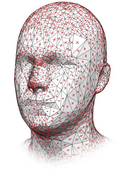
tation of e.g. an integrable direction field would be desirable as it Figure 2: The vertices and edges used to compute a ground truth
would enable the meshing algorithm to compute a perfectly aligned frame field (left) and the resulting frame field vectors for different
quad mesh, this is not strictly necessary and the algorithm will sim- sample points p′ (right).
ply produce a quad mesh that is aligned to the field as much as
possible. Thus, this approach allows us to control the structure of
the resulting mesh Q using a direction field that can be more easily
To obtain a cross field, we orthogonalize the vectors u and v for
inferred by a network operating on the input mesh T.
every face of T. To obtain a unit field, we normalize both u and v.
3.1. Representation Quadrangulation results are shown in Figure 1. As expected,
the unit direction fields (A, B) lead to meshes with significantly
The question arises as to which type of direction field should be more uniform edge lengths than their non-unit counterparts (C, D).
used to specify the desired size and orientation of the to be gener- This is of course due to the fact that a unit direction field can-
ated quads. Most commonly, this is done using a (possibly scaled) not represent varying magnitudes and therefore forces all generated
cross field [BZK09; KCPS13] or frame field [PPTS14; JFH*15; quads to be approximately the same size. Regarding the results ob-
DVPS15]. To determine which of these fields is most suitable for tained using the two non-unit fields (C, D), we observe that both of
our task at hand, we quadrangulate a given triangle mesh T us- these fields lead to meshes that closely resemble the ground truth
ing different ground truth fields and compare the resulting quad mesh (E). However, the inability of cross fields (C) to represent
meshes. More specifically, we use the Skinned Multi-Person Lin- anisotropic quad sizes introduces some distortion, which is partic-
ear Model (SMPL) [LMR*15] as a representative input shape and ularly evident in the quads located on the nose and forehead. As a
consider both unit and non-unit cross fields and frame fields. To consequence, we conclude that frame fields (D) are best suited to
obtain a mesh Q that contains only quads, we apply one iteration capture the structure found in quad meshes created by professional
of Catmull-Clark subdivision [CC78] to the quad-dominant SMPL artists.
mesh. The corresponding triangle mesh T is generated by splitting
each quad of Q into two triangles. To compute two ground truth
directions u, v for a given face f of T , we first project the barycen- 3.2. Network Architecture
ter p of f onto the surface of Q. Let p′ be the projection of p onto Motivated by the results presented in the previous section, our pro-
Q and f ′ be the face of Q that contains p′ . We use p′ to compute posed network should infer frame fields from unstructured trian-
the shortest distances d1 , d2 , d3 , d4 of p′ to the edges e1 , e2 , e3 , e4 gle meshes. Previous work on field-guided quadrangulation tech-
depicted in Figure 2 (left). The distances d1 , d2 , d3 , d4 are used to niques has highlighted the importance of aligning direction fields
interpolate between the edges of f ′ , i.e. the ground truth frame field with principal curvature directions and other local surface features
directions u and v are obtained as follows: such as sharp edges. We therefore believe that our proposed net-
d3 d1 d4 d2 work should have access to the local geometry of the input mesh
u= e1 + e3 , v = e2 + e4
d1 + d3 d1 + d3 d2 + d4 d2 + d4 T. That being said, some of the most noticeable characteristics of
© 2021 The Author(s)
Computer Graphics Forum © 2021 The Eurographics Association and John Wiley & Sons Ltd.A. Dielen, I. Lim, M. Lyon, L. Kobbelt / Learning Direction Fields for Quad Mesh Generation
1024
Global Network
concatenate
(PointNet)
nx2x2
nx1024
Local Network MLP
(SpiralNet)
nx12
Reference
Frame
Inputs Neural Network Output Frame Field Quad Mesh
Figure 3: Our network combines information from three sources to infer a frame field for a given input mesh: a global network that operates
on a point cloud representing the entire input shape, a local network that operates on patches centered around individual triangles for which
a frame is to be inferred, and a set of reference frames that describe the position and orientation of the aforementioned triangles. In the
illustration above, n denotes the number of triangles in a batch and every batch originates from a single input mesh, which allows us to run
the global network only once per batch. The network output with shape n × 2 × 2 is interpreted as a pair of 2D vectors for each of the n input
triangles. These vectors are subsequently used to guide the parametrization-based quadrangulation method described in [CBK15].
manually created quad meshes cannot be explained using local sur- was originally presented by L IM et al. in [LDCK18]. In their work,
face properties alone. An example of this are the edge loops placed L IM et al. propose to encode the neighborhood of a given vertex v0
by character artists around surface regions that are likely to deform. using a sequence of vertices [v0 , v1 , . . . , vk−1 ] that extends outwards
from v0 in a spiral manner until a predetermined number of vertices
As a consequence, our proposed network follows a dual strat- k have been enumerated. The obtained sequences are then mapped
egy that is based on the idea of combining both local and global to a new representation using either an LSTM [HS97] cell or a
shape information. More specifically, we combine the outputs of fully-connected network layer. We process sequences using fully-
a local feature network L and a global feature network G using connected layers, since the resulting network can be trained signif-
a Multi-Layer Perceptron (MLP) P. As can be seen in Figure 3, icantly faster and is only marginally less powerful. More specifi-
we also provide P with a reference frame that describes the posi- cally, the network L consists of four spiral layers. Each layer takes
tion and orientation of every input triangle. The primary purpose a sequence of k = 20 vertices as input and produces an intermediate
of these frames is to provide the network with a set of local coor- representation consisting of 16, 256, 512 and 1024 features respec-
dinate systems in which the output directions should be expressed tively. The first three layers use the spiral sequences to compute
(cf. [VCD*16, §5.2]). Specifically, the reference frame for a face f feature vectors for each mesh vertex. Since our goal is to compute
consists of the barycenter p ∈ R3 (in absolute coordinates) and the a feature vector for every triangle of the input mesh (in order to
unit vectors x f , y f , n f ∈ R3 of f , where x f corresponds to one of output a frame per face), the last layer operates on sequences that
the edges of f , n f is the normal of the supporting plane of f and are centered around the triangles. To center a sequence around a
y f = n f × x f . The output of P is a frame field represented using two given triangle, we set the first three sequence elements to the ver-
vectors u f , v f ∈ R2 for every input triangle f , where both u f and tices that make up the triangle in question and then extend this se-
v f are interpreted w.r.t. the local tangent frame defined by x f and quence using the method described in [LDCK18]. Analogous to the
y f . Since we assume a dataset of aligned shapes, we forego special global network G, we represent each input vertex using its 3D po-
consideration of rotational invariance for our reference frames and sition and normal, i.e. the first layer of L operates on sequences of
networks. 6-dimensional point features.
The global network G is based on the PointNet architecture pre-
sented by Q I et al. in [QSMG17]. Following Q I et al., we use a se- Furthermore, we subtract the center element of every sequence
quence of five fully-connected network layers with ReLU [NH10] from all remaining sequence elements. Thus, given a sequence
activation functions. However, unlike Q I et al., we do not use either [v0 , v1 , . . . , vk−1 ] of length k that is centered around a vertex v0 ,
of the two alignment networks described in [QSMG17], as they do we instead use the modified sequence [v0 , v1 −v0 , . . . , vk−1 −v0 ]. If
not appear to have a measurable effect on the performance of our the vertices in a sequence are represented using their positions and
network due to the alignment of training shapes. The input to G normals, as in the case of the vertices in the bottommost spirals, we
consists of the 32 000 vertices of the input mesh T , where each ver- apply the centering only to the positions and leave the normal vec-
tex is represented using its 3D position and normal. tors as they are. For sequences that are centered around a triangle
f , we subtract the barycenter p = 13 (v0 + v1 + v2 ), where v0 , v1 , v2
The local network L is based on the SpiralNet architecture that are the three vertices that make up f , from all sequence elements.
© 2021 The Author(s)
Computer Graphics Forum © 2021 The Eurographics Association and John Wiley & Sons Ltd.A. Dielen, I. Lim, M. Lyon, L. Kobbelt / Learning Direction Fields for Quad Mesh Generation
Q′ T′ T ′′ GTF GT
Figure 4: An example of our remeshing procedure that ensures that the edges of a mesh fed into our network are not aligned with the
corresponding ground truth quad mesh. Also shown is a visualization of the expected reconstruction error caused by our data generation
process. From left to right: the twice subdivided quad mesh Q′ , the isotropically remeshed triangle mesh T ′ , the decimated triangle mesh T ′′
that is fed into our network, a quad mesh that was reconstructed from T ′′ using a ground truth frame field (GTF), the actual ground truth
mesh (GT).
3.3. Loss Functions where both y and ŷ are assumed to be normalized. Analogous to
Equation (5), the complex cosine loss for a given triangle can then
To ensure that our loss function L penalizes both direction and size
be expressed as follows:
errors in a balanced manner, we split L into a direction loss Ld and
a size loss Ls : Lcc (u, v, û, v̂) = Lcc (u, û) + Lcc (v, v̂), (7)
L(u, v, û, v̂) = Ld (u, v, û, v̂) + Ls (u, v, û, v̂) (1)
For our size loss Ls , we compute the absolute difference between
Our direction loss is based on the von Mises distribution [MJ09] the magnitudes of the network outputs u, v and the target vectors
that approximates a normal distribution wrapped around a unit cir- û, v̂:
cle. In [BHL15], B EYER et al. use the von Mises distribution to Labs (u, v, û, v̂) = |kuk − kûk| + |kvk − kv̂k| (8)
formulate a loss for angle-based outputs θ and targets θ̂ that is in-
variant w.r.t. rotations of 2π radians: Alternatively, we also consider a relative size loss that expresses
Lvm (θ, θ̂) = 1 − eκ(cos(θ−θ̂)−1) (2) the same quantity w.r.t. the magnitudes of the target vectors û, v̂:
Since a frame can be seen as two independent directions with π kuk − kûk kvk − kv̂k
Lrel (u, v, û, v̂) = + (9)
symmetry each, we modify the loss in Equation (2) by doubling the kûk kv̂k
frequency of the cosine term. This makes the resulting loss invari-
ant w.r.t. rotations of π radians: During training, we match the network outputs u, v and ground
truth targets û, v̂ using min(L(u, v, û, v̂), L(v, u, û, v̂)). This is nec-
L2x
vm (θ, θ̂) = 1 − e
κ(cos(2(θ−θ̂))−1)
(3) essary because the network cannot know the expected order of its
outputs. Furthermore, we compute the loss for an entire batch of
Furthermore, we adapt L2x vm to vector-based network outputs and triangles using the mean of the loss function defined above.
targets using the double angle formula:
2
L2x
vm (y, ŷ) = 1 − e
κ(2(y·ŷ) −2)
, (4) 4. Dataset
where both y and ŷ are assumed to have unit length. We formulate We train our network on the meshes of the Dynamic FAUST
a per-triangle loss using the sum of two evaluations of L2x
vm : (DFAUST) [BRPB17] dataset that consists of 10 human subjects
performing a variety of motions. Strictly speaking, the DFAUST
L2x 2x 2x
vm (u, v, û, v̂) = Lvm (u, û) + Lvm (v, v̂) (5)
dataset consists of triangle meshes. However, each of these trian-
gle meshes was created by registering the quad-dominant SMPL
As an alternative, we can also formulate a direction loss that is [LMR*15] mesh with a given 3D scan and then splitting each quad
based on the representation of frame fields using unit complex num- into two triangles. As a consequence, we can recover the original
bers [KCPS13; DVPS15]. Interpreting a network output y and its quad meshes by combining the topology of the SMPL mesh with
corresponding ground truth target ŷ as unit complex numbers has the vertex coordinates of the DFAUST meshes. Subsequently ap-
the advantage that squaring both y and ŷ removes any ambiguity plying one iteration of Catmull–Clark subdivision [CC78] to the
w.r.t. their orientation, i.e. y2 = (−y)2 and similarly ŷ2 = (−ŷ)2 . recoverd meshes gives us a set of more than 40 000 meshes that
We use this property to formulate a complex cosine loss that mea- contain only quads.
sures the cosine similarity of y2 and ŷ2 :
To ensure that our network does not simply learn to align its
Lcc (y, ŷ) = 1 − (y2 · ŷ2 ), (6) outputs with the edges of the input mesh, we remesh every input
© 2021 The Author(s)
Computer Graphics Forum © 2021 The Eurographics Association and John Wiley & Sons Ltd.A. Dielen, I. Lim, M. Lyon, L. Kobbelt / Learning Direction Fields for Quad Mesh Generation
T ′′ GTF Ours GT
Figure 5: An illustration of the reconstruction error incurred by our method as a result of our data generation process. From left to right:
the remeshed network input (T ′′ ), a quad mesh reconstructed for T ′′ using the ground truth frame field (GTF), a quad mesh reconstructed
for T ′′ using our inferred frame field (Ours), the actual ground truth quad mesh (GT). As can be seen, some of the more intricate features
such as the edge loops around the fingernails cannot be reconstructed using our input triangle mesh and ground truth frame field. Despite
this, our network is able to infer similar sizes and directions.
mesh as follows: Given a ground truth quad mesh Q, we first apply fulfill these requirements and therefore select them to form our val-
two iterations of Catmull–Clark subdivision [CC78] to Q in order idation set.
to generate a higher resolution mesh Q′. Next, we triangulate Q′ to
obtain a triangle mesh T. The mesh T is then remeshed using the
isotropic remeshing method described in [BK04] and a sufficently 5. Results
small target edge length (0.004 in our experiments). As illustrated To evaluate our proposed approach, we trained the network de-
in Figure 4 (left, center left), remeshing T ensures that the result- scribed in Section 3.2 for 130 epochs on the approximately 31 000
ing mesh T ′ no longer contains any edge of Q or Q′. To reduce the training examples of the DFAUST dataset. More specifically, we
computational costs associated with processing T ′, we decimate T ′ used the Adam [KB15] optimizer with β1 = 0.9, β2 = 0.999 and
to 64 000 triangles using the incremental decimation approach pre- a learning rate of 6.25 × 10⁻⁵ . After each epoch, we reduced the
sented in [KCS98]. The resulting mesh T ′′ is shown in Figure 4 learning rate by a factor of 0.95. Furthermore, we inferred all frame
(center) and the corresponding ground truth frame field is computed fields using the network weights that performed best on our vali-
using the quad mesh Q and the method described in Section 3.1. dation set and generated the quad meshes shown throughout this
Note, that remeshing Q and then projecting the barycenters of T ′′ section using the inferred fields and the quadrangulation technique
back onto Q can reduce the quality of the generated ground truth described in [CBK15].
frame field. This can be due to a coarser triangle mesh T ′′ (offering
fewer degrees of freedom) or slight projection inaccuracies. How- As can be seen in Figure 6, our approach produces meshes that
ever, as shown in Figures 4 and 5, the quad meshes generated using capture many semantic features. The mouth, eyes and ears, for ex-
these fields still exhibit most of their original structure. ample, are all clearly defined and easily recognizable across a wide
variety of input shapes, which is of course due to the fact that the
We split the DFAUST dataset into a training, validation and test meshes used to train our network exhibit these characteristics as
set such that the test set does not contain any subject that is also well. As a consequence, our approach also generates meaningful
included in the training and/or validation set. This addresses the is- topology for other input regions, such as the upper bodies and backs
sue that many sequences include meshes where the subject assumes of human characters. For this to work, the frame fields inferred us-
an approximately neutral pose. As a consequence, the inclusion of ing our network have to induce singular vertices in appropriate lo-
the same subject in both the test and training set, would lead to a cations on the respective input shapes. We find that this works par-
significant overlap that is likely to distort our evaluation. Further- ticularly well in regions where singularities are located far apart,
more, the test set should contain both a male and a female sub- but could be improved in regions where many singularities are lo-
ject in order to be approximately representative of both the original cated in close proximity.
dataset and the range of expected network inputs. However, with-
We also evaluate our method on the FAUST [BRLB14] dataset
holding two subjects for testing purposes reduces the amount of
that contains a number of subjects not included in the larger
available training meshes significantly. Because of this, we select
DFAUST dataset. To this end, we first remesh the FAUST meshes
the male and female subjects with the smallest number of meshes,
using the method described in Section 4 and then generate frame
namely the subjects with the IDs 50009 and 50020, to make up
fields and quad meshes using our network trained on the DFAUST
our test set. For our validation set we opt to withhold a subset of se-
dataset. Results are shown in Figure 7. As can be seen, our network
quences of the remaining subjects. The withheld sequences should
generalizes quite well to these inputs.
include a sufficiently large range of motions, but should not restrict
the variety of poses in the remaining meshes too much. We find the For shapes that are increasingly different from our training set,
light_hopping_stiff and one_leg_loose sequences to we show quad meshes computed based on the inferred frame fields
© 2021 The Author(s)
Computer Graphics Forum © 2021 The Eurographics Association and John Wiley & Sons Ltd.A. Dielen, I. Lim, M. Lyon, L. Kobbelt / Learning Direction Fields for Quad Mesh Generation Figure 6: Examples of quad meshes generated using frame fields inferred by our network. As can be seen in the images above, the quad meshes generated using our approach capture many semantic features, such as the eyes, ears, and mouths of the depicted subjects. Figure 7: Examples of quad meshes generated using our approach for triangle meshes from the FAUST [BRLB14] dataset. Just as in Figure 6, our network has never seen these subjects during training. in Figure 8. On the left we show our result on a realistic model facial proportions compared to the realistic faces in DFAUST, the of a child (note that our training set consists of adults only). Here edge flow in that area is less pleasing. On the right a completely dif- the resulting quad mesh is of a similar quality to the ones obtained ferent shape is shown in the form of a mechanical component. Here on our test set. For the more stylized character (center left) with the inferred frame field is least likely to align with one a user might fairly exaggerated proportions, the quad mesh still resembles one design. Nevertheless, in certain regions the network does produce an artist might produce. For an even more unrealistic humanoid frames aligned with principal curvature directions. This suggests cartoon character (center right) the quads on the arms, legs, and that curvature information (among other shape properties) is taken upper body are well aligned. However, due to the very different into account by the network. Of course, the network is not expected © 2021 The Author(s) Computer Graphics Forum © 2021 The Eurographics Association and John Wiley & Sons Ltd.
A. Dielen, I. Lim, M. Lyon, L. Kobbelt / Learning Direction Fields for Quad Mesh Generation

Figure 8: Examples of quad meshes generated using our approach for triangle meshes with varying difference from the training set. From
left to right: a child, a stylized character, a cartoon character and a mechanical component.

 MIQ                           SIDA                           AAQ                               Ours                                  GT

Figure 9: A comparison between the methods presented by B OMMES et al. [BZK09] (MIQ), C AMPEN et al. [CIE*16] (SIDA), M ARCIAS
et al. [MPP*13] (AAQ), our approach and the corresponding ground truth mesh.

                                                                              7%                                             7%
to outperform classical frame field generation algorithms on such                                                 SIDA                                          AAQ
                                                                              6%                                             6%
mechanical parts, since it was trained on human shapes only.                                                      Ours                                          Ours
                                                                              5%                                             5%
   To assess our method in the context of other fully-automatic               4%                                             4%
quadrangulation techniques, we compare the results generated us-              3%                                             3%
ing our approach to those obtained using the curvature-based
                                                                              2%                                             2%
field synthesis methods presented by B OMMES et al. [BZK09],
                                                                              1%                                             1%
C AMPEN et al. [CIE*16] and M ARCIAS et al. [MPP*13]. For our
                                                                              0%                                             0%
comparison, we use the implementations and default parameters                   0°     5°    10°   15°    20°   25°    30°     0°     5°   10°    15°   20°    25°     30°
which were kindly provided by the respective authors. As can be
seen in Figure 9, our method generates singular vertices that are             Figure 10: Left: A comparison between the angle errors incurred
substantially better placed w.r.t. the global structure present in the        by the method presented by C AMPEN et al. [CIE*16] (SIDA) and
ground truth data. This leads to quadrangulations that are both               our method. Right: The same comparison for the method presented
cleaner and more symmetrical. The perhaps most striking differ-               by M ARCIAS et al. [MPP*13] (AAQ). As can be seen, our method
ence in overall fidelity can be observed in the faces of the depicted         generates frame fields that are significantly better aligned w.r.t. the
subjects, where our method manages to generate edge flows that                corresponding ground truth fields.
are significantly more similar to those found in manually designed
meshes.

   A quantitative comparison between the approach presented by                can be seen, our method generates frame fields that are significantly
C AMPEN et al. [CIE*16] and our method can be found in Fig-                   better aligned with the corresponding ground truth fields. Specifi-
ure 10 (left), where we visualize the distribution of angle errors            cally, more than 50 % of all frames generated using our method
incurred by the frame fields generated using both techniques. As              incur an angle error below 4.35° and more than 90 % of all frames

                                                                                                                                                     © 2021 The Author(s)
                                                                                   Computer Graphics Forum © 2021 The Eurographics Association and John Wiley & Sons Ltd.
A. Dielen, I. Lim, M. Lyon, L. Kobbelt / Learning Direction Fields for Quad Mesh Generation
Method Angle Relative Size Absolute Size
Complete Network 5.727 ± 5.295 0.125 ± 0.085 0.00106 ± 0.00069
No Global Network 6.251 ± 5.749 0.120 ± 0.087 0.00101 ± 0.00068
No Local Network 8.106 ± 7.642 0.158 ± 0.138 0.00125 ± 0.00080
Global + HKS 7.990 ± 7.557 0.155 ± 0.134 0.00123 ± 0.00080
VM + Relative 5.727 ± 5.295 0.125 ± 0.085 0.00106 ± 0.00069
VM + Absolute 5.763 ± 5.319 0.127 ± 0.091 0.00106 ± 0.00069
CC + Relative 5.943 ± 5.437 0.123 ± 0.085 0.00104 ± 0.00068
CC + Absolute 5.897 ± 5.458 0.127 ± 0.091 0.00107 ± 0.00069
Table 1: Mean errors and corresponding standard deviations on Figure 11: Our network sometimes fails to account for head
the DFAUST test set for different network variants (top) and loss rotations, which leads to meshes that capture fewer facial features
functions (bottom). Angles are given in degrees. VM and CC denote (left/center). In addition, the singularities around the navel are
the von Mises and Complex Cosine loss. almost never inferred correctly (right).
incur an angle error below 10.97°. In comparison, the method pre- the relative size loss, even though we consider all of the aforemen-
sented by C AMPEN et al. only manages to generate 17.07 % and tioned losses to be viable options.
56.71 % of all frames within the same error bounds. A comparison
with the method presented by B OMMES et al. led to similar results.
5.2. Failure Cases
For the animation-aware method presented by M ARCIAS et al.,
we used the jumping_jacks sequence of the test subject with For some of the more extreme poses in the FAUST and DFAUST
the ID 50009 to compute a direction field for the first frame in datasets, we sometimes observe frame fields that fail to account for
the sequence. The resulting quad mesh and error distributions are the rotation of the head. As a result, the edges of the generated quad
shown in Figure 9 (center) and Figure 10 (right) respectively. As meshes appear to be aligned with one of the global coordinate axes.
can be seen, the results produced by our method are closer to the Two particularly bad examples, where large parts of the generated
ground truth. faces are affected, are shown in Figure 11 (left, center). However,
the same problem can, to a lesser extend, also be seen in the two
tilted heads shown in Figure 6 (top right). Fortunately, this issue
5.1. Ablation Study does not occur too often and, if it does occur, is largely contained
To verify the validity of our network architecture, we perform an to the head of the generated mesh. A possible way to mitigate this
ablation study in which we remove different network components problem may be to make our network invariant to such rotations.
and retrain the resulting networks. Specifically, we consider the fol- Another issue arises in connection with the topology correspond-
lowing network variants: a complete network that is identical to the ing to the navel, where our network appears to be unable to infer
one presented in Section 3.2, two partial networks that do not con- the correct number of singularities. An example is shown in Fig-
tain the local and global feature networks respectively and a net- ure 11 (right). This problem is particularly surprising given the fact
work that uses Heat Kernel Signatures (HKS) [SOG09] as a drop- that these singularities are somewhat isolated and should also be
in replacement for the features computed by our local network. To comparatively easy to locate since they are centered around an um-
evaluate the performance of each of these networks, we use the bilical point (the navel). However, a closer inspection of the meshes
mean angle, mean relative size and mean absolute size errors of in our training set reveals that the singular vertices in question are
the inferred frame fields on the DFAUST test set. As can be seen often particularly bad aligned with the underlying geometry (as in
in Table 1 (top), the complete network produces the lowest overall the ground truth mesh in Figure 9), which may explain why our
angle error and outperforms the two partial networks by 9.1 % and network is unable to correctly infer these features.
41.6 %. The network based on the HKS descriptor produces an-
gles that are approximately 40 % less accurate than those predicted
by our complete network. Interestingly, the network that does not 6. Conclusion
rely on global shape information achieves a mean size error that is
We presented a novel approach for the generation of quad meshes
approximately 4 % lower than the error incurred by the complete
that is based on the idea of combining a neural network with a field-
network. This 4 % advantage, however, is more than offset by the
guided quadrangulation technique. On the one hand, a purely data-
angles inferred by this network, which are approximately 9 % less
driven approach to the direct generation of quad meshes is difficult
accurate. As a consequence, we consider the complete network that
to achieve due to topological consistency constraints that need to be
takes both global and local information into account to be overall
upheld. On the other hand, automatic model-driven methods strug-
superior.
gle to compute quadrangulations that exhibit similar characteristics
As can be seen in Table 1 (bottom), the von Mises loss performs to manually created quad meshes without proper guidance. By fol-
slightly better than the Complex Cosine loss. Similarly, the rela- lowing a hybrid approach we are able to benefit from both worlds.
tive size loss marginally outperforms its absolute counterpart. As a Our network is able to infer frame fields that resemble the align-
consequence, the results presented in the previous sections are all ment of quads found in our dataset. This rich guidance information
based on a network trained using the von Mises direction loss and can then in turn be used in robust and mature model-driven methods
© 2021 The Author(s)
Computer Graphics Forum © 2021 The Eurographics Association and John Wiley & Sons Ltd.A. Dielen, I. Lim, M. Lyon, L. Kobbelt / Learning Direction Fields for Quad Mesh Generation
that are able to guarantee the generation of correct and high-quality [CIE*16] C AMPEN, M ARCEL, I BING, M ORITZ, E BKE, H ANS -
quad meshes. Specifically, we demonstrated that our approach is C HRISTIAN, et al. “Scale-Invariant Directional Alignment of Surface
able to infer many topological features that cannot be easily gener- Parametrizations”. Computer Graphics Forum. Vol. 35. 5. Wiley Online
Library. 2016, 1–10 2, 8, 9.
ated using other techniques. The reason for this is that it is not clear
[CK14] C AMPEN, M ARCEL and KOBBELT, L EIF. “Dual Strip Weaving:
how the characteristics of manually-created quad meshes can be
Interactive Design of Quad Layouts using Elastica Strips”. ACM Trans-
derived based on a mathematical model from local surface proper- actions on Graphics 33.6 (2014), 183:1–183:10 2.
ties. Our method overcomes this problem by automatically learning
[DVPS15] D IAMANTI, O LGA, VAXMAN, A MIR, PANOZZO, DANIELE,
a map from local and global surface features to the desired orienta- and S ORKINE -H ORNUNG, O LGA. “Integrable PolyVector Fields”. ACM
tion and sizing fields. While our experiments are focused on meshes Transactions on Graphics 34.4 (2015), 1–12 2, 3, 5.
representing human characters, given suitable training data, we ex- [ESCK16] E BKE, H ANS -C HRISTIAN, S CHMIDT, PATRICK, C AMPEN,
pect that our method can be adapted to other input types. As a con- M ARCEL, and KOBBELT, L EIF. “Interactively Controlled Quad
sequence, we believe that our work represents a first step towards Remeshing of High Resolution 3D Models”. ACM Transactions on
the goal of automatically generating meshes that more closely re- Graphics 35.6 (Nov. 2016), 218:1–218:13 1, 2.
semble their manually-created counterparts. [FBT*18] FANG, X IANZHONG, BAO, H UJUN, T ONG, Y IYING, et
al. “Quadrangulation through Morse-Parameterization Hybridization”.
ACM Transactions on Graphics 37.4 (July 2018) 2.
Acknowledgements [FLWM18] F EY, M ATTHIAS, L ENSSEN, JAN E RIC, W EICHERT, F RANK,
The authors thank Jan Möbius for creating and maintaining the and M ÜLLER, H EINRICH. “SplineCNN: Fast Geometric Deep Learning
With Continuous B-Spline Kernels”. IEEE Conf. on Computer Vision
geometry processing framework OpenFlipper [MK12]. This work and Pattern Recognition. IEEE Computer Society, 2018, 869–877 2.
was partially supported by the Gottfried-Wilhelm-Leibniz Pro-
[GEvdM18] G RAHAM, B ENJAMIN, E NGELCKE, M ARTIN, and van der
gramme of the Deutsche Forschungsgemeinschaft (DFG) and by M AATEN, L AURENS. “3D Semantic Segmentation With Submanifold
the Deutsche Forschungsgemeinschaft (DFG) - 392037563. Sparse Convolutional Networks”. IEEE Conf. on Computer Vision and
Pattern Recognition. IEEE Computer Society, 2018, 9224–9232 2.
References [GSST20] G IRARD, N., S MIRNOV, D., S OLOMON, J., and TARABALKA,
Y. “Regularized Building Segmentation by Frame Field Learning”.
[AML18] ATZMON, M ATAN, M ARON, H AGGAI, and L IPMAN, YARON. IGARSS 2020 - 2020 IEEE International Geoscience and Remote Sens-
“Point convolutional neural networks by extension operators”. ACM ing Symposium. 2020, 1805–1808 2.
Transactions on Graphics 37.4 (2018), 71:1–71:12 2.
[HHF*19] H ANOCKA, R ANA, H ERTZ, A MIR, F ISH, N OA, et al.
[BBL*17] B RONSTEIN, M ICHAEL M., B RUNA, J OAN, L E C UN, YANN, “MeshCNN: a network with an edge”. ACM Transactions on Graphics
et al. “Geometric Deep Learning: Going beyond Euclidean data”. IEEE 38.4 (2019), 90:1–90:12 2.
Signal Process. Mag. 34.4 (2017), 18–42 2.
[HS97] H OCHREITER, S EPP and S CHMIDHUBER, J ÜRGEN. “Long Short-
[BCE*13] B OMMES, DAVID, C AMPEN, M ARCEL, E BKE, H ANS - Term Memory”. Neural Computation 9.8 (1997), 1735–1780 4.
C HRISTIAN, et al. “Integer-Grid Maps for Reliable Quad Meshing”.
ACM Transactions on Graphics 32.4 (2013), 1–12 1, 2. [HZN*18] H UANG, J INGWEI, Z HOU, Y ICHAO, N IESSNER, M ATTHIAS,
et al. “QuadriFlow: A Scalable and Robust Method for Quadrangula-
[BHL15] B EYER, L UCAS, H ERMANS, A LEXANDER, and L EIBE, BAS - tion”. Computer Graphics Forum (2018). ISSN: 1467-8659 2.
TIAN . “Biternion Nets: Continuous Head Pose Regression from Discrete
Training Labels”. German Conference on Pattern Recognition. Springer. [JFH*15] J IANG, T ENGFEI, FANG, X IANZHONG, H UANG, J IN, et al.
2015, 157–168 5. “Frame Field Generation through Metric Customization”. ACM Trans-
actions on Graphics 34.4 (2015), 1–11 2, 3.
[BK04] B OTSCH, M ARIO and KOBBELT, L EIF. “A Remeshing Approach
to Multiresolution Modeling”. Proceedings of the 2004 Eurograph- [JTPS15] JAKOB, W ENZEL, TARINI, M ARCO, PANOZZO, DANIELE, and
ics/ACM SIGGRAPH Symposium on Geometry Processing. 2004, 185– S ORKINE -H ORNUNG, O LGA. “Instant field-aligned meshes”. ACM
192 6. Transactions on Graphics 34.6 (2015), 189 1, 2.
[BLP*13] B OMMES, DAVID, L ÉVY, B RUNO, P IETRONI, N ICO, et al. [KB15] K INGMA, D IEDERIK P. and BA, J IMMY. “Adam: A Method for
“Quad-Mesh Generation and Processing: A Survey”. Computer Graph- Stochastic Optimization”. International Conference on Learning Repre-
ics Forum 32.6 (2013), 51–76 2. sentations. Ed. by B ENGIO, YOSHUA and L E C UN, YANN. 2015 6.
[BRLB14] B OGO, F EDERICA, ROMERO, JAVIER, L OPER, M ATTHEW, [KCPS13] K NÖPPEL, F ELIX, C RANE, K EENAN, P INKALL, U LRICH, and
and B LACK, M ICHAEL J. “FAUST: Dataset and Evaluation for 3D Mesh S CHRÖDER, P ETER. “Globally Optimal Direction Fields”. ACM Trans-
Registration”. IEEE Conf. on Computer Vision and Pattern Recognition. actions on Graphics 32.4 (2013), 1–10 2, 3, 5.
2014, 3794–3801 6, 7. [KCS98] KOBBELT, L EIF, C AMPAGNA, S WEN, and S EIDEL, H ANS -
[BRPB17] B OGO, F EDERICA, ROMERO, JAVIER, P ONS -M OLL, G ER - P ETER. “A General Framework for Mesh Decimation”. Graphics Inter-
ARD , and B LACK , M ICHAEL J. “Dynamic FAUST: Registering Human face. Vol. 98. 1998, 43–50 6.
Bodies in Motion”. IEEE Conf. on Computer Vision and Pattern Recog- [KNP07] K ÄLBERER, F ELIX, N IESER, M ATTHIAS, and P OLTHIER,
nition. 2017, 6233–6242 5. KONRAD. “QuadCover – Surface Parameterization using Branched Cov-
[BZK09] B OMMES, DAVID, Z IMMER, H ENRIK, and KOBBELT, L EIF. erings”. Computer Graphics Forum 26.3 (2007) 2.
“Mixed-Integer Quadrangulation”. ACM Transactions on Graphics 28.3 [LCBK19] LYON, M AX, C AMPEN, M ARCEL, B OMMES, DAVID, and
(2009), 1–10 1–3, 8, 9. KOBBELT, L EIF. “Parametrization Quantization with Free Boundaries
[CBK15] C AMPEN, M ARCEL, B OMMES, DAVID, and KOBBELT, L EIF. for Trimmed Quad Meshing”. ACM Transactions on Graphics 38.4
“Quantized Global Parametrization”. ACM Transactions on Graphics (2019), 1–14 2.
34.6 (2015), 1–12 1, 2, 4, 6. [LDCK18] L IM, I SAAK, D IELEN, A LEXANDER, C AMPEN, M ARCEL, and
[CC78] C ATMULL, E DWIN and C LARK, JAMES. “Recursively Generated KOBBELT, L EIF. “A Simple Approach to Intrinsic Correspondence
B-Spline Surfaces on Arbitrary Topological Meshes”. Computer-Aided Learning on Unstructured 3D Meshes”. European Conference on Com-
Design 10.6 (1978), 350–355 3, 5, 6. puter Vision. 2018 2, 4.
© 2021 The Author(s)
Computer Graphics Forum © 2021 The Eurographics Association and John Wiley & Sons Ltd.A. Dielen, I. Lim, M. Lyon, L. Kobbelt / Learning Direction Fields for Quad Mesh Generation
[LKC*20] L IU, H SUEH -T I D EREK, K IM, V LADIMIR G., C HAUDHURI, [SMKL15] S U, H ANG, M AJI, S UBHRANSU, K ALOGERAKIS, E VANGE -
S IDDHARTHA, et al. “Neural subdivision”. ACM Transactions on Graph- LOS , and L EARNED -M ILLER , E RIK G. “Multi-view Convolutional Neu-
ics 39.4 (2020), 124 2. ral Networks for 3D Shape Recognition”. IEEE International Confer-
[LMR*15] L OPER, M ATTHEW, M AHMOOD, NAUREEN, ROMERO, ence on Computer Vision. IEEE Computer Society, 2015, 945–953 2.
JAVIER, et al. “SMPL: A Skinned Multi-Person Linear Model”. ACM [SOG09] S UN, J IAN, OVSJANIKOV, M AKS, and G UIBAS, L EONIDAS. “A
Transactions on Graphics 34.6 (2015), 1–16 3, 5. Concise and Provably Informative Multi-Scale Signature based on Heat
[MBBV15] M ASCI, J ONATHAN, B OSCAINI, DAVIDE, B RONSTEIN, Diffusion”. Computer Graphics Forum. Vol. 28. 5. Wiley Online Library.
M ICHAEL M., and VANDERGHEYNST, P IERRE. “Geodesic Convolu- 2009, 1383–1392 9.
tional Neural Networks on Riemannian Manifolds”. IEEE International [TPS14] TAKAYAMA, K ENSHI, PANOZZO, DANIELE, and S ORKINE -
Conference on Computer Vision. IEEE Computer Society, 2015, 832– H ORNUNG, O LGA. “Pattern-Based Quadrangulation for N-Sided
840 2. Patches”. Computer Graphics Forum. Vol. 33. 5. Wiley Online Library.
[MBM*17] M ONTI, F EDERICO, B OSCAINI, DAVIDE, M ASCI, 2014, 177–184 2.
J ONATHAN, et al. “Geometric Deep Learning on Graphs and Manifolds [TPSS13] TAKAYAMA, K ENSHI, PANOZZO, DANIELE, S ORKINE -
Using Mixture Model CNNs”. IEEE Conf. on Computer Vision and H ORNUNG, A LEXANDER, and S ORKINE -H ORNUNG, O LGA. “Sketch-
Pattern Recognition. IEEE Computer Society, 2017, 5425–5434 2. Based Generation and Editing of Quad Meshes”. ACM Transactions on
[MGA*17] M ARON, H AGGAI, G ALUN, M EIRAV, A IGERMAN, N OAM, et Graphics 32.4 (2013), 1–8 1, 2.
al. “Convolutional neural networks on surfaces via seamless toric cov-
[TQD*19] T HOMAS, H UGUES, Q I, C HARLES R., D ESCHAUD, J EAN -
ers”. ACM Transactions on Graphics 36.4 (2017), 71:1–71:10 2. E MMANUEL, et al. “KPConv: Flexible and Deformable Convolution
[MJ09] M ARDIA, K ANTI V and J UPP, P ETER E. Directional Statistics. for Point Clouds”. IEEE International Conference on Computer Vision.
Vol. 494. John Wiley & Sons, 2009 5. IEEE, 2019, 6410–6419 2.
[MK12] M ÖBIUS, JAN and KOBBELT, L EIF. “OpenFlipper: An Open [VCD*16] VAXMAN, A MIR, C AMPEN, M ARCEL, D IAMANTI, O LGA, et
Source Geometry Processing and Rendering Framework”. Curves and al. “Directional Field Synthesis, Design, and Processing”. Computer
Surfaces. Vol. 6920. Lecture Notes in Computer Science. 2012 10. Graphics Forum. Vol. 35. 2. Wiley Online Library. 2016, 545–572 4.
[MPP*13] M ARCIAS, G IORGIO, P IETRONI, N ICO, PANOZZO, DANIELE, [WSL*19] WANG, Y UE, S UN, YONGBIN, L IU, Z IWEI, et al. “Dynamic
et al. “Animation-Aware Quadrangulation”. Computer Graphics Forum. Graph CNN for Learning on Point Clouds”. ACM Transactions on
Vol. 32. 5. Wiley Online Library. 2013, 167–175 8, 9. Graphics 38.5 (2019), 146:1–146:12 2.
[MS15] M ATURANA, DANIEL and S CHERER, S EBASTIAN A. “VoxNet: [WSLT18] WANG, P ENG -S HUAI, S UN, C HUN -Y U, L IU, YANG, and
A 3D Convolutional Neural Network for real-time object recognition”.
T ONG, X IN. “Adaptive O-CNN: a patch-based deep representation of 3D
2015 IEEE/RSJ International Conference on Intelligent Robots and Sys-
shapes”. ACM Transactions on Graphics 37.6 (2018), 217:1–217:11 2.
tems, IROS 2015, Hamburg, Germany, September 28 - October 2, 2015.
IEEE, 2015, 922–928 2. [WSS18] WANG, C HU, S AMARI, BABAK, and S IDDIQI, K ALEEM. “Local
Spectral Graph Convolution for Point Set Feature Learning”. European
[MTP*15] M ARCIAS, G IORGIO, TAKAYAMA, K ENSHI, P IETRONI, N ICO,
Conference on Computer Vision. Ed. by F ERRARI, V ITTORIO, H EBERT,
et al. “Data-Driven Interactive Quadrangulation”. ACM Transactions on
M ARTIAL, S MINCHISESCU, C RISTIAN, and W EISS, YAIR. Vol. 11208.
Graphics 34.4 (2015), 1–10 2.
Lecture Notes in Computer Science. Springer, 2018, 56–71 2.
[NH10] NAIR, V INOD and H INTON, G EOFFREY E. “Rectified Linear
Units Improve Restricted Boltzmann Machines”. International Confer- [XLZ*20] X IAO, Y UN -P ENG, L AI, Y U -K UN, Z HANG, FANG -L UE, et al.
ence on International Conference on Machine Learning. 2010 4. “A survey on deep geometry learning: From a representation perspec-
tive”. Comput. Vis. Media 6.2 (2020), 113–133 2.
[NSY09] NASRI, A, S ABIN, M ALCOM, and YASSEEN, Z AHRAA. “Filling
N-Sided Regions by Quad Meshes for Subdivision Surfaces”. Computer [ZKR*17] Z AHEER, M ANZIL, KOTTUR, S ATWIK, R AVANBAKHSH, S IA -
Graphics Forum. Vol. 28. 6. Wiley Online Library. 2009, 1644–1658 2. MAK , et al. “Deep Sets”. Advances in Neural Information Processing
Systems. Ed. by G UYON, I SABELLE, von L UXBURG, U LRIKE, B ENGIO,
[PBJW14] P ENG, C HI -H AN, BARTON, M ICHAEL, J IANG, C AIGUI, and S AMY, et al. 2017, 3391–3401 2.
W ONKA, P ETER. “Exploring quadrangulations”. ACM Transactions on
Graphics 33.1 (2014), 1–13 2.
[PFSB20] P FAFF, T OBIAS, F ORTUNATO, M EIRE, S ANCHEZ -G ONZALEZ,
A LVARO, and BATTAGLIA, P ETER W. “Learning Mesh-Based Sim-
ulation with Graph Networks”. CoRR abs/2010.03409 (2020). arXiv:
2010.03409 2.
[PPTS14] PANOZZO, DANIELE, P UPPO, E NRICO, TARINI, M ARCO,
and S ORKINE -H ORNUNG, O LGA. “Frame Fields: Anisotropic and
Non-orthogonal Cross Fields”. ACM Transactions on Graphics 33.4
(2014), 1–11 2, 3.
[QSMG17] Q I, C HARLES R, S U, H AO, M O, K AICHUN, and G UIBAS,
L EONIDAS J. “PointNet: Deep Learning on Point Sets for 3D Classifi-
cation and Segmentation”. IEEE Conf. on Computer Vision and Pattern
Recognition. 2017, 652–660 2, 4.
[QYSG17] Q I, C HARLES RUIZHONGTAI, Y I, L I, S U, H AO, and G UIBAS,
L EONIDAS J. “PointNet++: Deep Hierarchical Feature Learning on
Point Sets in a Metric Space”. Advances in Neural Information Process-
ing Systems. Ed. by G UYON, I SABELLE, von L UXBURG, U LRIKE, B EN -
GIO , S AMY , et al. 2017, 5099–5108 2.
[SBR16] S INHA, AYAN, BAI, J ING, and R AMANI, K ARTHIK. “Deep
Learning 3D Shape Surfaces Using Geometry Images”. European Con-
ference on Computer Vision. Ed. by L EIBE, BASTIAN, M ATAS, J IRI,
S EBE, N ICU, and W ELLING, M AX. Vol. 9910. Lecture Notes in Com-
puter Science. Springer, 2016, 223–240 2.
© 2021 The Author(s)
Computer Graphics Forum © 2021 The Eurographics Association and John Wiley & Sons Ltd.You can also read