A Divide et Impera Approach for 3D Shape Reconstruction from Multiple Views
←
→
Page content transcription
If your browser does not render page correctly, please read the page content below
A Divide et Impera Approach for 3D Shape Reconstruction from Multiple Views

                                           Riccardo Spezialetti*1 , David Joseph Tan2 , Alessio Tonioni2 , Keisuke Tateno2 , Federico Tombari2,3
                                                                      1
                                                                          Department of Computer Science and Engineering (DISI), University of Bologna
                                                                                                          2
                                                                                                              Google Inc.
                                                                                              3
                                                                                                  Technische Universität München
arXiv:2011.08534v2 [cs.CV] 18 Nov 2020

                                                    (a) Input Views                   (b) Ground truth            (c) Pix2Vox-A                (d) 3D-R2N2    (e) Proposed Method

                                         Figure 1. 3D Shape Reconstruction results on the ShapeNet dataset [5]. Our method successfully reconstructs the base of the chair that is
                                         visible in the input views (right part of the image) while Pix2Vox-A [59] and 3D-R2N2 [8] fail.

                                                                      Abstract                                        1. Introduction
                                                                                                                         The knowledge of the 3D structure of objects in our sur-
                                                                                                                      roundings is a necessary information for perception systems
                                                                                                                      aiming to accomplish tasks such as object interaction and
                                                                                                                      modeling. A solution to these tasks plays a key role in appli-
                                                                                                                      cations being developed – or envisioned – in the field of vir-
                                            Estimating the 3D shape of an object from a single or                     tual and augmented reality, robotic manipulation and grasp-
                                         multiple images has gained popularity thanks to the recent                   ing, rapid prototyping/reverse engineering, and autonomous
                                         breakthroughs powered by deep learning. Most approaches                      driving. Although humans can guess the 3D shape of an
                                         regress the full object shape in a canonical pose, possibly                  object from a single glance, this is a complicated task for
                                         extrapolating the occluded parts based on the learned pri-                   a computer that requires the ability to estimate the pose of
                                         ors. However, their viewpoint invariant technique often dis-                 an object and to reconstruct its 3D shape. The presence of
                                         cards the unique structures visible from the input images.                   several, sometimes non-overlapping, images sparsely taken
                                         In contrast, this paper proposes to rely on viewpoint vari-                  of an object is a common situation in scenarios such as e-
                                         ant reconstructions by merging the visible information from                  commerce, where products are advertised with randomly
                                         the given views. Our approach is divided into three steps.                   acquired images and large object databases already exist.
                                         Starting from the sparse views of the object, we first align                 Existing works can be divided into two main categories –
                                         them into a common coordinate system by estimating the                       single-view 3D object generation and multi-view 3D object
                                         relative pose between all the pairs. Then, inspired by the                   reconstruction. While the latter is a well-known traditional
                                         traditional voxel carving, we generate an occupancy grid                     computer vision problem taking into account overlapping
                                         of the object taken from the silhouette on the images and                    views around the same object, the former has only been re-
                                         their relative poses. Finally, we refine the initial reconstruc-             cently addressed successfully thanks to the availability of
                                         tion to build a clean 3D model which preserves the details                   large 3D CAD model repositories [5, 28, 40, 58] and to the
                                         from each viewpoint. To validate the proposed method, we                     introduction of deep learning based methods. Many recent
                                         perform a comprehensive evaluation on the ShapeNet ref-                      proposals rely on a neural network to reconstruct the entire
                                         erence benchmark in terms of relative pose estimation and                    shape of an object given a single image [14, 33, 37, 51, 60].
                                         3D shape reconstruction.
                                                                                                                        * Work   done while at Google.

                                                                                                                  1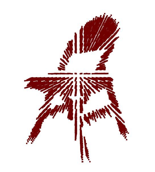
(a)                (b)                  (c)                  (d)

                                                       Optimization

                                                                                                 Occupancy

                                                                                                 Refinement
                                    Estimation

                                                        Algebraic
                                     Pairwise
                                       Pose

                                                          Pose

                                                                                                     Grid
          Set of Views                                                 Occupancy Grid                           Reconstruction
Figure 2. Given a set of views of the object, our framework (a) estimates the relative poses between pairs of images; (b) algebraically
optimize the pose of each image; (c) build an occupancy grid from poses and silhouettes; and, (d) refine the occupancy grid to reconstruct
the full model.

Although the predicted shapes are visually compelling, dif-                 tured from a limited number of views with unknown cam-
ferent structures can correspond to the occluded part of an                 era poses and in arbitrary reference systems. The complete
object, as examined in [57]; hence, determining the full 3D                 pipeline is shown in Fig. 2. Our method first constructs a
shape from a single view is an ill-posed problem. Recent                    set of all possible pairwise views and estimate the relative
works even question if the task being learned is shape esti-                poses between them through a CNN-based pose estimation.
mation or simply shape retrieval [43].                                      We then rearrange the pairs in a fully-connected graph and
                                                                            convert it to a over-determined system that can be further re-
   Multi-view 3D object reconstruction has been addressed
                                                                            fined by an algebraic pose optimization. Subsequently, we
in the past by a long line of geometry-based reconstruc-
                                                                            rely on the estimated poses to build the first rough approx-
tion techniques such as structure from motion (SfM) [34],
                                                                            imation of the 3D object reconstruction by projecting the
multi-view/photometric stereo (MVS) [16] and simultane-
                                                                            object silhouettes from every views to a shared occupancy
ous localization and mapping (SLAM) [11]. All of these
                                                                            grid. Finally, we refine the initial occupancy map with a 3D
works leverage the insight that seeing the same points of
                                                                            CNN to produce the final voxelized model estimation.
an object or a scene from different perspectives lets us un-
derstand its underlying geometry. Although these methods                       To the best of our knowledge, we are the first to pro-
are successful in handling many scenarios, they all rely on                 pose a method for multi-view shape generation from non-
feature matching that can be difficult when multiple view-                  overlapping views without the need of the poses or without
points are separated by large baselines and the amount of                   relying on the canonical orientation of the model.
textured regions is low. Practically, they require continuous
overlap between consecutive views acquired by an educated                   2. Related work
user (e.g. moving slowly and avoiding holes).
                                                                            Single-view 3D Shape Generation. Single-view shape
     Recent deep-learning based methods have been proposed                  generation methods hallucinate the invisible parts of a shape
to overcome these limitations [3, 8, 19, 41, 53, 54, 59].                   by implicitly memorizing the statistical distribution of the
Most of them rely on the assumption of either employ-                       training data. A central role for the quality of the estimated
ing the ground-truth camera poses while inferring shapes                    shape is played by the representation chosen to encode it.
[3, 8, 19, 41, 54] or predicting models oriented in a canoni-               One of the more common choice is to regress the shapes as
cal reference frame [8, 9, 59]. But neither the camera pose                 3D voxel volumes [8, 12, 15, 20, 47, 55, 56, 60] while other
nor the canonical reference frame are readily available for                 3D parametrization are indeed possible such as octrees [38,
an arbitrary object. Moreover, both single and multi-view                   42, 52], point clouds [10, 17, 29, 30], mesh [6, 14, 21, 51],
reconstruction methods tend to learn as a prior an average                  depth images [3, 37, 41], classification boundaries [7, 33]
structure of a category of objects from the training set. As a              and signed distance function [35]. Generation approaches
result, when the input object deviate significantly from the                were also explored for single-view reconstruction includ-
average structure, e.g. a chair with less than four legs (e.g.,             ing geometric primitive deformation [14, 18, 25, 46, 51], a
Fig. 1-a), the reconstruction fails badly by trying to make it              combination of Generative Adversarial Networks (GANs)
fit to the average shape. Differently, we combine deep learn-               [13] and Variational Autoencoders (VAEs) [24] in [56], and
ing with traditional computer vision wisdom to reconstruct                  re-projection consistency [22, 45, 47, 60]. However, all the
the objects and explicitly take into account the geometric                  aforementioned works are based on the assumption that the
structures that are visible in the image but are not common                 non-visible parts of the object can be hallucinated given the
in the average structure, as illustrated in Fig. 1. To do so, we            shape priors learned from the training data. Unfortunately,
propose a novel shape generation using color images cap-                    this assumption does not always holds since the occluded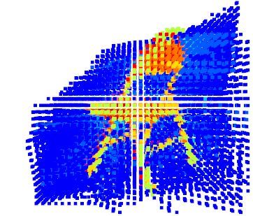
parts may not have a deterministic shape, as examined in         the input of the refiner is constructed from the visual cones
[53, 57]. Consequently, the inferred shapes tend to suffer       defined by different views. Furthermore, our pose estimator
from over smoothed surfaces without fine details. Contrary       predicts the relative pose between the pairs of views instead
to these methods, we rely on a viewpoint-variant modelling       of regressing the absolute one.
in order to learn a representation that keeps and fuse to-
gether the visible geometric details from each viewpoint.
                                                                 Shape and pose recovering. Researches have also pro-
                                                                 posed methods for simultaneous 3D shape reconstruction
Multi-view 3D Shape Generation. Extracting the 3D ge-            and camera pose estimation from a single-view [17, 40, 45].
ometry from multiple views is a well-researched topic in         Tulsiani et al. [45] regress multiple poses hypothesis for
computer vision. Methods based on SfM [4, 34, 39, 48],           each sample, forcing the learnt distribution to be similar to a
MVS [16] and SLAM [11] require to match features across          prior distribution to deal with the ambiguity of the unsuper-
images. But the matching process becomes difficult when          vised pose estimation. In contrast, Insafutdinov et al. [17]
the viewpoints are separated by wide baselines and when          train an ensemble of pose regressors and use the best model
the images are poorly textured. The dawn of deep learn-          as a teacher for knowledge distillation to a single student
ing has fostered several methods for multi-view 3D recon-        model. Finally, in [40], the pose estimation is treated as a
struction – multi-view geometric cues are exploited when         classification problem by discretizing the azimuth and ele-
training single-view prediction architectures as a supervi-      vation angles.
sory signal [17, 29, 36, 45, 60], or when training and infer-
ring multi-view systems to enrich the learned representation     3. Proposed method
by capturing view-dependent details [8, 19, 53, 54]. Unfor-
tunately, recovering this information across-views is hard if        Given a set of N images acquired from different view-
the camera poses are unknown since these methods follow          points around the same object I = {Ii }N    i=1 , the objective
the assumption that the camera pose of each image is given.      is to reconstruct the 3D shape of the object. The proposed
    Kar et al. [19] learn a model for multi-view stereopsis      method is three-fold: (1) estimation of the relative pose be-
[26]. In [54], a coarse shape generated as in [51] is refined    tween every permutation of the image pairs in I by means
iteratively by moving each vertex to the best location ac-       of a task-specific model (see Sec. 3.1); (2) graph-based rec-
cording to the features pooled from multiple views. But          tification of the bidirectional relative poses to refine them
both methods require the exact ground truth camera poses.        and calculate the absolute poses with respect to a reference
    A different way of avoiding the need for camera poses is     image (see Sec. 3.2); and, (3) reconstruction based on build-
to reconstruct the object from each view in a canonical ref-     ing an occupancy grid from the image silhouettes and the
erence system and let the network learn the view-dependent       estimated poses to then refine it through a 3D CNN (see
shape priors. Choy et al. [8] propose a unified framework        Sec. 3.3).
to create a voxelized 3D reconstruction from a sequence of
                                                                 3.1. Relative pose estimation
images (or just a single image) captured from uncalibrated
viewpoints. As soon as more views are provided to the net-          Recovering the 3D geometry of an object from a set of
work, the reconstruction is incrementally refined through a      images requires them to be correlated either through their
Recurrent Neural Networks (RNNs). However, due to the            relative or absolute poses. The absolute poses have the
permutation-variant nature of RNNs, the results can be in-       disadvantage of requiring a canonical reference coordinate
consistent and, in addition, are time-consuming.                 for every object. The canonical system needs to be unique
    An alternative way, explored in [50], is to pool only max-   for each object class and is usually handpicked, which im-
imum values. To overcome these limitations in [59], they         poses a strong constraint to the system that might not be
introduce a learned context-aware fusion module that acts        optimal for many use cases. On the other hand, predict-
on the coarse 3D volumes generated on each input images          ing the relative poses between all pairs of views removes
in parallel. In [53], Wei et al. propose to learn a generative   this constraint. Therefore, influenced by the classical 3D
model conditioned by multiple random input vectors. With         reconstruction frameworks, in our pipeline, we regress the
different random inputs, they can predict multiple plausible     relative poses between a couple of views instead of the ab-
shapes from each view to overcome the ambiguity of the           solute ones. Unlike classical 3D reconstruction, however,
non-visible parts. The final model is obtained by taking the     our approach does not require overlapping regions between
intersection of the predicted shapes on each single-view im-     the two images.
age. Similar to our work, the method proposed in [49] first         We start by arranging the set of input images in a fully
predicts a coarse shape together with the object pose from       connected graph by establishing the links of all the possible
an image using CNN then refines the coarse volume with           permutations of image pairs. We then estimate the relative
the help of a neural network. Differently, in our approach,      pose considering one image as the source (Is ) and every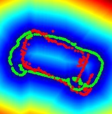
Source

                                              ResNet-18

                                                                    1024

                                                                           256

                                                                                 256
                                                Shared

                                                                                        4
                                              ResNet-18
                                                                                                         Source                  Target
        Set of Views                                                                                 Apply the predicted
                                                                                                     pose to the source
                                  Target
Figure 3. Schematic representation of our relative pose estimation architecture. A ResNet-18 based encoder that extracts image descriptors
on both the source and target images. These two embeddings are then concatenated and examined by a fully-connected network that
outputs the relative rotation between the input images.

other image as the target (It ). Defining the pose as a unit                In this case, the contour from the source and the distance
quaternion q̃ ∈ R4 , we aim at learning a deep neural net-                  transform from the target do not match.
work function N such that N (Is , It ) → R4 . A schematic
representation of the architecture is depicted in Fig. 3. We
employ a siamese ResNet-18 to extract a 1024-dimensional
deep embedding from each view independently. Then, we
concatenate the two representations and elaborate the result-
ing 2048-dimensional vector with a stack of fully connected
layers to finally regress the pose at the last layer.
                                                                                           (a)                      (b)                  (c)
3.1.1   Contour loss                                                                   Input Views                Lcontours     Lcontours + Langular

We generate the training set from the 3D model of the ob-                   Figure 4. A failure case of the contour loss, on the left (a) a couple
ject. Following [17, 45], images are created by rendering                   of input views and on the right (b-c) the ground truth contour (in
                                                                            green) and the contour oriented according to the pose estimated by
the model according to the camera projection matrix π from
                                                                            the network (in red) drawn over the corresponding distance trans-
random views with a fixed translation t∗ . By dividing them
                                                                            form. The network trained only with Lcontours (b) outputs a com-
into pairs, ground truth relative pose q ∗ from Is to It are                pletely wrong pose due to ambiguity in the distance transform.
produced. We adapt the contour loss from [32] to super-                     Adding Langular (c) solves the ambiguity and align the contours
vise the regression of the pose from the network. To find                   well.
the contours, we project the point cloud to the target im-
age and sample a sparse set of points on the object bound-
aries. The set of 3D points on the contours is denoted as
Vt := {v ∈ R3 }. Using the contours on the target image,                    3.1.2        Angular loss
we build the distance transform Dt . With the predicted pose
q̃, we define the contour loss as                                           Despite being very effective, we found out that learning a
                                                                            relative pose by aligning the object contours can easily fall
        Lcontours (q̃, Dt , Vt )                                            into local minima for objects with an elliptical structure,
                                                                            e.g. cars. Unlike [32] that uses the contour loss for small
                        h                               i
                   Dt π q̃q ∗ −1 (v − t∗ )q ∗ q̃ −1 + t∗
            X
        :=                                                    (1)
            v∈Vt
                                                                            pose changes between two images, i.e. between 4◦ and 45◦ ,
                                                                            the relative pose estimation in our work requires to handle
with q −1 being the conjugate quaternion. The function mea-                 large pose differences, mostly because we relax the con-
sures the contour’s alignment after transforming the points                 straint of having an overlapping area between the images.
from the target to source using the ground truth and from                   An example of such local minima is depicted in Fig. 4 with
the source to the target using the prediction. Although one                 a rotation of almost 180◦ . The contour loss in this case can-
can argue that we can simply take the contour points on the                 not provide a useful training signal since the front and back
source in order to avoid transforming back and forth, we                    side of the car are hardly different by just looking at the
need to consider that there are instances when the source                   contours.
and the target have a large relative pose between them and                     Taking advantage of the ground truth pose q ∗ , we can
might have contours that do not match due to occlusions.                    directly supervised the network with the angular difference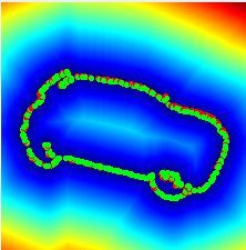
between rotations thus establishing
q ∗ q̃ −1
∗
Langular (q , q̃) := 1 − Re (2)
kq ∗ q̃ −1 k
where ‘Re’ denotes the real part of the quaternion. No-
tably, directly regressing the pose only, with Eq. 2, con-
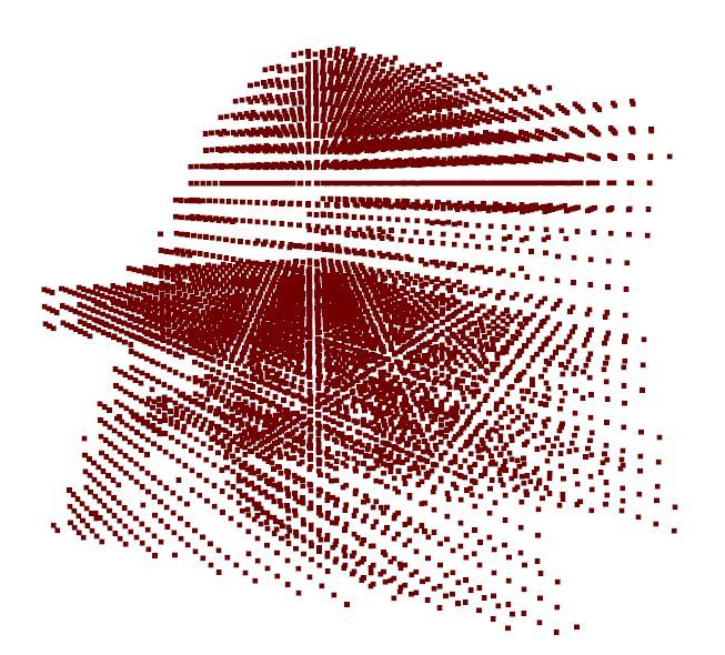
(a) (b) (c)
fuses the network especially when dealing with symmetric
Silhouette Visual Cone Rotated Visual Cone
objects like those in the ShapeNet dataset. For the same vi-
sual appearance, the ground truth rotations may be different, Figure 5. Ray casting for a single view. We show (a) silhouette of
resulting in a one-to-many mapping as pointed out in [31]. the view and (b-c) two visualization of the same visual cones – (b)
oriented according to the camera view point and (c) according to a
Using a visual proxy loss Eq. 1 is a form of regularization
different viewpoint.
that allows to overcome this issue.
3.1.3 Complete loss 3.3. Reconstruction from an occupancy grid
Finally, the loss to train our pose estimation network From the previous stage of the pipeline, we now have
the set of images I = {Ii }N i=1 with the corresponding set
Lpose = α · Langular + β · Lcontours (3) of optimized absolute poses Q = {q̂i }N i=1 with q̂1 as the
reference. Now, we proceed to reconstruct the object.
is a weighted combination of Eq. 1 and Eq. 2. In Sec. 4.1, Similar to visual hull or voxel carving [27], we want to
we discuss the relative contribution of the two components. exploit the idea of shape-from-silhouette, wherein, given a
3.2. Graph-based rectification 3D grid, the voxels outside the silhouette of at least one im-
age is carved out of the grid, ending up with the shape of
Based on the predictions from Sec. 3.1, we can build a object. However, directly using these methods is not feasi-
fully-connected graph that connects all the images through ble for two reasons. First, they usually require a large num-
the relative poses. For every pair of images, we have a bi- ber of views of the object to achieve a good reconstruction.
directional link since we can predict the pose with one of For instance, in Fig. 5, we show the problem of the recon-
them as the source while the other as target and vice versa. struction from a single view where the negative effects of
However, errors introduced from the prediction hinders us ray casting become visible when the grid is rotated. The
from directly using these poses for reconstruction. Even shape of the object becomes more detailed only when we
considering a single pair of images, there is no guarantee (greatly) increase the number of views. In our case, we must
that the relative pose estimated for one direction is the in- be able to also handle a handful of input images. Second,
verse of the other. the errors introduced from the pose estimation may generate
To solve this problem, we propose to optimize the entire small misalignment among the images that may cause the
graph and impose one relative pose per pair. Taking the carving of voxels that are on the object. Note that one of the
inspiration from the bundle adjustment [44] to fix the poses most successful applications of visual hull is a multi-camera
using least-squares, we optimize the algebraic solution of studio where all the cameras are professionally calibrated.
N X
N
Instead of the classic hard thresholding used in visual
X 2 hull, we propose to utilize an occupancy grid as the input
arg min R(q̂j ) · R(q̂i )−1 − R(q̃i,j ) (4)
q̂i to a network trained to refine this initial reconstruction. We
i=1 j=1
j6=i denote the set of silhouette as S = {Si }N i=1 , where the pixel
values are either 0 if it is outside the object or 1 if it is in the
to find q̂i which is the absolute pose of a the i-th view. Here, object. Therefore, the values of the voxels in the occupancy
q̃i,j is the predicted relative pose where the i-th image is the grid are calculated as the weighted average
source and the j-th is the target. We also convert the quater-
nions to rotation matrix through the function R(·) and as-
PN
wi · Si π q̂ · x · q̂ −1 + t∗
sume that q̂1 is the identity rotation that defines the refer- V (x) = i=1 PN (5)
i=1 wi
ence coordinate system of the absolute poses. We have veri-
fied experimentally that using the norm of difference matrix where t∗ is the ground truth camera translation, x is the cen-
in the optimization works better than the angular difference. troid of the specified voxel and wi is the weight assigned to
A more theoretical explanation can be found in [61]. Geo- the i-th view. Every voxel in the grid ranges from 0 to 1
metrically, we can interpret the difference in rotation ma- where 0 corresponds to a voxel that is not visible from any
trices in Eq. 4 as the distance between the vectors pointing view and 1 corresponds to a voxel that fall within the sil-
towards x-, y- and z-axis of the two rotations. houette of all views. In our implementation, we assume that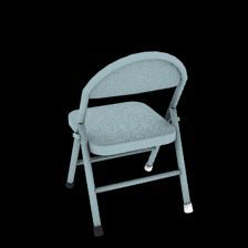
Refiner
43 × 64 Conv3D
43 × 64 Conv3D
43 × 32 Conv3D
43 × 32 Conv3D
43 × 128 Conv3D
43 × 1 Conv3D
Fully connected
Fully connected
2048
8192
Sigmoid
23 × Max Pool
23 × Max Pool
23 × Max Pool
Occupancy grid Refined Volume
32 x 32 x32 32 x 32 x32
Figure 6. Architecture of the occupancy grid refiner network that predicts the final model.
the sum of all weights is one and w2 = w3 = · · · = wN example. The network is trained with 224 × 224 RGB im-
while only w1 changes. The motivation behind this assump- ages and batch size of 24 with the loss functions weighted
tion is to give more importance to the first view – the ref- by α = 0.1 and β = 0.9. We used a fixed learning rate of
erence – since the output of the model needs to be aligned 0.001 and the Adam optimizer [23].
to this. Therefore, w1 is generally weighted higher than the To train the refiner network, we use the ground truth pose
other weights. We pick as dimension of the occupancy grid and silhouettes extracted from the images. We take a set of 5
32 × 32 × 32. views and poses per model, we randomly select one view as
The coarse representation of the occupancy grid can be reference then synthetically perturb the ground truth poses
refined with the help of deep learning a shown in Fig. 6. by a maximum of 10◦ and finally build the occupancy grid.
We employed the off-the-shelf architecture proposed in The refiner network take an occupancy grid of 32 × 32 × 32
Pix2Vox [59] to refine the raw occupancy map and predict as input and outputs a grid with the same size. We train the
the reconstruction. Differently from Pix2Vox, we use this model with the batch size of 16, the fixed learning rate of
architecture to refine an occupancy grid while their input 0.001 and the Adam optimizer [23].
is a coarse voxel map fused from single-view shape recon-
structions. To generate the ground truth voxels, we reorient
Dataset. The experiments are conducted using the 3D
the 3D model with respect to the reference view and then
models from the ShapeNetCore.v1 dataset [5]. Following
discretize it to a grid of 323 voxels. The value of the vox-
the protocol of [17, 45], we focus on the three most chal-
els in the ground truth occupancy map is either 0 (free) or
lenging categories: airplanes, cars and chairs. To render
1 (full), which is denoted as p∗i . This is differentiated from
the images for each object, we use the toolkit provided by
the predicted occupancy map p̃i .
[45], following the same data generation procedure. For
The network is trained to minimize the mean value of
each model, we render five random views with random light
the voxel-wise binary cross entropies between the predicted
source positions and random camera azimuth and eleva-
occupancy map and the reoriented ground truth model
tion, sampled uniformly from [0◦ , 360◦ ) and [−20◦ , 40◦ ],
nv respectively. To have a fair comparison, we use the same
1 X
Lrefiner = [p∗ log(p̃i ) + (1 − p∗i ) log(1 − p̃i )] (6) train and test split provided in [17, 45] for the pose estima-
nv i=1 i tion part while the split provided by [8, 59] for the shape
estimation.
where nv = 323 is the number of voxels. At test time, the
occupancy map predicted by the network is binarized by a
0.3 threshold to obtain the final reconstructed 3D model. Evaluation metrics. To measure the pose error, we use
the same metrics as Tulsiani et al. [45] which includes the
accuracy, defined as the percentage of samples for which the
4. Experimental results
error between the predicted pose and the ground truth is less
We implement all the networks using Tensorflow2.0 [1] than 30◦ , and the median error. For the shape estimation, we
while we use Ceres [2] to optimize the poses with a employ the Intersection Over Union (IoU) and the Chamfer
Cholesky solver. Distance.
Training details. The pose estimation and refiner models Evaluation methodology. To evaluate the accuracy of the
are independently trained. To train the pose network, we estimated poses, we compute the relative poses of every
render five views for each model, compute all the possible possible pairs of views given the ground truth absolute
permutations of two views and use each pair as a training poses. Then, we directly compare the predicted relative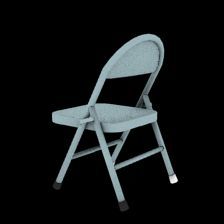
Method             Airplane       Car        Chair        Mean          Langular      Lcontours       Accuracy          Median
 GT poses [45]           0.79 10.70 0.90 7.40 0.85 11.20 0.85 9.77
 MVC [45]                0.69 14.30 0.87 5.20 0.81 7.80 0.79 9.10                  7              3              0.45            78.23
 DPCD [17]               0.75 8.20 0.86 5.00 0.86 8.10 0.82 7.10                   3              7              0.84             8.24
 Ours                     0.79   6.40   0.93 3.10 0.85   7.00   0.86 5.50          3              3              0.86             5.50
 – without optimization 0.79     6.49   0.92 3.32 0.85   7.18   0.86 5.66
 – one net all categories 0.77   6.80   0.90 3.40 0.82   6.80   0.83 5.70      Table 2. Ablation study on the angular and contour losses.
Table 1. Quantitative evaluation for pose prediction. For each
category, we report on the left the accuracy and on the right the                Method       Airplane     Car          Chair      Mean
median error.                                                                 3D-R2N2 [8]    0.585 3.77 0.851 3.58 0.575 4.21 0.670 3.86
                                                                              Pix2Vox [59]   0.723 3.20 0.876 3.54 0.612 3.77 0.737 3.50
                                                                              Ours            0.538 4.81 0.627 3.93 0.510 4.75 0.559 4.50
poses with the ground truth one.                                              – with GT poses 0.654 3.85 0.659 3.63 0.592 4.06 0.635 3.85
    For the shape evaluation, we binarize the output of the                   – in Canonical  0.732 2.92 0.874 3.51 0.648 3.39 0.751 3.28
refiner network using a threshold τr = 0.3. Then, for                       Table 3. Quantitative evaluation for shape prediction. For each
the IoU, the ground truth voxel grid is computed using the                  category, we report the average IoU on the left and the Chamfer
point cloud of the 3D model oriented by the ground truth                    distance between normalized point clouds multiplied by 100.
pose from the canonical view to the reference view. For the
Chamfer distance, we convert the predicted voxel grid into
a point cloud and compute the error against the reoriented                  our pose estimation model when training a category agnos-
ground truth cloud uniformly sampled according to [29].                     tic network rather than a different model for each category
                                                                            and applying the pose optimization. The network needs to
4.1. Pose estimation                                                        solve a much harder task in this case as testified by the small
   We compare our relative pose estimation against                          drop in performance (−0.03 in accuracy and +0.2 in the
MVC [45] as well as DPCD [17]. Both methods regress                         median error). However, even in this case, our proposal re-
the absolute camera pose from a collection of images of the                 mains competitive in terms of accuracy or lower in median
same object using a category-specific network. For MVC,                     error with respect to any competitor with the advantage of
we also report the upper bound of the method when trained                   having a single class-agnostic model while the competitor
with supervision (referred on the tables as GT poses). We                   relies on class specific models.
use the results reported by the authors in their respective
papers.                                                                     Ablation study. In Tab. 2, we report an ablation study
   Notably, both competing methods need to align the                        on the contribution of the two loss functions described in
canonical pose learned by the network to the canonical ori-                 Sec. 3.1. The values of hyperparameters α and β have been
entation of the dataset before starting the evaluation while                determined through empirical studies by considering differ-
we don’t. Moreover, both methods use different solutions                    ing combinations always summing up to 1 and measuring
to handle the problem of the shape similarity when looked                   the performance on the Shapenet validation set. Our model
from different camera views. By formulating the problem                     cannot achieve satisfactory performance when training with
as relative pose regression, our network can easily handle                  Lcontours only but training with Langular only can already pro-
these situations without using a specific mechanism.                        vide relatively good results. However, by mixing the two
   In Tab. 1, we report both the accuracy (on the left) and                 loss functions, we are able to achieve the best overall results
the median error (on the right) per category and averaged                   increasing the accuracy by 0.02 and, especially, decreasing
across all categories. We report results for our approach                   the median error by 2.77◦ .
with and without the optimization in Sec. 3.2. Even consid-
                                                                            4.2. Shape reconstruction
ering just the raw predictions, we are already able to achieve
performance better than all the competitors both in terms of                    Given an unconstrained set of views, our method is able
the average scores and the per-category performances. We                    to reconstruct the 3D model of an object aligned with one of
ascribe this result to our choice of regressing relative poses              the views provided as input. Unfortunately, there isn’t any
between views rather than the absolute pose of a single view                work in the literature that addresses the same exact settings,
with respect to an implicit reference system. The advantage                 as structure from motion methods rely on the assumption
of regressing the relative poses is particularly evident when               of having overlapping views, while most 3D reconstruction
comparing the median error where our method without op-                     methods reconstruct a model only in an arbitrary reference
timization improves the state of the art by 1.44◦ . Applying                view. Therefore, to provide some insightful comparison, we
the pose optimization described in Sec. 3.2, we further in-                 have chosen the most similar work in the literature as com-
crease the performance obtaining the best overall results.                  petitors – multi-view reconstruction solutions that do not
   In the last row of Tab. 1, we report the performance of                  require overlapping views or pose as inputs but reconstruct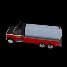
(a) Input Views                (b) Ground truth          (c) Pix2Vox-A             (d) 3D-R2N2         (e) Proposed Method

Figure 7. Comparison of multi-view reconstructions methods on the ShapeNet test set for the chair and car categories. On the left, we show
the five RGB views used as input for every method. We also report the results for the two main competitors Pix2Vox [59] and 3D-R2N2 [8].

the model only in a canonical reference view in the form of             between the reconstructions obtained by our full pipeline
a voxel grid.                                                           and the competitors on the chair and cars categories of
    In Tab. 3, we compare our work against Pix2Vox [59]                 ShapeNet test set. With the help of the estimated poses,
and 3D-R2N2 [8] using the publicly available implementa-                we are able to combine the information present in the sil-
tions. All methods take the same number of input images,                houettes and better keep some of the geometric structures
i.e. 5. For a fair comparison, we train both the pose esti-             present in the input views. Considering the chair example,
mation and the refiner networks using one model for all the             our method is the only one to correctly reconstruct the arm
categories. From the results in Tab. 3, we can see that our             rests and legs of the chair, while the competing methods ei-
approach reaches competitive results against the state-of-              ther produce detached parts in the models or fill parts that
the-art proposals such as Pix2Vox [59] and 3D-R2N2 [8].                 should be empty. Similarly, Pix2Vox [59] creates a door
We argue that the slightly inferior performances are not due            in the trunk of the truck depicted in the second row, while
to a minor accurate 3D reconstruction pipeline but due to               3D-R2N2 [8] and our method correctly leaves it empty.
the task that we are trying to solve being harder and more
realistic than the one the competitors are addressing – i.e.            5. Conclusions
arbitrarily aligned reconstruction versus canonically aligned
reconstruction. This is true even ablating the possible errors              We have proposed a novel method for 3D reconstruc-
coming from pose estimation and considering a variant of                tion from a set of sparse and non-overlapping views. To the
our model that takes ground truth poses as input, i.e. Ours             best of our knowledge, our solution is the first to propose
with GT Poses. For this model, the performance increases                a 3D reconstruction pipeline that does not require training
                                                                        models from a dataset with a predefined canonical orien-
and get closer to those of the competitors but still perform
                                                                        tation and is able to reconstruct them aligned to any ar-
slightly worse.                                                         bitrary input view. This characteristic is crucial both to
    To highlight that the worse performance are due to the              scale to real datasets as well as to apply this technology
different task we are addressing and not to deficiencies of             to common applications in the field of augmented reality
our model, we include an additional variant of our approach,            and robotics. Our pipeline is built by stand-alone compo-
i.e. Ours in Canonical. This variant uses the ground truth              nents that address recurring problems in computer vision
poses and adopts the same problem setup as the competitors              and can be easily re-used for different tasks. One of the
by predicting an occupancy grid oriented according to the               main advantages of the proposed solution is to move to-
dataset’s canonical pose. The purpose of this evaluation is             wards a more realistic solution by relaxing the requirement
                                                                        of a canonical orientation for all objects, which works well
twofold: verify if relying on the insight of having a canon-
                                                                        for academic datasets but does not scale to real world ap-
ical pose for all the train objects helps the learned model             plications. Our method yields 3D reconstructions that are
and compare only our reconstruction framework against the               on par with the state of the art in terms of accuracy while
competitors. The result shows how in the same testing con-              providing a valuable additional output in terms of estimated
dition our reconstruction pipeline can outperform the other             pose from an arbitrary viewpoint. In the future, we plan
methods. Finally, in Fig. 7, we report a visual comparison              to continue the development of our solution by relaxing the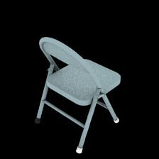
current limitations such as the fixed distance from the ori-         [14] T. Groueix, M. Fisher, V. G. Kim, B. C. Russell, and
gin of the objects and the known instrisic camera parame-                 M. Aubry. A papier-mâché approach to learning 3d surface
ters.                                                                     generation. In The IEEE Conference on Computer Vision
                                                                          and Pattern Recognition (CVPR), June 2018. 1, 2
References                                                           [15] C. Häne, S. Tulsiani, and J. Malik. Hierarchical surface pre-
                                                                          diction for 3d object reconstruction. In 2017 International
 [1] M. Abadi, A. Agarwal, P. Barham, E. Brevdo, Z. Chen,                 Conference on 3D Vision (3DV), pages 412–420. IEEE,
     C. Citro, G. S. Corrado, A. Davis, J. Dean, M. Devin, et al.         2017. 2
     Tensorflow: Large-scale machine learning on heterogeneous
                                                                     [16] R. Hartley and A. Zisserman. Multiple view geometry in
     distributed systems. arXiv preprint arXiv:1603.04467, 2016.
                                                                          computer vision. Cambridge university press, 2003. 2, 3
     6
                                                                     [17] E. Insafutdinov and A. Dosovitskiy. Unsupervised learn-
 [2] S. Agarwal, K. Mierle, and Others. Ceres solver. http:
                                                                          ing of shape and pose with differentiable point clouds. In
     //ceres-solver.org. 6
                                                                          Advances in Neural Information Processing Systems, pages
 [3] A. Arsalan Soltani, H. Huang, J. Wu, T. D. Kulkarni, and             2802–2812, 2018. 2, 3, 4, 6, 7
     J. B. Tenenbaum. Synthesizing 3d shapes via modeling
                                                                     [18] A. Kanazawa, S. Tulsiani, A. A. Efros, and J. Malik. Learn-
     multi-view depth maps and silhouettes with deep genera-
                                                                          ing category-specific mesh reconstruction from image col-
     tive networks. In Proceedings of the IEEE conference on
                                                                          lections. In Proceedings of the European Conference on
     computer vision and pattern recognition, pages 1511–1519,
                                                                          Computer Vision (ECCV), pages 371–386, 2018. 2
     2017. 2
                                                                     [19] A. Kar, C. Häne, and J. Malik. Learning a multi-view stereo
 [4] M. Brown and D. G. Lowe. Unsupervised 3d object recog-
                                                                          machine. In Advances in neural information processing sys-
     nition and reconstruction in unordered datasets. In 3DIM,
                                                                          tems, pages 365–376, 2017. 2, 3
     volume 5, pages 56–63, 2005. 3
                                                                     [20] A. Kar, S. Tulsiani, J. Carreira, and J. Malik. Category-
 [5] A. X. Chang, T. Funkhouser, L. Guibas, P. Hanrahan,
                                                                          specific object reconstruction from a single image. In Pro-
     Q. Huang, Z. Li, S. Savarese, M. Savva, S. Song, H. Su,
                                                                          ceedings of the IEEE conference on computer vision and pat-
     et al. Shapenet: An information-rich 3d model repository.
                                                                          tern recognition, pages 1966–1974, 2015. 2
     arXiv preprint arXiv:1512.03012, 2015. 1, 6
 [6] Z. Chen, A. Tagliasacchi, and H. Zhang. Bsp-net: Generat-       [21] H. Kato, Y. Ushiku, and T. Harada. Neural 3d mesh renderer.
     ing compact meshes via binary space partitioning. In Pro-            In The IEEE Conference on Computer Vision and Pattern
     ceedings of the IEEE/CVF Conference on Computer Vision               Recognition (CVPR), June 2018. 2
     and Pattern Recognition, pages 45–54, 2020. 2                   [22] H. Kato, Y. Ushiku, and T. Harada. Neural 3d mesh renderer.
 [7] Z. Chen and H. Zhang. Learning implicit fields for genera-           In Proceedings of the IEEE Conference on Computer Vision
     tive shape modeling. In Proceedings of the IEEE Conference           and Pattern Recognition, pages 3907–3916, 2018. 2
     on Computer Vision and Pattern Recognition, pages 5939–         [23] D. P. Kingma and J. Ba. Adam: A method for stochastic
     5948, 2019. 2                                                        optimization. arXiv preprint arXiv:1412.6980, 2014. 6
 [8] C. B. Choy, D. Xu, J. Gwak, K. Chen, and S. Savarese. 3d-       [24] D. P. Kingma and M. Welling. Auto-encoding variational
     r2n2: A unified approach for single and multi-view 3d object         bayes. 2014. 2
     reconstruction. In European conference on computer vision,      [25] A. Kurenkov, J. Ji, A. Garg, V. Mehta, J. Gwak, C. Choy,
     pages 628–644. Springer, 2016. 1, 2, 3, 6, 7, 8                      and S. Savarese. Deformnet: Free-form deformation network
 [9] B. Deng, K. Genova, S. Yazdani, S. Bouaziz, G. Hinton, and           for 3d shape reconstruction from a single image. In 2018
     A. Tagliasacchi. Cvxnet: Learnable convex decomposition.             IEEE Winter Conference on Applications of Computer Vision
     In Proceedings of the IEEE/CVF Conference on Computer                (WACV), pages 858–866. IEEE, 2018. 2
     Vision and Pattern Recognition, pages 31–44, 2020. 2            [26] K. N. Kutulakos and S. M. Seitz. A theory of shape by
[10] H. Fan, H. Su, and L. J. Guibas. A point set generation net-         space carving. International journal of computer vision,
     work for 3d object reconstruction from a single image. In The        38(3):199–218, 2000. 3
     IEEE Conference on Computer Vision and Pattern Recogni-         [27] A. Laurentini. The visual hull concept for silhouette-based
     tion (CVPR), July 2017. 2                                            image understanding. IEEE Transactions on pattern analysis
[11] J. Fuentes-Pacheco, J. Ruiz-Ascencio, and J. M. Rendón-             and machine intelligence, 16(2):150–162, 1994. 5
     Mancha. Visual simultaneous localization and mapping: a         [28] J. J. Lim, H. Pirsiavash, and A. Torralba. Parsing ikea ob-
     survey. Artificial Intelligence Review, 43(1):55–81, 2015. 2,        jects: Fine pose estimation. In Proceedings of the IEEE
     3                                                                    International Conference on Computer Vision, pages 2992–
[12] R. Girdhar, D. F. Fouhey, M. Rodriguez, and A. Gupta.                2999, 2013. 1
     Learning a predictable and generative vector representation     [29] C.-H. Lin, C. Kong, and S. Lucey. Learning efficient point
     for objects. In European Conference on Computer Vision,              cloud generation for dense 3d object reconstruction. In
     pages 484–499. Springer, 2016. 2                                     Thirty-Second AAAI Conference on Artificial Intelligence,
[13] I. Goodfellow, J. Pouget-Abadie, M. Mirza, B. Xu,                    2018. 2, 3, 7
     D. Warde-Farley, S. Ozair, A. Courville, and Y. Bengio. Gen-    [30] P. Mandikal, K. L. Navaneet, M. Agarwal, and R. V. Babu.
     erative adversarial nets. In Advances in neural information          3D-LMNet: Latent embedding matching for accurate and
     processing systems, pages 2672–2680, 2014. 2                         diverse 3d point cloud reconstruction from a single image.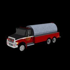
In Proceedings of the British Machine Vision Conference         [44] B. Triggs, P. F. McLauchlan, R. I. Hartley, and A. W. Fitzgib-
       (BMVC), 2018. 2                                                      bon. Bundle adjustment—a modern synthesis. In Inter-
[31]   F. Manhardt, D. M. Arroyo, C. Rupprecht, B. Busam,                   national workshop on vision algorithms, pages 298–372.
       T. Birdal, N. Navab, and F. Tombari. Explaining the am-              Springer, 1999. 5
       biguity of object detection and 6d pose from visual data. In    [45] S. Tulsiani, A. A. Efros, and J. Malik. Multi-view consis-
       Proceedings of the IEEE International Conference on Com-             tency as supervisory signal for learning shape and pose pre-
       puter Vision, pages 6841–6850, 2019. 5                               diction. In Proceedings of the IEEE Conference on Computer
[32]   F. Manhardt, W. Kehl, N. Navab, and F. Tombari. Deep                 Vision and Pattern Recognition, pages 2897–2905, 2018. 2,
       model-based 6d pose refinement in rgb. In Proceedings of the         3, 4, 6, 7
       European Conference on Computer Vision (ECCV), pages            [46] S. Tulsiani, A. Kar, J. Carreira, and J. Malik. Learning
       800–815, 2018. 4                                                     category-specific deformable 3d models for object recon-
[33]   L. Mescheder, M. Oechsle, M. Niemeyer, S. Nowozin, and               struction. IEEE transactions on pattern analysis and ma-
       A. Geiger. Occupancy networks: Learning 3d reconstruction            chine intelligence, 39(4):719–731, 2016. 2
       in function space. In Proceedings of the IEEE Conference        [47] S. Tulsiani, T. Zhou, A. A. Efros, and J. Malik. Multi-view
       on Computer Vision and Pattern Recognition, pages 4460–              supervision for single-view reconstruction via differentiable
       4470, 2019. 1, 2                                                     ray consistency. In Proceedings of the IEEE conference on
[34]   O. Özyeşil, V. Voroninski, R. Basri, and A. Singer. A sur-         computer vision and pattern recognition, pages 2626–2634,
       vey of structure from motion*. Acta Numerica, 26:305–364,            2017. 2
       2017. 2, 3                                                      [48] S. Ullman. The interpretation of structure from motion. Pro-
[35]   J. J. Park, P. Florence, J. Straub, R. Newcombe, and S. Love-        ceedings of the Royal Society of London. Series B. Biological
       grove. Deepsdf: Learning continuous signed distance func-            Sciences, 203(1153):405–426, 1979. 3
       tions for shape representation. In Proceedings of the IEEE      [49] H. Wang, J. Yang, W. Liang, and X. Tong. Deep single-view
       Conference on Computer Vision and Pattern Recognition,               3d object reconstruction with visual hull embedding. In Pro-
       pages 165–174, 2019. 2                                               ceedings of the AAAI Conference on Artificial Intelligence,
[36]   D. J. Rezende, S. A. Eslami, S. Mohamed, P. Battaglia,               volume 33, pages 8941–8948, 2019. 3
       M. Jaderberg, and N. Heess. Unsupervised learning of 3d         [50] M. Wang, L. Wang, and Y. Fang. 3densinet: A robust neural
       structure from images. In Advances in Neural Information             network architecture towards 3d volumetric object prediction
       Processing Systems, pages 4996–5004, 2016. 3                         from 2d image. In Proceedings of the 25th ACM interna-
[37]   S. R. Richter and S. Roth. Matryoshka networks: Predicting           tional conference on Multimedia, pages 961–969, 2017. 3
       3d geometry via nested shape layers. In The IEEE Confer-        [51] N. Wang, Y. Zhang, Z. Li, Y. Fu, W. Liu, and Y.-G. Jiang.
       ence on Computer Vision and Pattern Recognition (CVPR),              Pixel2mesh: Generating 3d mesh models from single rgb im-
       June 2018. 1, 2                                                      ages. In Proceedings of the European Conference on Com-
[38]   G. Riegler, A. Osman Ulusoy, and A. Geiger. Octnet: Learn-           puter Vision (ECCV), pages 52–67, 2018. 1, 2, 3
       ing deep 3d representations at high resolutions. In Proceed-    [52] P.-S. Wang, Y. Liu, Y.-X. Guo, C.-Y. Sun, and X. Tong.
       ings of the IEEE Conference on Computer Vision and Pattern           O-cnn: Octree-based convolutional neural networks for 3d
       Recognition, pages 3577–3586, 2017. 2                                shape analysis. ACM Transactions on Graphics (TOG),
[39]   N. Snavely, S. M. Seitz, and R. Szeliski. Photo tourism:             36(4):72, 2017. 2
       exploring photo collections in 3d. In ACM transactions on       [53] Y. Wei, S. Liu, W. Zhao, and J. Lu. Conditional single-
       graphics (TOG), volume 25, pages 835–846. ACM, 2006. 3               view shape generation for multi-view stereo reconstruction.
[40]   X. Sun, J. Wu, X. Zhang, Z. Zhang, C. Zhang, T. Xue, J. B.           In Proceedings of the IEEE Conference on Computer Vision
       Tenenbaum, and W. T. Freeman. Pix3d: Dataset and methods             and Pattern Recognition, pages 9651–9660, 2019. 2, 3
       for single-image 3d shape modeling. In Proceedings of the       [54] C. Wen, Y. Zhang, Z. Li, and Y. Fu. Pixel2mesh++: Multi-
       IEEE Conference on Computer Vision and Pattern Recogni-              view 3d mesh generation via deformation. In Proceedings
       tion, pages 2974–2983, 2018. 1, 3                                    of the IEEE International Conference on Computer Vision,
[41]   M. Tatarchenko, A. Dosovitskiy, and T. Brox. Multi-view 3d           pages 1042–1051, 2019. 2, 3
       models from single images with a convolutional network. In      [55] J. Wu, Y. Wang, T. Xue, X. Sun, B. Freeman, and J. Tenen-
       European Conference on Computer Vision, pages 322–337.               baum. Marrnet: 3d shape reconstruction via 2.5 d sketches.
       Springer, 2016. 2                                                    In Advances in neural information processing systems, pages
[42]   M. Tatarchenko, A. Dosovitskiy, and T. Brox. Octree gen-             540–550, 2017. 2
       erating networks: Efficient convolutional architectures for     [56] J. Wu, C. Zhang, T. Xue, B. Freeman, and J. Tenenbaum.
       high-resolution 3d outputs. In Proceedings of the IEEE Inter-        Learning a probabilistic latent space of object shapes via 3d
       national Conference on Computer Vision, pages 2088–2096,             generative-adversarial modeling. In Advances in neural in-
       2017. 2                                                              formation processing systems, pages 82–90, 2016. 2
[43]   M. Tatarchenko, S. R. Richter, R. Ranftl, Z. Li, V. Koltun,     [57] J. Wu, C. Zhang, X. Zhang, Z. Zhang, W. T. Freeman, and
       and T. Brox. What do single-view 3d reconstruction net-              J. B. Tenenbaum. Learning shape priors for single-view 3d
       works learn?        In Proceedings of the IEEE Conference            completion and reconstruction. In Proceedings of the Euro-
       on Computer Vision and Pattern Recognition, pages 3405–              pean Conference on Computer Vision (ECCV), pages 646–
       3414, 2019. 2                                                        662, 2018. 2, 3
[58] Y. Xiang, R. Mottaghi, and S. Savarese. Beyond pascal: A
benchmark for 3d object detection in the wild. In IEEE win-
ter conference on applications of computer vision, pages 75–
82. IEEE, 2014. 1
[59] H. Xie, H. Yao, X. Sun, S. Zhou, and S. Zhang. Pix2vox:
Context-aware 3d reconstruction from single and multi-view
images. In The IEEE International Conference on Computer
Vision (ICCV), October 2019. 1, 2, 3, 6, 7, 8
[60] X. Yan, J. Yang, E. Yumer, Y. Guo, and H. Lee. Perspective
transformer nets: Learning single-view 3d object reconstruc-
tion without 3d supervision. In Advances in Neural Informa-
tion Processing Systems, pages 1696–1704, 2016. 1, 2, 3
[61] Y. Zhou, C. Barnes, J. Lu, J. Yang, and H. Li. On the conti-
nuity of rotation representations in neural networks. In Pro-
ceedings of the IEEE Conference on Computer Vision and
Pattern Recognition, pages 5745–5753, 2019. 5A Divide et Impera Approach for 3D Shape Reconstruction from Multiple Views
(Supplementary Materials)
Due to the page constraints of the main submission, our error for our pose estimation network is around 5◦ , it is fair
supplementary material includes additional results and ab- to assume that the noise in the estimated pose will not dra-
lation studies to help understand the proposed method. matically affect the final reconstruction.
1. Shape reconstruction 2. Qualitative results of our pose estimation
In this section, we provide additional experiments on the We provide in Fig. 2 the qualitative results to show the
quality of the shape reconstructed by our method. Partic- effectiveness of our pose estimation network. We compare
ularly, we study how the reconstructions can be improved the results obtained by estimating the relative pose for pairs
when more views are available. We then focus on the ro- of images taken from the objects belonging to different cat-
bustness of the refiner when the poses used to build the oc- egories in different poses.
cupancy grid are affected by a significant amount of noise. Given the input pairs shown in the first and second
In both experiments, we use the Chamfer Distance as met- columns of Fig. 2, the third column in the figure compares
ric. the point clouds of the CAD model aligned according to
the ground truth pose and the predicted one, in green and
4.33
4.28
4.33
4.28 red, respectively. Here, the alignment between the two
4.24
4.24
4.19 4.19 point clouds verifies the accuracy we achieved in the main
Chamfer Distance
Chamfer Distance
4.15 4.15
4.1
4.06
4.1
4.06
manuscript.
4.01
3.97
4.01
3.97 To provide a better visualization of the quality of the
3.92
3.92
3.88 3.88
3.83
estimated poses, the figures in the last column encode the
3.83
3.79
3.75
3.79
3.75
misalignment error computed as the per point Euclidean
3.7
3 5 7 9 11 13 15 17 19
3.7
0 5 10 15 20 25 30 Distance between the point cloud rotated according to the
Number of views Noise in degrees
(a) (b)
ground truth matrix and the point cloud oriented with the
predicted one. Note that the errors are normalized according
Figure 1. The Chamfer Distance computed on the ShapeNet test- to the maximum error. From these results, we can observe
ing set with different pre-conditions – (a) effects of using a dif- that our network produces good alignments even in cases
ferent number of views as input; and, (b) robustness of the refiner where the rotation between the source and target image is
network to the noise in the poses.
large such as the first, fourth and fifth row (low overlapping
area between views). This is clearly evident in the point
Fig. 1(a) illustrates that, as we increase the number of clouds in column (c) that almost completely overlap and the
views when constructing the occupancy grid, the Chamfer misalignment error in column (d) which is consistently low
Distance between the final reconstruction and the ground for most points.
truth decreases. Increasing the number of views from 5 to
10 give us the most significant boost in the performance. 3. Qualitative results of our shape reconstruc-
The goal of the experiment, whose results are depicted tion
in Fig. 1(b), is to highlight how the noise in the estimated
poses affects the final reconstruction. For that reason, we In Fig. 3, we show more qualitative results of the recon-
build the occupancy grid perturbing the ground truth poses struction obtained by our pipeline for the three categories
with a random amount of noise between zero and a maxi- considered: airplanes, cars and chairs.
mum value. We varied the value of maximum random noise Due to the view-dependent reconstruction, the voxel grid
between the range 0◦ to 30◦ . Fig. 1(b) shows that, even obtained to supervise our model in training has a lower spa-
with a maximum amount of noise in the poses of 15◦ , the tial resolution compared to the voxel grid available in the
performance declines gracefully. Notably, since the median ShapeNet dataset [1]. Indeed, to get a voxel grid w.r.t.
1Input Views Ground truth Pix2Vox-A 3D-R2N2 Our Method
1.0
0.5
0.0
1.0
0.5
0.0
Figure 3. Comparison of multi-view reconstructions methods on
the ShapeNet test set for the chair, car and plane category. On the
1.0
left, we show the 5 RGB views used as input for every method. We
also report the results for the two main competitors Pix2Vox [3]
0.5
and 3D-R2N2 [2].
0.0
a b c d
Figure 2. Qualitative results for the pose estimation network. We the input views (Ours); and, the one that always reconstruct
show on the left (a, b) the source and target input image, on the a model in a canonical reference frame (Ours Canonical).
right (c) the CAD model point cloud, in green, oriented according The purpose of this comparison is to clarify the performance
to the ground truth pose, and the same point cloud, in red, oriented of the second stage of our method, which is composed of
with the pose predicted by our method. In the last column (d), building the occupancy grid and the refiner network. For
we visualize the normalized misalignment error between the two Ours Canonical, we first build an occupancy grid oriented
models as a heat map ranging from blue (perfect alignment) to red as the canonical orientation of the ShapeNet dataset, then
(maximum misalignment).
we refine this volume using the refiner network. As already
pointed out in section Sec. 3, to supervise our network, for
the reference view, we first align the point cloud of the (Ours Canonical), we use as ground truth the voxel grid
CAD model to the reference view, then we voxelize it in available from the ShapeNet dataset. When comparing the
a 32 × 32 × 32 grid. As a result, the predicted shapes have a reconstruction of Ours Canonical to Ours, we can see how
smaller spatial resolution since they need to be aligned with the reconstruction on a fixed reference frame results in more
the input RGB images, and therefore our refiner model out- detailed and smooth models. We ascribe this difference to
puts a shape with the same lower spatial resolution. This the task learned being simpler than reconstruction w.r.t. an
difference is even more clear if we look at the reconstruc- arbitrary viewpoint. When comparing the reconstructions
tion in Sec. 4 where Ours Canonical is trained using instead of Ours Canonical to those of the competing methods, we
the voxel grid available in ShapeNet. can see once again how our method is able to obtain a sim-
Considering the reconstruction of chairs, trucks and ilar quality of the reconstructed shape, while, at the same
planes in Fig. 3, our method correctly approximate the time, maintaining the fine details like: the legs and arm rests
shape of the models while, at the same time, keeps some in the chair, the exhaust pipes in the truck or the propellers
of the fine details like the flash light and the rear floor for in the plane. We believe that these results clearly show how
the truck in the second row. our 3D reconstruction from silhouettes projected in an oc-
cupancy grid is as effective (or more) than the alternatives
4. Qualitative Results using the canonical ori- proposed in the literature. However, reconstruction w.r.t. an
arbitrary reference frame is a much harder task and this is
entation
reflected in slightly less detailed models for Our pipeline
This section compares the generated shapes of two vari- without the canonical frame reconstruction. We will pro-
ants of our reconstruction pipeline – the standard one recon- vide more details on how the reconstruction change with
structing in an arbitrary reference frame aligned with one of respect to the view choose as reference in Sec. 5GT Pix2Vox-A 3D-R2N2 Ours Ours Canonical
Figure 4. Comparison of multi-view reconstructions methods on
the ShapeNet test set. On the left, we show the ground truth
voxel grid. We also report the results for the two main competitors
Pix2Vox [3] and 3D-R2N2 [2].
5. Qualitative results when changing the refer-
ence view
Here, we show how our pipeline is able to reconstruct
different models with respect to the reference view consid-
ered when building the occupancy grid. First of all, we
would like to point out that our method can correctly re-
construct a model that is nicely aligned to each of the views
when it is selected as reference. Secondly, we want high-
light how the fine details on the reconstructions depends on
how well the corresponding details are visible in the orig-
inal reference image. For example, the reconstruction of
the legs of the first chair is more detailed when selecting as
reference view one of the two rightmost one where the ge-
ometrical structure of the leg is cleanly visible. The same
consideration can be extended to the second chair where the
shape that mostly highlights the peculiar shape of the back-
rest is the one obtained when considering as reference the Figure 5. Comparison of multi-view reconstructions methods on
third view. the ShapeNet test set for the chair category. In each column, we
depict the voxel grid produced using a different reference view.
References
[1] A. X. Chang, T. Funkhouser, L. Guibas, P. Hanrahan,
Q. Huang, Z. Li, S. Savarese, M. Savva, S. Song, H. Su, et al.
Shapenet: An information-rich 3d model repository. arXiv
preprint arXiv:1512.03012, 2015. 2
[2] C. B. Choy, D. Xu, J. Gwak, K. Chen, and S. Savarese. 3d-
r2n2: A unified approach for single and multi-view 3d object
reconstruction. In European conference on computer vision,
pages 628–644. Springer, 2016. 2, 3
[3] H. Xie, H. Yao, X. Sun, S. Zhou, and S. Zhang. Pix2vox:
Context-aware 3d reconstruction from single and multi-view
images. In The IEEE International Conference on Computer
Vision (ICCV), October 2019. 2, 3You can also read