CO2 Product Guide 2021 - for Refrigeration Applications

Page created by Leslie Meyer
 
CONTINUE READING
CO2 Product Guide 2021 - for Refrigeration Applications
CO2 Product Guide 2021
    for Refrigeration Applications
CO2 Product Guide 2021 - for Refrigeration Applications
Table of contents

     Introduction
       1. Criteria for refrigerant selection                                          4
       2. Properties of R744                                                          4
       3. An Introduction of transcritical operation                                  7
       4. Behaviour in the reference cycle                                            8
       5. R744 hazards                                                                9
       6. Comparison of R744 with other refrigerants                                  10
       7. Advantage and disadvantage of R744 as a refrigerant                         12

     Products
       ZO & ZOD Copeland™ scroll compressor range for CO2-subcritical refrigeration   13
       Copeland semi-hermetic compressor with compressor electronics technology for
                                                                                      15
       R744-transcritical applications
       Copeland semi-hermetic compressor with compressor electronics technology for
                                                                                      18
       R744-subcritical applications requiring high standstill pressures (90 bar)
       Copeland outdoor refrigeration units for R744 transcritical applications       20
       Electronic expansion valves series CX2                                         22
       High-pressure electrical controls valves series CV4-7                          23
       Electrical control valves series EX4-8                                         25
       Universal driver modules series EXD-U02                                        28
       Superheat controllers series EXD-SH1/2                                         29
       2-way solenoid valves series 200 RH                                            32
       Coils ESC and cable assemblies                                                 33
       Pressure transmitter PT5N                                                      34
       Pressure Controls Series CS1                                                   36
       Pressure controls series CS3                                                   37
       Filter driers series ADK                                                       40
       Filter drier shells series FDH                                                 41
       Moisture / Liquid indicators series CIA                                        42
       OM4 and OM5 TraxOil oil management                                             43
       Electronic oil level monitoring traxOil™ OW4 and OW5                           47
       Level watch LW4 and LW5 liquid level control                                   49
       Ball valves series CVE/CVS                                                     51

2
CO2 Product Guide 2021 - for Refrigeration Applications
Introduction
Currently it is not an easy matter for decision makers in commercial refrigeration to make a definite choice of refrigerants
and system type. For the last decade, many refrigerant options and system architectures have appeared both on paper and
in practice. The sector has been in the environmental spotlight in recent years, especially as leakage studies have revealed
the true effects of HFC emissions in centralised systems. Considerable reductions in emissions are certainly possible,
but they do require changes.

Emerson conducted a study on this topic, comparing various options. The conclusion was clear, there is no best option for
key criteria, environment, cost and power consumption. A tool, The Right Balance calculator, is available on the Emerson
website to enable customers to make tailored comparisons. Different options are likely to develop in the next decade
depending on regional trends, legislation, genuine green initiatives and green image enhancement.

R744 (CO2) is a leading option for environmental reasons, and it can be a winner for power consumption as developments
of component technology and application methods continue to reveal potential performance gains. Good experience
has been gained with different system configurations over many years, particularly in central and northern Europe. The
confidence resulting from this experience ensures that CO2 will be a long-term option in the foreseeable future.

CO2 is termed a “Natural Refrigerant” because it exists in the natural environment. Released into the atmosphere from
refrigeration systems has a negligible effect compared to other CO2 sources that are driving the global warming debate.
As a refrigerant, it is a manufactured product that conforms to strict purity specifications. Its physical properties require
special handling. The system pressures are much higher than in conventional systems, and all the components are designed
accordingly. Today there is no difficulty in sourcing all the necessary equipment. High investment costs were characteristic
of early CO2 projects, but these costs are now on a downward trend. The refrigerant itself is a fraction of the cost of some of
the specialty HFCs.

                                                                                                                                  3
CO2 Product Guide 2021 - for Refrigeration Applications
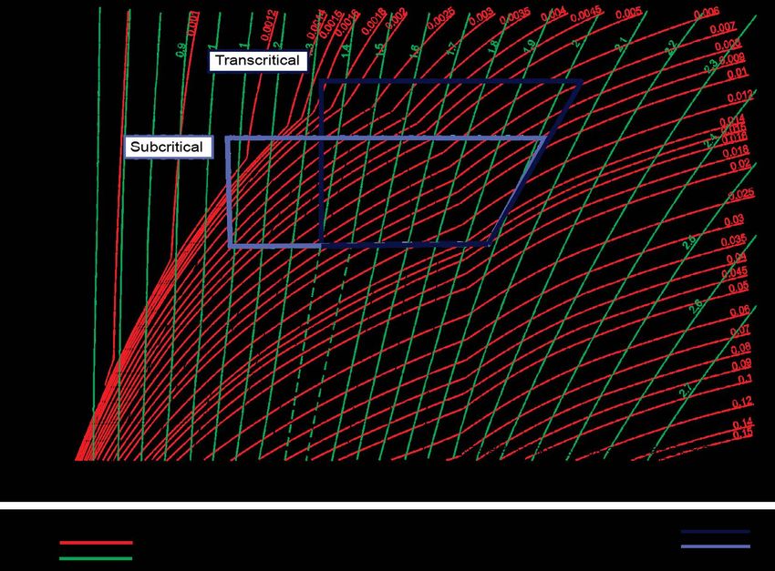
CO2 Basics and considerations as a refrigerant
    This chapter introduces carbon dioxide as a refrigerant, describes its properties and compares it to other refrigerants,
    both traditional and new. It outlines the hazards of CO2 and explains why CO2 refrigeration systems differ from
    conventional systems.
    Section 1. Criteria for refrigerant selection
    Various criteria should be considered when selecting properties, safety, environmental impact, ease of use, and availability
    of components and expertise.
    The following table lists the criteria that are important when selecting a refrigerant and shows how well R744 meets these
    criteria. More detail is provided later in this chapter.

    R744 meets the demand for a natural refrigerant with a low global warming impact, but presents challenges in both its
    application and handling

    Table 1. How R744 meets different conditions and criteria

                                 Criteria                                            How well does R744 meet the criteria?

        Cooling capacity                                            Significantly higher volumetric capacity than conventional refrigerants

        Efficiency                                                  Efficiency depends on system type and ambient temperature

                                                                    Operating and standstill pressures significantly higher than for all other
        Operating conditions
                                                                    common retail refrigeration refrigerants
                                                                    Global Warming Potential (GWP) = 1, significantly lower than for commonly
        Environmental properties
                                                                    used HFCs

        Availability of refrigerant                                 Varies globally but generally available

                                                                    Many components are different to those used on HFC retail systems, but these
        Availability of system components
                                                                    are now generally available
                                                                    Varies globally but generally low; engineers must have a good understanding
        Availability of competent engineers and technicians         of basic refrigeration and good refrigeration practice and will require further
                                                                    training for R744

        Cost                                                        Refrigerant cost lower than for HFCs, but system costs are generally higher

                                                                    Low toxicity and nonflammable: high-pressures and associated hazards present
        Safety
                                                                    additional challenges. It is asphyxiating even at low concentration

        Ease of use                                                 High-pressure and low critical point drive the need for more complex systems

        Availability of appropriate standards                       Safety Standards EN378 & ISO 51491 include R744

        Composition                                                 Single molecule, no temperature glide in subcritical operations

        Suitability as a retrofit refrigerant                       Not suitable due to higher pressures
    1
      EN378 Refrigerating systems and heat pumps – Safety and environmental requirements
    ISO 5149 mechanical refrigerating systems used for cooling and heating - Safety requirements.

    Section 2. Properties of R744
    Carbon dioxide is a naturally occurring substance – the atmosphere is comprised of approximately 0.04% CO2 (370 ppm).
    It is produced during respiration by most living organisms and is absorbed by plants. It is also produced during many
    industrial processes, in particular when fossil fuels such as coal, gas or oil are burned to generate power or drive vehicles.

    The triple point of carbon dioxide is high and the critical point is low compared to other refrigerants. The chart in figure
    3 shows the triple point and the critical point on a phase diagram.

    The triple point occurs at 4.2 bar g and -57°C, below this point there is no liquid phase. At atmospheric pressure (0 bar g),
    solid R744 sublimes directly to a gas. Solid R744 will have a surface temperature of -78°C. If R744 is at a pressure higher
    than the triple point and it reduces to a pressure below the triple point (for example to atmospheric pressure), it will
    deposit directly to solid. This can occur when charging an evacuated refrigeration system with liquid R744 for example.
    Solid R744 is also known as dry ice.

4
CO2 Product Guide 2021 - for Refrigeration Applications
The critical point occurs at 31°C, which is below typical
                                                                        The critical point is the condition at which the liquid
system condensing temperatures for part or all of the year,
                                                                        and gas densities are the same. Above this point
depending on the climate. Above the critical point the
                                                                        distinct liquid and gas phases do not exist.
refrigerant is a transcritical fluid. There is no phase change
when heat is removed from a transcritical fluid while it is
                                                                        The triple point is the condition at which solid, liquid
above the critical pressure and temperature.
                                                                        and gas co-exist. The glossary has a full explanation
                                                                        of the terms used in this section.
In a refrigeration system transcritical R744 will not
condense until the pressure has dropped below the ciritical
pressure. No other commonly used refrigerant has such a
low critical temperature so they always condense as heat is         The boundaries of the transcritical fluid region are:
removed on the high side of the system.
                                                                    •    The critical temperature (31°C) to the sub-cooled
                                                                         liquid region
                                                                    •    The critical pressure (72.8 bar g) to the superheated
                                                                         gas region

                                                                    Table 2 on page 6 compares the basic properties of R744 with different
                                                                    refrigerants which are commonly used in the retail sector

                  10 000
                                    solid

                      1 000                                                                    transcritical
                                                           liquid                              fluid
        p (bar abs)

                       100
                                                                                  critical point
                                                                                  (31°C / 72.8 bar g)

                                                                          gas
                                     triple point
                                     (-57°C / 4.2 bar g)

                         1
                              -70           -40              -10        -20              -50              -80                110
                                                                         T (°C)

Figure 3. R744 / CO2 phase diagram

                                                                                                                                             5
CO2 Product Guide 2021 - for Refrigeration Applications
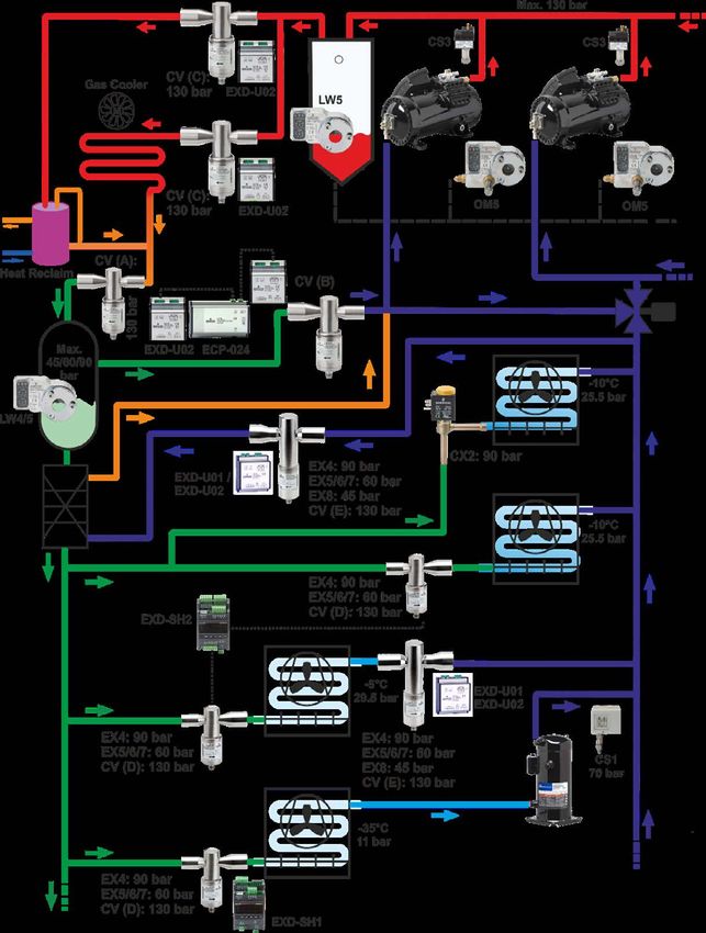
The pressure enthalpy chart in figure 4 shows the critical point and the extent of the transcritical fluid region.

    Figure 4. Pressure enthalpy chart for R744

    Table 2. Basic properties of R744 compared with other refrigerants

                                                     HFC         HFC               HFC               HFC                HCFC          HFO
           Refrigerant
                                    R744         R404A          R134a            R407A              R407F               R22        R1234yf

        Temperature                                                         -41°C             -43°C
                               -78.5°C        -46°C         -26°C                                                -41°C         -30°C
        at atmospheric                                                      (Mid point        (Mid point
                               (Temp. of      (Saturation   (Saturation                                          Saturation    Saturation
        pressure (see                                                       saturation        saturation
                               the dry ice)   temp.)        temp.)                                               (temp.)       (temp.)
        information above)                                                  temp.)            temp.)

        Critical temperature   31°C           72°C          101°C           82°C              83°C               96°C          95°C

        Critical pressure      73.8 bar g     35.7 bar g    41.7 bar g      45.2 bar g        47.5 bar g         49.8 bar g    33.8 bar g

        Triple-point
                               5.2 bar        0.03 bar      0.005 bar       0.013 bar         TBC                < 0.005 bar   TBC
        pressure

        Pressure at
        a saturated
                               57.2 bar g     10.9 bar g    5.7 bar g       10.2 bar g        10.6 bar g         9.1 bar g     5.9 bar g
        temperature of
        20°C

        Global warming
                               11             39221         14301           19902             18243              1700          4
        potential

    1
      The GWP values are from the Intergovernmental Panel on Climate Change, 4th assessment report: Climate Change 2007
    2
      GWP for R407A from EN378
    3
      GWP for R407F from supplier’s data

6
CO2 Product Guide 2021 - for Refrigeration Applications
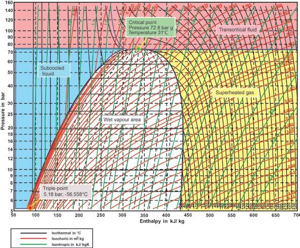
A significant challenge with the application of CO2 as a
                                                                           refrigerant is the higher operating pressures compared to
                                                                           other commercial refrigerants. The chart in figure 5
                                                                           compares the pressure of R744 with R404A and R134a.

                                                                           The saturation curve for R744 does not extend beyond 31°C
                                                                           because this is the critical point - above this condition there
                                                                           is no distinction between liquid and gas. Operation above
                                                                           this pressure is current practice in transcritical systems.

                                                                           Section 3. An introduction to transcritical operation
                                                                           Many R744 systems operate above the critical point some
                                                                           or all of the time. This is not a problem, the system just
                                                                           works differently.

                                                                           •     R744 systems work subcritical when the condensing
                                                                                 temperature is below 31°C
                                                                           •     R744 systems work supercritical when the “gas cooler
                                                                                 exit temperature” is above 31°C and the evaporating
                                                                                 temperature is below 31°C

Figure 5. Pressure-temperature relationship comparison

Figure 6. R744 pressure enthalpy chart showing subcritical and transcritical system

                                                                                                                                             7
CO2 Product Guide 2021 - for Refrigeration Applications
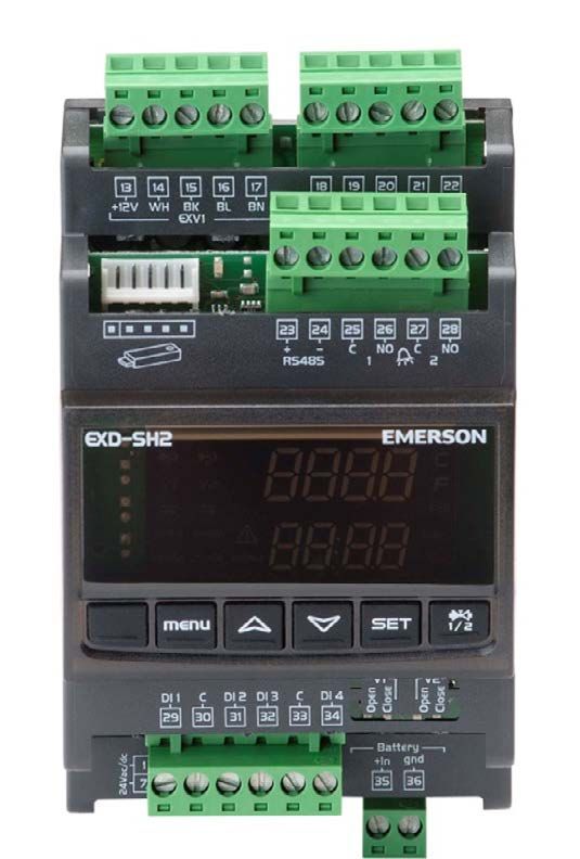
HFC systems work always subcritical because the                                         For example, increasing the high side pressure will increase
    condensing temperature never exceeds the critical                                       the cooling capacity. This is covered in more detail in
    temperature (e.g., 101°C in the case of R134a).                                         chapter 4.

    The pressure enthalpy chart in figure 6 shows an example
    of a simple R744 system operating subcritically at a low                                Section 4. Behaviour in the reference cycle
    ambient temperature and transcritically at a higher ambient
    temperature. The chart shows that the cooling capacity at                               Simple comparisons between R744 and other refrigerants
    the evaporator is significantly less for transcritical operation.                       can be misleading because the low critical temperature of
                                                                                            R744 either leads to differences in system design, such as
    A capacity drop also occurs with HFC systems when the                                   the use of cascade systems, or to supercritical operation.
    ambient temperature increases, but the change is not as                                 So like-for-like comparisons are not easy to make.
    great as it is with R744 when the change is from
    sub- to transcritical.                                                                  The table below provides a simple theoretical comparison
                                                                                            between R744 and common HFC refrigerants and shows
    It is important that appropriate control of the high side                               the performance of ideal cycles.
    (gas cooler) pressure is used to optimise the cooling
    capacity and efficiency when supercritical.

    Table 3. Theoretical comparison between R744 and common HFC refrigerants.

                                                                                                                                              Pressure Vol. cooling
                             Psuc                  Tsuc             Pdis       Tdis_sat       Tdis          ΔH          ΔW          COP
                                                                                                                                                ratio       cap

                          (bar abs)                (°C)         (bar abs)          (°C)       (°C)       (kJ/kg)      (kJ/kg)          (-)        (-)          (kJ/m3)

                                                             Overview refrigerant data related to 4 different system cases

          R744         MT        30.47               -5             97.00          +38*      103.39      135.56        68.53        1.98          3.2           10624
     1
          R744          LT       14.30              -30             30.47              -5     37.30      255.03        44.04        5.79          2.1            9089
          R134a        MT           2.17             -8             10.16          +40        60.67      141.63        43.98        3.22          4.7            1496
     2
          R744          LT       14.30              -30             30.47              -5     37.30      255.03        44.04        5.79          2.1            9089

          R134a        MT           2.17             -8             10.16          +40        60.67      141.63        43.98        3.22          4.7            1496
     3
          R404A         LT          1.81            -33              5.57              -3     16.74      157.28        30.99        5.08          3.1            1428

          R134a        MT           2.17             -8             10.16          +40        60.67      141.63        43.98        3.22          4.7            1496
     4
          R404A         LT          1.81            -33             18.30          +40        68.77         89.29      64.57        1.38         10.1             811

    The four systems are:

                         1                 2                3                  4
                                                                                               Legend for above table
                                                            HFC                                Psuc =               Suction pressure
         Case                         Hybrid                               Centralized
                       R744                               cascade
                                      R744/                                  direct            Tsuc =               Suction temperature, saturated
                      booster                             R404A/
                                      R134a                                expansion
                                                           R134a                               Pdis =               Discharge pressure

         MT to           -5 °C             -8 °C            -8 °C              -8 °C           Tdis_sat =           Discharge temperature, saturated

           tc          +38 °C          +40 °C             +40 °C             +40 °C            Tdis =               Calculated real discharge temperature

         LT to         -30 °C          -30 °C              -33 °C             -33 °C           ΔH =                 Enthalpie-difference through evaporator
                                                                                               ΔW =                 Enthalpie-difference through compressor
           tc            -5 °C             -5 °C            -3 °C            +40 °C
                                                                                               COP =                Coefficient of performance
    Superheat = 6K in all examples                                                             Pressure ratio =     Compression ratio
    Subcooling = 0K in all examples
                                                                                               Vol. cooling cap =   Volumetric Cooling Capacity as ratio
    *gas cooler outlet temperature
                                                                                                                    of evaporator enthalpy difference to the
                                                                                                                    specific volume of suction gas

    Compressor isentropic efficiency:
    For R744 >> 0.75                                                                        Assumptions:
    For R404A >> 0.65                                                                       • No suction or discharge line pressure losses
    For R134a >> 0.6                                                                        • R744 transcritical: optimum discharge pressure 97 bar

8
CO2 Product Guide 2021 - for Refrigeration Applications
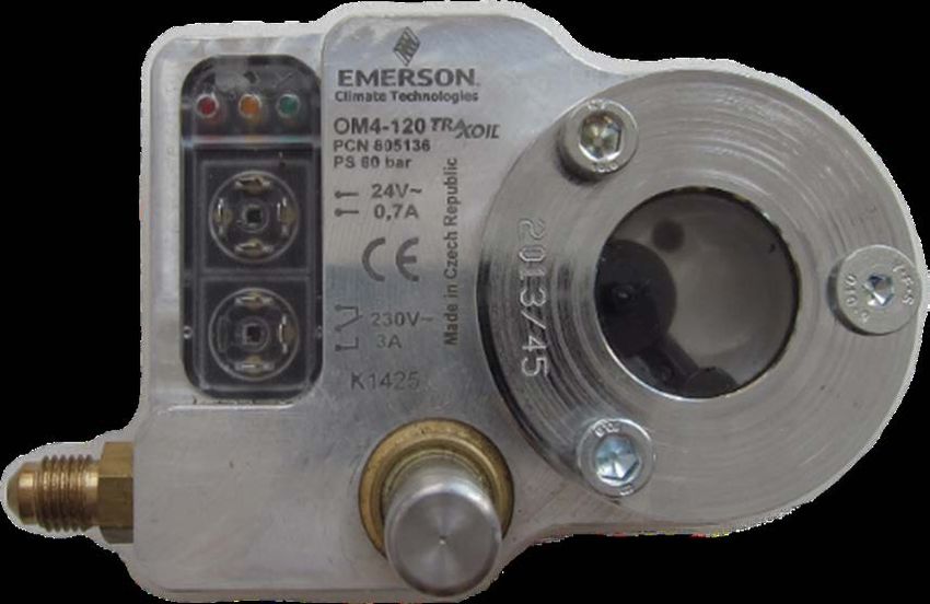
The table highlights the following key points:                                  Table 4. Effects of CO2 at various concentrations in air

•      R744 compares reasonably well with the HFCs when                             ppm of CO2                                Effects
       subcritical and at low condensing temperatures
       (e.g., the LT comparison). But at higher condensing                                370              Concentration in atmosphere
       temperatures (MT example) and when transcritical
                                                                                         5,000             Long-term exposure limit (8 hours)
       (HT example), it does not compare well.
                                                                                        15,000             Short-term exposure limit (10 min)
•      The high suction pressure and high gas density of
       R744 results in very good evaporator performance.                                30,000             Can be “tasted”
       In like-for-like systems the evaporator temperature
       of an R744 system would, in reality, be higher than                                                 Discomfort, breathing, difficulties,headache,
                                                                                        30,000
                                                                                                           dizziness, etc.
       for HFC systems.
                                                                                        100,000            Loss of consciousness, death
•      The index of compression is very high for R744, so the
       discharge temperature is higher than for the HFCs.                               300,000            Quick death
       This can improve heat reclaim potential in retail
       systems, although the requirement for heat in the
       summer when the system is transcritical is limited.                      If a leak of R744 could result in a concentration exceeding
                                                                                the practical limit in an enclosed occupied space such
•      The density of R744 results in very high volumetric                      as a cold room, precautions must be taken to prevent
       capacity. This reduces the required compressor                           asphyxiation. These include the use of permanent leak
       displacement (but not the motor size, which would                        detection which activates an alarm in the event of a leak.
       be similar to that required for HFC refrigerants).
                                                                                High-pressures
•      The required suction pipe cross section area is in
       proportion to the volumetric capacity. For R744                          System components, pipe work, tools and equipment must
       the diameter of the suction line is approximately half                   be rated for these pressures. It should be noted that the
       that required for R404A.                                                 standstill pressure on some systems (e.g., cascade systems)
                                                                                is higher than the maximum rated pressure PS (hence the
•      The compression ratio for R744 is less than for the                      pressure-relief valve setting). The pressure-relief valve will
       HFCs. This can result in higher isentropic efficiency.                   discharge in the event of a fault such as a power failure.

Section 5. R744 hazards                                                         Table 5. R744 standstill and typical system
                                                                                operating pressures
R744 is not flammable, but its high-pressures, toxicity at
high concentration and potential for dry ice formation must
                                                                                 Standstill at 10°C ambient                            44 bar g
be taken into account when applying and handling. This
section explains some of the hazards and provides very
                                                                                 Standstill at 30°C ambient                            71.1 bar g
general guidance on reducing them. More detailed
information relating to the design of systems to
                                                                                 Low temperature evaporator (frozen food)              10 - 15 bar g
minimise the hazards is provided later in this document.
                                                                                 High temperature evaporator (chilled food)            25 - 30 bar g
Asphyxiation
                                                                                 Cascade condenser                                     30 - 35 bar g
R744 is odourless, heavier than air and is an asphyxiant.
The practical limit1 of R744 is lower than HFCs because of
                                                                                 Cascade high-pressure cut out (high side)             36 bar g
its potential for high toxicity (HFCs are non toxic):
                                                                                 Cascade pressure-relief-valve (high side)             40 bar g
Practical limit of R744, 0.1 kg/m3 (56.000 ppm);
Practical limit of R404A, 0.48 kg/m3 (120.000 ppm)
                                                                                 Transcritical high side                               90 bar g

Note – The practical limit is defined in EN378 but may vary
                                                                                 Transcritical high-pressure cut out (high side)       108 to 126 bar g
in regional regulations.
                                                                                 Transcritical pressure-relief valve (high side)       120 to 140 bar g
The table below summarises the effect of CO2 at various
concentrations in air.

1
    EN378 Refrigerating systems and heat pumps – Safety and environmental requirements
    ISO 5149 mechanical refrigerating systems used for cooling and heating - Safety requirements.

                                                                                                                                                           9
CO2 Product Guide 2021 - for Refrigeration Applications
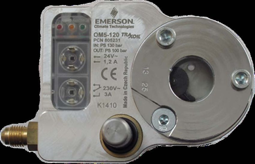
To ensure the pressure does not rise to the relief pressure          liquid temperature to rise more than for other refrigerants.
     in the event of such a fault, these systems can be fitted            Systems should be fitted with pressure-relief protection
     with a small auxiliary cooling system. This typically runs           wherever liquid could be trapped, either during operation or
     on an auxiliary (uninterruptable) power supply and will              service. Methods of providing this protection are covered in
     switch on when the pressure rises above a set point (this is         the section on design of R744 systems.
     lower than maximum allowable suction pressure PS, but
     higher than the normal operating pressure). The auxiliary            Dry ice
     cooling system is sized to remove sufficient heat to keep
     the standstill pressure below safe low side limit when there         Dry ice (solid R744) is formed when R744 pressure and
     is no load on the system (apart from heat absorbed from              temperature is reduced to below the triple point (4.2 bar
     the ambient).                                                        g, -56°C). This will not occur within a properly working
                                                                          refrigeration system, but can occur when:
     Care must be taken when charging R744 systems. The
     maximum operating pressure of some systems (such as                  •   A pressure-relief valve discharges if it is venting
     cascade systems and parts of transcritical systems) is                   vapor R744
     normally below the R744 cylinder pressure. These                     •   Venting R744 during service (component change or
     systems must be charged slowly and carefully to prevent                  replacement, for example)
     pressurerelief valves discharging. Further information is
                                                                          •   Charging a system which is below 4.2 bar g (e.g., an
     given in Chapter 5.
                                                                              evacuated system)

     Trapped liquid
                                                                          Dry ice does not expand when it is formed, but dry ice will
                                                                          become gas as it absorbs heat (e.g., from ambient). If the
     The coefficient of expansion for R744 is significantly higher
     than for other refrigerants. The practical impact of this on         dry ice is trapped within the system, it will absorb heat
     liquid R744 trapped between closed valves is shown in the            from the surroundings and turn into gas. This will result
     graph in figure 7:                                                   in a significant pressure increase.

                                                                          Dry ice can block vent lines, so care must be taken to ensure
                                                                          that this cannot occur:

                                                                          •   Appropriate pressure-relief valves should be used –
                                                                              see the section on system design for more information
                                                                              about these and how safety valves should be applied;
                                                                          •   When R744 is vented from a system during service it
                                                                              should be vented as a liquid, and the pressure in the
                                                                              system monitored. R744 should always be vented
                                                                              outside a building.

                                                                          Freeze burns

                                                                          Contact with solid or liquid R744 will cause freeze burns
                                                                          and should be avoided. Suitable gloves and goggles should
                                                                          always be worn when working with R744.

     Figure 7. Relationship between temperature and pressure of trapped
                                                                          Section 6. Comparison of R744 with
     liquid R744. Source: Danish Technological Institute                  other refrigerants
                                                                          The table below shows a simple comparison of R744 with
                                                                          other types of refrigerant, including those that are currently
     The example shows the effect of a 20K temperature rise on            commonly used and those that are currently evaluated
     liquid that is trapped at an initial temperature of -10°C. The       for future use. It uses a simple “traffic light” system and
     pressure will increase from 44 bar g to approximately 240            employs the common HFCs, such as R404A and R134a
     bar g. This condition could potentially occur in a liquid line       as a baseline.
     of a cascade system, and similar situations can arise in other
     parts of the system and in other R744 systems. As a rule of          This provides a very simple introduction to the options –
     thumb, trapped R744 liquid will increase in pressure by 10           the situation varies globally, especially in the availability of
     bar for every 1K temperature increase.                               refrigerants, components and expertise.

     The pressure of trapped liquid refrigerant always increases,         For retail applications a well designed and installed R407A/F
     but the pressure increase of R744 is much greater than               system generally has better efficiency than R744 systems.
     for other refrigerants. This is exacerbated by the potential
     to trap R744 at low temperatures (LT) and hence for the

10
However, the overall environmental performance of R744 systems is better, primarily due to the low GWP in the event
of leakage.

Table 6. Comparison of R744 with other refrigerants

                                                                       R744               HFOs                    HCs     R717
     Capacity
     Efficiency
     Pressure
     Environmental impact
     Flammability
     Toxicity
     Availability of refrigerant
     Availability of components
     Availability of expertise
     Cost of refrigerant
     Cost of system

                      Refrigerant is similar to HFCs;
                      Aspect of the refrigerant is worse than HFCs;
                      Aspect of the refrigerant is better than HFCs.

HFO: Hydro Fluoro Olefin, e.g., R1234yf
HC: Hydrocarbon, e.g., R290
R717: Ammonia

*
    Reference: Refrigerant choices for commercial refrigeration (TGE124-0910/E) available on climate.emerson.com/en-gb.

                                                                                                                                 11
Section 7. Advantages and disadvantages of R744 as a refrigerant
     R744 has the following advantages and disadvantages as a refrigerant. The list of disadvantages appears less than the
     advantages, but these issues should not be overlooked as they have a significant impact on the safety and reliability of
     R744 systems. More information on the impact of the differences is highlighted below.

     Table 7. Advantages and disadvantages of R744 as a refrigerant

                                Advantages                                                       Disadvantages

      •   High refrigeration capacity due to high volumetric             •   High operating and standstill pressures are more
          cooling capacity (e.g., it is approximately up to 5 times          hazardous and increase the leak potential. Specially
          that of R404A). This has a positive impact on compressor           designed components are required.
          displacement and the sizing of heat exchangers and pipe
          work.                                                          •   Special compressors are required because of the higher
                                                                             refrigeration capacity (different motor / displacement
      •   Lower pressure drops in pipe work and heat                         combination).
          exchangers.
                                                                         •   R744 systems are more complex – either cascade or
      •   For example, the impact of long suction and liquid lines           transcritical. This leads to higher costs in components
          is less.                                                           and installation.

      •   High heat transfer in evaporators and condensers due to the    •   Pipe working on-site potentially includes steel or stainless
          highpressure and density. This will either allow lower             steel, the need for specially licensed welders, and
          temperature differences between the refrigerant and                different jointing techniques due to higher pressure and
          the air; therefore improving efficiency, or allow the use of       different materials.
          smaller evaporators and condensers. Tubing wall thickness
          may need to be increased to handle the higher pressures,       •   The greater complexity also increases the probability of
          so careful design is required to take advantage of the             poor performance and reliability, particularly if
          R744 properties.                                                   commissioning is not done well.

      •   The pressure drop across an expansion valve is greater than    •   For transcritical systems two stage compression is required
          with other refrigerants, so the minimum setting for head           for frozen food applications because of the high discharge
          pressure control can be lower. This improves efficiency.           temperature of R744.

      •   Lower compression ratios leading to higher compressor          •   R744 transcritical systems provide better efficiency
          isentropic efficiency.                                             performance in mild ambient conditions than in warmer
                                                                             climates, where they operate predominantly above the
      •   Non-corrosive with most materials. There are very few              critical point. The implementation of parallel compression
          differences to the materials used in HFC systems.                  or ejector technology increases efficiency levels in warm
                                                                             climates but also increases the complexity and overall cost
      •   Good miscibility with compressor lubricants for oil return.        of these systems. Other technologies are available from
          Polyolester type lubricants can continue to be used                various manufactures to boost efficiency performance in
          as with HFCs.                                                      warm environments.

      •   Low toxicity and nonflammable.                                 •   R744 is not controlled by any regulation such as the
                                                                             European Fluorinated Gas Regulation, so its use is not as
      •   Negligible GWP so that, in the event of a leak, the direct         carefully monitored as HFCs and leak detection is not as
          impact on climate change is very low.                              rigorous. However, the highpressures make the system
                                                                             leak prone, and performance will suffer if the leak
      •   Inexpensive to produce and widely available, although the          rate is high.
          purity of the R744 should be 99.99% for use in a
          refrigeration system with hermetic and semi-hermetic           •   Very sensitive to water contamination and can form
          compressors, i.e., refrigerant grade.                              unusual compounds when there is a leak in a cascade
                                                                             heat exchanger.
      •   High discharge temperatures due to the high index of
          compression. This provides good potential for heat reclaim.
          Note – the discharge temperature is excessively high in
          transcritical systems with a large difference between
          evaporating and heat rejection temperatures.

      •   Stable molecule leading to a low potential for
          decomposition within the refrigeration system.

      •   There is no impending legislation phasing down or phasing
          out R744 so it can be viewed as a long-term refrigerant.

12
ZO & ZOD Copeland™ Scroll compressor range for
CO2- subcritical refrigeration
ZO Copeland Scroll Compressors have been designed for use
in R744 (CO2) low temperature refrigeration systems. These
compressors are suitable for usage in CO2-subcritical cascade and
booster systems.

Increasing environmental concerns about potential direct
emissions from HFC-based refrigeration systems into the
atmosphere have led to the revival of R744 in parts of the
European refrigeration market. Regionally, this trend is reinforced
by legislation and taxation schemes which favor the usage of
refrigerant R744.

In comparison with HFC refrigerants, the specific properties
of R744 require changes in the design of the refrigeration
system. The ZO range of Copeland Scroll compressors has been
particularly designed to exploit the characteristics of the R744
refrigeration system. Efficiency, reliability and liquid handling
advantages of the Copeland scroll technology equally apply.

The optimized design of ZO compressors effectively address the
challenges of R744 systems i.e., high pressure levels, higher mass
flow for a given displacement while securing proper lubrication.

The range consists of 6 models including 2 digital models for 10
                                                                                                                 ZO compressor for low temperature
to 100% continuous cooling capacity modulation.
                                                                                                                          refrigeration

ZO/ZOD compressor range
    Digital ZOD

    ZO

    Cooling capacity (kW)
                            0      2       4        6           8   10                               12            14           16           18            20            22         24

Conditions EN12900 R744: Evaporating -35°C, Condensing -5°C , Suction Superheat 10K, Subcooling 0K

Features and benefits                                               Operating envelope R744
•    Optimized for high efficiency in CO2 subcritical
                                                                                                     10
     cascade and booster systems
•    52 bar standstill pressure on discharge side                                                     5
                                                                                    t mperature °C

     for ZO Scroll                                                                                    0
•    High condensing temperature limit allowing
                                                                                                      -5
     for optimized overall system design
                                                                         Condensing te

•    Compact design minimizing required machine                                                      -10

     room space
                                                                                                     -15
•    Half the weight of equivalent
     semi-hermetic compressors                                                                       -20

•    Optional Sound Shell allowing 10
                                                                                                     -25
     dBA sound attenuation                                                                                 -55      -50      -45       -40        -35       -30         -25   -20

•    High bearing reliability and lubrication of all critical                                                                 Evaporating te
                                                                                                                                          t mperature °C
                                                                                                                    0°C Suction gas return              20K superheat
     parts under all conditions including liquid slugging
•    Availability of a digital model offering simple,
     stepless 10 to 100% capacity modulation

                                                                                                                                                                                         13
ZO & ZOD Copeland™ scroll compressor range
     for CO2- subcritical refrigeration

     Technical overview

                                                                                                                         Maximum        Locked
                                                                                                             Motor
                                                                                   Length /                              operating       rotor     Sound
                                          Stub     Stub     Oil                                  Net        version /
                   Nominal Displacement                                             width /                               current       current   pressure
        Model                           suction discharge quantity                              weight        code
                    (hp)      (m /h)
                                 3
                                                                                    height                                  (A)           (A)      @1 m -
                                         (inch)   (inch)     (l)                                 (kg)
                                                                                    (mm)                                                          dB(A)***
                                                                                                             3 Ph**           3 Ph**    3 Ph**

       ZO21K5E        1.5           2.6           1 1/4           1     1.0       228/228/388    22.2         TFD              3.6           27     60
       ZO34K3E         2            4.1           1 1/4           1     1.4       242/242/381    30           TFD              5.5           26     54
       ZO45K3E        2.5           5.4           1 1/4           1     1.4       242/242/403    31           TFD              6.2           35     56
       ZO58K3E        3.5           6.9           1 1/4           1     1.4       242/242/417    32.5         TFD               8            48     56
       ZO88KCE         5            10.1          1 1/4           1     1.9       245/249/440    40.3         TFD              11.8          64     60
      ZO104KCE         6            11.7          1 1/4           1     1.9       242/242/461    40           TFD              15            74     61
                                                                         Digital models
      ZOD34K3E         2            4.07          1 1/4           1     1.4       242/242/377    30           TFD              5.5           26     62
      ZOD104KCE        6            11.7          1 1/4           1     1.9       241/246/484    41           TFD              15            75     67

     Capacity data
                                                          Cooling capacity (kW)                                       Power input (kW)
         R744         Condensing
                     temperature                     Evaporating temperature °C                                Evaporating temperature (°C)
                         (°C)
         Model                             -45             -40           -35           -30            -45               -40            -35         -30

       ZO21K5E                             3.2              4.1          5.1           6.2            1.2               1.2            1.2         1.1
       ZO34K3E                             4.8              6.2          7.8           9.7            1.8               1.8            1.8         1.7
       ZO45K3E                             7.0              8.8         10.9           13.3           2.3               2.3            2.3         2.2
                            -10°C
       ZO58K3E                             8.9             11.2         13.9           17.0           3.0               3.0            2.9         2.8
       ZO88KCE                             13.3            17.0         21.0           25.4           4.5               4.5            4.4         4.2
       ZO104KCE                            15.9            19.7         24.1           29.2           4.9               5.0            5.1         5.2
                                                                         Digital models
       ZOD34K3E                            5.1              6.4          7.9           9.7            1.8               1.8            1.8         1.7
                           -10°C
      ZOD104KCE                            15.6            19.1         23.2           27.9           5.0               5.0            5.1         5.3

     Note: 10 K Superheat

14
Copeland™ semi-hermetic compressor with
compressor electronics technology
for R744-transcritical applications
Stream series of 4 cylinder CO2 compressors is the ideal
solution for R744 medium temperature cascade and
booster systems. It is characterized by a design pressure
of 135 bar. Refrigerant flow and heat transfer have
been optimized for best performance. All compressors
are equipped with Copeland compressor electronics
technology and offer the possibility to diagnose system-
related problems faster or even before they occur.

                                                                                                                   Copeland Stream Compressors for R744

Stream compressor range

   R744

    Cooling Capacity (kw)
                             0       5      10     15      20      25      30              35                        40         45           50        55       60       65          70    75

Conditions: EN12900 R744: Evaporating -10°C, Gas cooler exit: 35°C/ 90 bar, Superheat: 10K

Features and benefits
Stream provides for flexibility in pack design and operation:
• Compact dimensions
• Integrated low pressure relief valve
• Discharge Temperature Protection
• Service valve 360° rotation for ease of piping design
• 2 sight glasses for mounting of oil management
    control and visual inspection                                           Operating envelope R744
• One oil port for oil equalization in parallel system
• Oil splasher system ensuring lubrication at constant                          p2 abs (bar)

    and variable speed                                                                                       120

                                                                                                             110
                                                                                  Discharge pressure (bar)

Designed for durability and performance in                                                                   100

R744 applications:                                                                                           90

• Low sound, low vibration and large discharge                                                               80

    chamber to eliminate pulsation                                                                           70

• High design pressures of 135 bar (high side)                                                               60

    and 90 bar (low side)                                                                                    50

• Burst pressures in excess of safety factor 3                                                               40

• Cylinder head and discharge plenum design                                                                        -25    -20        -15      -10      -5   0        5     10        15   20
                                                                                                                                            Evaporating te
                                                                                                                                                        t mperature (°C)
    minimizing heat transfer to suction side                                                                                               10K superh
                                                                                                                                                   r eat             20K superh
                                                                                                                                                                             r eat
• Stepless capacity modulation via inverter
    from 25 to 70Hz
• Copeland compressor electronics technology
• Individual compressor power consumption monitoring

                                                                                                                                                                                                15
Technical overview

                                                                                                                                         Maximum             Locked
                                                                                                                             Motor
                                                                                                        Length /                         operating            rotor       Sound
                                                                                       Oil                          Net     version /
                     Nominal               Displacement        Capacity                                  width /                          current            current     pressure
         Model                                                                COP    quantity                      weight     code
                      (hp)                    (m3/h)             (kw)                                    height                             (A)                (A)        @1 m -
                                                                                        (l)                         (kg)
                                                                                                         (mm)                                                            dB(A)***
                                                                                                                             3 Ph**        3 Ph**            3 Ph**

       4MTL-05X               5.0               4.6               9.3          1.6         1.5     630/425/410     123.0      EWL              13.3           80.5         76.0
       4MTL-07X                   7.0           6.2             12.5           1.6         1.5     630/425/410     124.0      EWL              17.5           81.2         76.0
       4MTL-09X                   9.0           7.4             15.3           1.6         1.5     630/425/410     123.0      EWL              21.0           93.5         76.0
       4MTL-12X             12.0                9.5             19.2           1.7         1.8     697/444/423     170.0     AWM               26.5          145.0         67.4
       4MTL-15X             15.0                12.5            25.2           1.8         1.8     697/445/422     170.0     AWM               34.8          156.0         71.3
       4MTL-30X             30.0                18.0            37.0           1.8         1.8     697/445/422     175.0     AWM               50.0          221.0         75.1
       4MTL-35X                   35            22.7            49.0          1.79         2.5     842/ 468/ 467   257.9     AWM               67.1           304          85.0
       4MTL-40X                   40            26.6            56.0          1.84         2.5     842/ 468/ 467   264.0     AWM               72.6           306          85.0
       4MTL-50X                   50            32.0            70.0          1.81         2.5     842/ 468/ 467   269.4     AWM               90.3           393          85.0
     ** 3 Ph: 380-420V/ 50Hz
     *** @ 1m: sound pressure level at 1m distance from the compressor, free field condition

     Capacity data
                                                                                     Cooling capacity (kW)                                Power input (kW)
                                                                                 Evaporating temperature °C                         Evaporating temperature °C
                                       Temperature     Pressure
            Model                                                       -20          -15         -10         -5      0      -20         -15           -10           -5       0
                                          (°C)           (bar)
                                                                          Equivalent evaporation pressure (bar)               Equivalent evaporation pressure (bar)
                                                                        19.7         22.9        26.5       30.5   34.9     19.7        22.9          26.5       30.5       34.9
                                           10             45            11.0         13.5        16.4       19.8            3.1         3.0           2.7         2.4
                     Condensing

                                           15             50            9.9          12.3        14.9       17.9   21.5     3.4         3.4           3.2         3.0       2.6
                                           20             57            8.8          10.9        13.3       16.1   19.3     3.8         3.8           3.7         3.5       3.2
                                           25             64            7.6          9.5         11.6       14.1   16.9     4.1         4.2           4.1         4.0       3.8
       4MTL-05X
                                           30             75            6.0          7.5         9.3        11.2   13.5     4.4         4.5           4.6         4.6       4.4
                                           35             90                         7.1         8.8        10.8   13.0                 5.3           5.5         5.6       5.6
                     Cool gas

                                           40            100                                      7.6        9.3   11.3                               5.9         6.1       6.2
                                           40            110                                                 9.7   11.8                                           6.5       6.7
                                           10             45            15.1         18.4        22.2       26.5            3.9         3.7           3.4         3.0
                     Condensing

                                           15             50            13.7         16.7        20.2       24.1   28.6     4.4         4.3           4.1         3.7       3.3
                                           20             57            12.2         14.9        18.1       21.6   25.7     4.8         4.8           4.7         4.5       4.1
                                           25             64            10.5         13.0        15.7       18.8   22.4     5.3         5.4           5.3         5.2       4.9
       4MTL-07X
                                           30             75            8.3          10.3        12.5       15.0   17.9     5.7         5.9           6.0         5.9       5.7
                                           35             90                         9.7         11.9       14.3   17.2                 6.9           7.2         7.3       7.4
                     Cool gas

                                           40            100                                     10.2       12.4   14.9                               7.7         8.0       8.2
                                           40            110                                                12.8   15.4                                           8.6       8.9
                                           10             45            18.4         22.4        27.0       32.2            4.7         4.5           4.2         3.7
                     Condensing

                                           15             50            16.6         20.3        24.5       29.4   34.9     5.3         5.2           4.9         4.5        4.0
                                           20             57            14.8         18.2        22.0       26.3   31.3     5.8         5.8           5.7         5.4        5.0
                                           25             64            12.8         15.8        19.2       23.0   27.4     6.4         6.5           6.5         6.3        6.0
       4MTL-09X
                                           30             75            10.1         12.6        15.3       18.4   21.9     6.9         7.1           7.2         7.2        7.0
                                           35             90                         11.9        14.6       17.7   21.1                 8.4           8.7         8.9        9.0
                     Cool gas

                                           40            100                                     12.7       15.3   18.4                               9.4         9.8       10.0
                                           40            110                                                15.9   19.0                                          10.6       10.9
                                           10             45            24.1         29.1        35.0       41.7             6.1         5.9           5.5        4.9
                     Condensing

                                           15             50            21.8         26.4        31.9       38.1   45.0      6.8         6.8           6.5        6.0        5.3
                                           20             57            19.5         23.7        28.6       34.3   40.6      7.6         7.6           7.4        7.0        6.5
                                           25             64            16.9         20.6        25.0       30.0   35.6      8.3         8.4           8.4        8.2        7.7
       4MTL-12X
                                           30             75            13.5         16.4        20.0       24.1   28.6      9.0         9.3           9.4        9.3        9.0
                                           35             90            12.8         15.7        19.3       23.3   27.9     10.2        10.9          11.3       11.6       11.6
                     Cool gas

                                           40            100                         13.6        16.8       20.4   24.4                 11.5          12.2       12.6       12.8
                                           40            110                                     17.4       21.2   25.5                               12.8       13.5       13.9

     Suction superheat 10K / Subcooling 0K

16
Capacity data
                                                               Cooling capacity (kW)                         Power input (kW)
                                                             Evaporating temperature °C                  Evaporating temperature °C
                             Temperature   Pressure
      Model                                           -20      -15      -10       -5        0     -20      -15      -10       -5        0
                                (°C)         (bar)
                                                        Equivalent evaporation pressure (bar)       Equivalent evaporation pressure (bar)

                                                      19.7    22.9      26.5     30.5      34.9   19.7    22.9      26.5     30.5      34.9

                                 10          45       31.2     37.9     45.6     54.4             7.9      7.6      7.1       6.3

                                 15          50       28.3     34.5     41.6     49.7      58.7   8.8      8.7      8.4       7.8      6.9
                Condensing

                                 20          57       25.3     30.9     37.4     44.8      53.0   9.7      9.7      9.6       9.2      8.6

                                 25          64       22.0     26.9     32.7     39.3      46.6   10.5     10.8     10.8     10.7      10.2
  4MTL-15X
                                 30          75       17.5     21.5     26.2     31.6      37.5   11.4     11.8     12.0     12.1      11.8
                                 35          90       16.5     20.5     25.2     30.5      36.5   13.1     13.8     14.4     14.8      15.0
                Cool gas

                                 40          100               17.7     21.8     26.6      31.8            14.8     15.5     16.1      16.4

                                 40          110                        22.5     27.5      33.1                     16.6     17.3      17.9
                                 10          45       45.6     54.9     65.9     78.3             11.4     11.0     10.4      9.3

                                 15          50       41.5     50.2     60.3     71.7      84.4   12.6     12.5     12.1     11.4      10.2
                Condensing

                                 20          57       37.2     45.1     54.3     64.7      76.3   13.9     14.0     13.9     13.4      12.5

                                 25          64       32.4     39.4     47.6     56.9      67.2   15.2     15.5     15.6     15.4      14.8
  4MTL-30X
                                 30          75       25.9     31.6     38.3     45.8      54.2   16.4     16.9     17.3     17.4      17.1
                                 35          90       24.7     30.3     37.0     44.6      53.1   18.8     19.8     20.6     21.2      21.5
                Cool gas

                                 40          100               26.3     32.2     39.0      46.5            21.2     22.2     23.0      23.6

                                 40          110                        33.4     40.5      48.5                     23.8     24.8      25.6
                                 10          45       57.9     69.9     84.2     100.5            14.3     13.7     12.6     11.2

                                 15          50       52.6     63.7     76.8     91.9     109.0   15.9     15.6     14.8     13.6      12.0
                Condensing

                                 20          57       47.1     57.1     69.1     82.8      98.2   17.6     17.6     17.1     16.2      14.9

                                 25          64       41.1     49.9     60.5     72.6      86.2   19.3     19.6     19.4     18.8      17.8
  4MTL-35X
                                 30          75       32.8     40.0     48.5     58.4      69.4   20.9     21.5     21.7     21.5      20.8
                                 35          90       31.5     38.4     46.9     56.7      67.7   23.6     25.1     26.1     26.7      26.9
                Cool gas

                                 40          100               33.5     40.9     49.5      59.3            26.5     28.0     29.1      29.7

                                 40          110                        42.5     51.6      61.9                     29.5     31.1      32.1
                                 10          45       69.0     83.1     99.7     118.5            16.5     15.9     14.7     13.0

                                 15          50       62.8     75.8     91.1     108.5    128.0   18.5     18.2     17.4     16.1      14.1
                Condensing

                                 20          57       56.4     68.1     81.9     97.9     115.5   20.4     20.4     20.0     19.1      17.6

                                 25          64       49.3     59.6     71.8     85.9     101.5   22.4     22.7     22.6     22.1      21.1
  4MTL-40X
                                 30          75       39.5     47.8     57.7     69.1      81.9   24.3     25.0     25.3     25.2      24.6
                                 35          90       38.1     46.2     55.9     67.2      79.9   28.2     29.4     30.4     31.1      31.4
                Cool gas

                                 40          100               40.3     48.8     58.8      70.0            31.8     33.0     34.1      34.8

                                 40          110                        50.8     61.2      73.1                     35.6     36.9      37.9
                                 10          45       82.8     99.7    119.5     142.0            20.2     19.6     18.4     16.7

                                 15          50       75.6     91.1    109.5     130.5    153.5   22.6     22.3     21.5     20.0      18.0
                Condensing

                                 20          57       67.9     82.0     98.6     117.5    139.0   24.9     25.1     24.6     23.5      21.9

                                 25          64       59.5     71.9     86.5     103.5    122.0   27.3     27.8     27.8     27.2      25.9
  4MTL-50X
                                 30          75       47.7     57.8     69.7     83.4      98.6   29.6     30.6     31.1     30.9      30.1
                                 35          90       46.2     56.0     67.8     81.4      96.7   33.9     35.9     37.4     38.3      38.6
                Cool gas

                                 40          100               49.0     59.3     71.3      84.8            38.2     40.3     41.8      42.6

                                 40          110                        61.9     74.5      88.8                     42.6     44.7      46.2

Suction Superheat 10K / Subcooling 0K

                                                                                                                                              17
Copeland™ semi-hermetic compressor with compressor
     electronics technology for R744- subcritical applications
     requiring high standstill pressures (90 bar)
     Stream series of 4 cylinder CO2 compressors is the ideal
     solution for R744 low temperature cascade and booster
     systems requiring high standstill pressure of up to 90 bar
     Suction. The use of transcritical compressors in medium /
     transcritical side as well as on the low temperature / subcritical
     side ensures that in case of power outage, the refrigeration
     system features full resilience and no operation disruption.

     Stream is characterized by a design pressure of 135 bar.
     Refrigerant flow and heat transfer have been optimized
     for best performance. All compressors are equipped with
     Copeland compressor electronics technology and offer the
     possibility to diagnose system-related problems faster or even
     before they occur.                                                                                                  Copeland Stream Compressors for R744

     Stream compressor range

        R744

        Cooling capacity (kw)
                                0                          5                                                 10                               15                                  20

     Conditions: EN12900 R744: Evaporating -35C, Condensing -5C, Superheat 10K, Subcooling OK

     Features and benefits                                                    Operating envelope R744
     Stream provides for flexibility in pack design and operation:
     • Compressor max. pressures (suction/discharge):                                                        30

         90 bar / 135 bar
                                                                                                             20
     • Compact dimensions
                                                                                            t mperature °C

     • Integrated low pressure relief valve
                                                                                                             10
     • Discharge Temperature Protection
     • Service valve 360° rotation for ease of piping design                                                  0
                                                                                 Condensing te

     • 2 sight glasses for mounting of oil management
         control and visual inspection                                                                       -10
     • One oil port for oil equalization in parallel system
     • Oil splasher system ensuring lubrication at constant                                                  -20

         and variable speed
                                                                                                             -30
                                                                                                                   -55   -50   -45     -40   -35   -30    -25      -20      -15    -10
     Designed for durability and performance in R744                                                                                 Evaporating te
                                                                                                                                                 t mperature °C

     applications:                                                                                                         10K superh
                                                                                                                                   r eat           0°C Suction gas re
                                                                                                                                                                   r turn
     • Low sound, low vibration and large discharge chamber
         to eliminate pulsation
     • Optimized motor selection for low temperature
         running conditions
     • Burst pressures in excess of safety factor 3
     • Cylinder head and discharge plenum design
         minimizing heat transfer to suction side
     • Stepless capacity modulation via inverter from
         25 to 70Hz
     • Copeland compressor electronics technology for
         advanced protection, diagnostics, communication
     • Individual compressor power consumption monitoring

18
Technical overview

                                                                                                                      Maximum       Locked
                                                                                                        Motor
                                                                               Length /                               operating      rotor        Sound
                                                                Oil                           Net      version/
              Nominal Displacement        Capacity                              width /                                current      current      pressure
    R744                                                COP   quantity                       weight     code
               (hp)      (m3/h)            (kW)                                 height                                   (A)          (A)         @1 m -
                                                                 (l)                          (kg)
                                                                                (mm)                                                             dB(A)***
                                                                                                       3 Ph**           3 Ph**       3 Ph**

 4MSL-03X        3.0           4.6            7.2       3.2      1.5          630/425/410    120.0          EWL          7.0          49.6         54.0
 4MSL-04X        4.0           6.2            9.9       3.6      1.5          630/425/410    120.0          EWL          8.8          49.6         56.0
 4MSL-06X        5.0           7.4            12.4      3.7      1.5          630/425/410    120.0          EWL          10.5         61.9         56.0
 4MSL-08X       10.0           9.5            15.9      3.6      1.8          697/444/423    170.0      AWM              13.9         87.4         76.0
 4MSL-12X       12.0           12.5           21.0      3.7      1.8          697/445/422    170.0      AWM              18.7        145.0         76.0
 4MSL-15X       15.0           17.9           31.0      3.8      1.8          697/445/422    170.0      AWM              25.7        156.0         76.0

** 3 Ph: 380-420V/ 50Hz
*** @ 1m: sound pressure level at 1m distance from the compressor, free field condition

Capacity data
                                                      Cooling capacity (kW)                                            Power input (kW)
     R744          Condensing
                  temperature                    Evaporating temperature (°C)                                     Evaporating temperature (°C)
                      (°C)
    Model                               -45             -40            -35            -30             -45              -40           -35          -30

  4MSL-03X                              4.8             6.3            8.2            10.5            1.9              2.0           2.0          1.9
  4MSL-04X                              6.7             8.8            11.3           14.2            2.5              2.6           2.5          2.4
  4MSL-06X                              8.0            10.5            13.5           16.9            2.9              3.0           2.9          2.7
                       -10°C
  4MSL-08X                             10.3            13.5            17.2           21.5            3.8              4.0           3.9          3.7
  4MSL-12X                             13.8            17.9            22.7           28.4            4.9              5.0           5.0          4.8
  4MSL-15X                             20.3            26.3            33.4           41.5            7.0              7.2           7.2          7.0
Conditions: Suction Gas Return 20°C / Subcooling 0K
*Conditions: Suction Superheat 10K, Subcooling 0K

                                                                                                                                                            19
Copeland™ Outdoor Refrigeration Units for
     R744-Transcritical Applications
     With this range of outdoor refrigeration units, Emerson offers a solution which
     responds to the increasing demand for future proof refrigeration technology.

     These models are designed for operation with the natural refrigerant CO2 which
     has a very low global warming potential (GWP) of only 1.

     The range features the latest technology like Stream series compressors which
     are characterized by their silent and reliable operation. The integrated frequency
     inverter controls the compressor speed exactly to the capacity demand of the
     application. EC-fans remove the heat from the gas cooler in the most efficient
     and silent way.

     The state of the art electronic contoller allows for precise adjustment and control
     of all relevant parameters and comprises numerous electronic protection
     functions for highly reliable operation.                                                                                                 Copeland outdoor refrigeration unit
                                                                                                                                               for R744-transcritical applications
     The refrigeration units are future-proof choice for various target applications:
     •      Convenience stores
                               • Cold rooms
     •      Forecourt sites				• Fast food stores, bars and restaurants

     R744 refrigeration unit line-up
         OME-4MTL-05X
         OME-4MTL-07X
         OME-4MTL-09X
         OME-4MTL-12X*
         Capacity (kW)
                                0                                                  5                                            10                          15                        20

     * Preliminary Data

     Technical overview
                                                 Cooling capacity

                                                                                                                                                                                       Sound pressure
                                                                                       diameter (inch)

                                                                                                         diameter (inch)

                                                                                                                                                                                       @10m - d(BA)*
                                @ 50 Hz (m3/h)
                                Displacement

                                                  @ 50 Hz (kW)

                                                                                         Suction line

                                                                                                                                               Net weight
                                                                    capacity (l)

                                                                                                            Liquid line
                                                                     Receiver

                                                                                                                                                                            Nominal
                                                                                                                               Width/depth/
                                                                                                                                                  (kg)

                Model                                                                                                                                       Power supply    current
                                                                                                                               height (mm)
                                                                                                                                                                              (A)

      OME-4MTL-05X (HP**)           4.6           8.69                                    3/4               5/8             1574/920/1135       450                           19      42 - 44

      OME-4MTL-07X (HP**)           6.2          11.80                                    3/4               5/8             1574/920/1135       450                           22      42 - 44
                                                                                                                                                             3/N/PE~50Hz
                                                                    24.9
                                                                                                                                                            400/230V TN-S
      OME-4MTL-09X (HP**)           7.4          14.25                                    7/8               5/8             1574/920/1135       462                           27      42 - 44

      OME-4MTL-12X                  9.5          17.00                                    7/8               5/8             1574/920/1135       473                           33      45 - 47
     Conditions EN13215: R744, evaporating temperature -10°C, ambient temperature 32°C, suction superheat 10 K
     * @ 10m: sound pressure level at 10m distance from the compressor, free field condition
     **90 bar liquid line.
     Preliminary cata
     For detailed capacity data please refer to Emerson’s Select software

     Features and benefits
     • Future-proof solution with natural GWP 1 refrigerant, not                                                           •     Modbus communication and monitoring functionality
            impacted by F-Gas legislation                                                                                  •     LCD display to show the operation status
     •      Low carbon footprint                                                                                           •     OilWatch maintains correct system oil level
     •      Silent operation due to special attenuation on panels and                                                      •     Controller prepared for heat recovery
            sound optimized EC fans                                                                                        •     Easy access for time saving service
     •      High energy efficiency through inverter controlled                                                             •     Built and tested in advanced industrial processes
            compressor and EC fans                                                                                         •     Individual compressor power consumption monitoring
     •      Space saving design
     •      Time saving comissioning by pre-set parameters
     •      High reliability with electronic protection against incorrect                                                  Design pressure:
            voltage, phase, current and discharge temperature                                                              • 90 bar in receiver and liquid line
     •      State of the art controller for precise system control                                                         • 120 bar on high-pressure side
20
Emerson CO2 valve application possibilities
Hypothetical layout of a large booster transcritical and subcritical CO2 system to demonstrate application of Emerson
CO2 valve CV and CX2 series as well EX series valves.

Guideline table - applicability
                                     CV4-7                       EX4         EX5-7          EX8                              CX2
                                                                                                        Recommended
             Duty                  PS: 130 bar     Position   PS: 90 bar   PS: 60 bar    PS: 45 bar                       PS: 90 bar
                                                                                                        Emerson driver
                                   PT: 186 bar                PT: 99 bar   PT: 66 bar   PT: 49.5 bar                     PT: 129 bar

  High pressure gas valve              Yes           (A)          No           No            No             EXD-U02          No

  Bypass valve                         Yes           (B)          No           No            No             EXD-U02          No

  Heat reclaim valve                   Yes           (C)          No           No            No             EXD-U02          No

  Expansion valve                      Yes           (D)         Yes          Yes            Yes           EXD-SH1/2         Yes

                                                                                                            EXD-U02
  Suction pressure regulation          Yes            (E)        Yes          Yes            Yes                             No
                                                                                                           EXD-SH1/2
Note: PS = Maximum allowable pressure, PT = Factory pressure test / Standstill pressure
      (System manufacturer can apply PT pressure to the assembly of valve and piping for strength and leakage test).

                                                                                                                                       21
Electronic expansion valves series CX2
     Pulse width modulated expansion valve with exchangeable
     orifices for high-pressure CO2 applications (display cases).

     Features and benefits
     •    Pulse width modulated
     •    Shut-off function eliminates the necessity of a separate
          solenoid valve
     •    Dampened plunger reduces noise effects of water hammer
     •    One valve body can be combined with 6 orifices to make
          7 capacity ranges up to 28.2 kW
     •    Long lifetime, high reliability
     •    PS: 90bar                                                                                                              CX2 with orifice
     •    MOPD: 65 bar

     Selection table
                                                                                 Valve

               Type                  Part No.           Description               Type               Part no.      Description      Nominal capacity R477 (kW)

                                                                                                                                               28.2
                                                                                 EXO-004              801089         Orifice 4                 17.9

                                                                                 EXO-003              801088         Orifice 3                 11.8
                                                           Valve:
              CX2-I00                801 095                                     EXO-002              801087         Orifice 2                 7.0
                                                       3/8” x1/2" ODF
                                                                                 EXO-001              801086         Orifice 1                 5.2
                                                                                 EXO-000              801085         Orifice 0                 2.6
                                                                                 EXO-00X              801084         Orifice X                 1.5
     Note 1: Nominal capacity at -10°C evaporating temperature, +10°C liquid temperature (45 bar) and 1K subcooling.
             For other operating conditions the selection tool “Controls Navigator” can be downloaded from climate.emerson.com/en-gb.

                                                                                 Coil
                                                                                                                     Ambient
             Type coils              Part No.          Supply voltage         Power input           Description                              Picture
                                                                                                                   temperature
                                                                                                        IP 65
                                                        24 VAC ±10%                                   properly
            ESC-24VAC                 801033                                                        installed on
                                                         50(60) Hz
                                                                                                     enclosing
                                                                                                     tube with
                                                                                  17VA                              -40...+60°C
                                                                                                     plug/cable
                                                                                                      assembly
                                                       230 VAC ±10%                                    acc. EN
            ESC-230VAC              801031/M*
                                                         50(60) Hz                                   60529 test
                                                                                                     conditions
     Note: Orifice should be selected at max. 80% of Qn to allow covering the load fluctuation.

     Cable assembly for ESC coils
                        Type                      Part No.         Description           Cable length       Temperature range                Picture

                      ASC-N15                   804570/M*                                   1.5 m
                                                                                                                 -50…+80°C
                                                                Connector Cable
                      ASC-N30                   804571/M*                                   3.0 m           (valid for stationary
                                                                   Assembly
                                                                                                                     use)
                      ASC-N60                   804572/M*                                   6.0 m
                    Plug PG9                      801012        Plug acc. EN175301 with cable gland
                    Plug PG11                     801013        Plug acc. EN175301 with cable gland
                      ESC-K01                     801034        Screw cap (incl. 2x O-ring & fixing retainer)
     Note: *) Multipack = 20 pcs.

22
High-pressure electrical controls valves series CV4-7
Emerson CV4-7 are stepper motor driven valves for precise
control of refrigerant mass flow in CO2 systems and can be
applied as (see next page):
• High pressure gas valve (A)
• Bypass valve (B)
• Heat reclaim valve (C)
• Expansion valves (D)
• Suction pressure regulating valve (E)

Features and benefits
•    Maintenance free
                                                                                                                         CV5-HPV
•    Multifunction
•    Fully hermetic design with ODF connections
•    Stepper motor driven
•    Short opening and closing time
•    Very fast full stroke time                                               •     Optimal solution applied to offer the highest reliability
•    High resolution and excellent repeatability                                    and lifespan, accordingly to the high differential pressures
•    Positive shut-off function to eliminate the use of an                          in the CO2 systems
     additional solenoid valve                                                •     Ceramic slide and port for precise flow and minimal wear
•    Linear flow capacity                                                     •     Balanced force design
•    Extremely wide capacity range (10…100%)                                  •     Corrosion resistant stainless-steel body and connections

Selection table
       Type            Part No.       Kv (m3/hr)         Capacity range      Inlet connection            Outlet connection          Electric connector

     CV4-HPV            802056           0.21                                     3/8” ODF               5/8” (16 mm) ODF

     CV5-HPV            802057           0.68                                5/8” (16 mm) ODF            7/8” (22 mm) ODF
                                                            10…100%                                                                      M12 Plug
     CV6-HPV            802058           1.57                                7/8” (22 mm) ODF               1-1/8” ODF

     CV7-HPV                             5.58                                     1-1/8” ODF                1-1/8” ODF
Note1: The valves are delivered without cable/connector assembly (order separately).

Cable and connector assembly
                                                         Temperature       Connector type       Connector type to driver
       Type            Part No.      Length (m)                                                                                         Illustration
                                                            Range             to valve            board or controller

     EXV-M15            804663           1.5
     EXV-M30            804664           3.0               -50…+80°C              M12                     Loose wires
     EXV-M60            804665           6.0

Emerson driver / controller to drive CV valves

               Type                             Function                      Analogue signal input                                Remark

                                                                          0-10VDC or 4-20 mA signal from                 Refer to technical bulletin of
      EXD-U02 for one valve                      Slave
                                                                                master controller                                  EXD-U02

      EXD-SH1 for one valve
                                            Superheat or                      Pressure transmitter and                   Refer to technical bulletin of
                                        temperature controller                  temperature sensor                                EXD-SH1/2
      EXD-SH2 for two valves

    Third party driver/controller                                              See page 4 for requirements

                                                                                                                                                          23
Technical data
      Marking
                                          not required (Out of scope of PED)           Protection accordance to              IP67 with EXV-Mxx
                                                                                       IEC 529, DIN 40050                    plug and cable assembly
                                   UL     CV4/5/6 (No.MP604)
      Compatibility                       CO2 and POE lubricants
                                                                                       Vibration                             4g (0…1000 Hz, 1 octave /min.)
                                          70 bar
      MOPD
                                          (In conjunction with EXD-U02 driver)
                                                                                                                             20g at 11 ms
                                                                                       Shock (CV4-6)
      Max. allowable pressure PS          130 bar                                                                            80g at 1 ms

      Factory test pressure PT            186 bar
                                                                                       External leakage                      6.4*10-6 mbar*liter/sec.
      Temperatures
                              Ambient     -40…+65°C
                               Storage    -40…+70°C                                    Humidity                              100% R.H.
                              Medium      -50…+100°C

     Electrical data
                                          Bi-polar, phase current by chopper            Step mode                            2 phase full step
      Stepper motor type
                                          control (constant current)
                                                                                        Stepping rate                        500 Hz
      Electrical connection               4 pins terminal for M12 plug
      Driver supply voltage                                                                                                  CV4-6: 750 full steps
                                          18…36VDC                                      Total number of steps
      to the valve                                                                                                           CV7: 6400 full steps.
      Operating (moving)                  CV4: 625 mA                                                                        CV4: 14 Ohm ±10%
                                                                                        Winding resistance per phase
      current peak                        CV5-7: 800 mA                                                                      CV5-7: 10 Ohm ±10%
                                          CV4: 100 mA                                                                        CV4-6: 1.5 seconds
      Holding current peak                                                              Full travel time
                                          CV5-7: 300 mA                                                                      CV7: 12.8 seconds
                                          CV4: 30 mH ± 25%                                                                   Mechanical stop at
      Phase inductance                                                                  Reference position
                                          CV5/6/7: 20 mH ± 25%                                                               fully close position

     Dimensions (mm)
                 Type                        CV4-HPV                           CV5-HPV                          CV6-HPV                             CV7-HPV

                Part No.                      802056                           802057                            802058
           Ø A x Ø F (ODF)               3/8” x 5/8” (16 mm)       5/8” (16 mm) x 7/8” (22 mm)             7/8” (22 mm) x 1-1/8”                 1-1/8” x 1-1/8”
                B (mm)                              8                            11                                 16                                 20
                C (mm)                           45                              55                                 65                                 78
                D (mm)                           55                              65                                 75                                 83
                E (mm)                           11                              16                                 19                                 20
                H1 (mm)                         113                              125                               125                                205
                H2 (mm)                          26                              26                                 26                                 42
                H2 (mm)                          26                              26                                 26                                 42

                                                                                                                         F

24
Electrical control valves series EX4-8
Features and benefits
                                                                                                  EX4
•    Multifunction as expansion valve, hot gas bypass,
     suction gas throttling, head pressure, liquid level actuator etc.                                                    EX5
•    Fully hermetic design (no thread joints between
     valve body and motor compartment)
•    Applicable to all common refrigerants (HCFC, HFC)
     and for subcritical CO2 applications
•    Stepper motor driven
•    Short opening and closing time                                                                EX6
•    High resolution and excellent repeatability
•    Positive shut-off function to eliminate the need for additional
     solenoid valve                                                                                                           EX7
•    Bi-flow versions for heat pump applications
•    High linear flow capacity
•    Extremely wide capacity range (10 … 100%)
•    Continuous modulation of mass flow, no stress
     (liquid hammering) in the refrigeration circuit
•    Direct coupling of motor and valve for high reliability
     (no gear mechanism)                                                                                      EX8
•    Ceramic slide and port for highly accurate flow and minimal wear
•    Balanced force design
•    Corrosion resistant stainless steel body and stainless steel connections
•    PS: EX4 (uni-flow) 90bar, EX4 (bi-flow) 60bar, EX5-7 60bar, EX8 56bar
•    Liquid Inlet Temperature TS:
     Uniflow: -50...+100°C, Biflow: -40...+80°C

Selection table
                                                       Nominal capacity
       Type            Part no.      Flow pattern                              Inlet connection          Outlet connection       Electrical connection
                                                         range (kW)
     EX4-I21           800615                                                      3/8” ODF                  5/8” ODF
                                                               27
     EX4-M21           800616                                                     10 mm ODF                 16 mm ODF
     EX5-U21           800618                                  82              5/8” (16 mm) ODF          7/8” (22 mm) ODF
     EX6-I21           800620                                                      7/8” ODF                  1-1/8” ODF
                                                              197
     EX6-M21           800621                                                     22 mm ODF                 28 mm ODF
                                        Uni-flow
     EX7-I21           800624                                                     1-1/8” ODF                 1-3/8” ODF
                                                              541
     EX7-M21           800625                                                     28 mm ODF                 35 mm ODF
     EX8-M21           800629                                                     42 mm ODF                 42 mm ODF                   M12 Plug
     EX8-U21           800630                                1442             1-3/8” (35 mm) ODF         1-3/8” (35 mm) ODF
     EX8-I21           800631                                                     1-5/8” ODF                 1-5/8” ODF
     EX4-U31           800617                                  27              5/8” (16 mm) ODF          5/8” (16 mm) ODF
     EX5-U31           800619                                  82              7/8” (22 mm) ODF          7/8” (22 mm) ODF
                                        Bi-flow
     EX6-I31           800622                                                     1-1/8” ODF                 1-1/8” ODF
                                      (Heat pump)             197
     EX6-M31           800623                                                     28 mm ODF                 28 mm ODF
     EX7-U31           800626                                 541             1-3/8” (35 mm) ODF        1-3/8” (35 mm) ODF
Note1: EX4-8 are delivered without cable/connector assembly -to be ordered separately.
Note2: Nominal capacity at -10°C evaporating temperature, +10°C liquid temperature and 0K subcooling.
Note3: For selection of other operating condition, please use quick selection tables in the next pages or Navigator selection program 2019.

Cable connector assemblies
                                     Temperature                       Connector type               Connector type to
       Type            Part no.                          Length                                                                         Picture
                                        range                             to valve              driver board or controller

     EXV-M15           804 663                            1.5 m
     EXV-M30           804 664        -50 … +80°C         3.0 m           M12, 4 pins                   Loose wires
     EXV-M60           804 665                            6.0 m

                                                                                                                                                         25
Capacity data
     Application expansion valve and liquid injection valve

                Valve type             Condensing temperature (°C)             Subcooling              Nominal capacity kW (R744)

                   EX4                                                                                          3...33.5
                   EX5                                                                                          10...102
                   EX6                            -10°C                            1K                           24...244
                   EX7                                                                                          70...670
                   EX8                                                                                         180...1789

     Guideline for selection of electrical control valves as expansion valves
     Controls navigator

     For easy and quick selection of Electrical Control Valves as Expansion Valves, the “Controls Navigator” selection tool can be
     downloaded from the website at climate.emerson.com/en-gb.

     The following guideline should be taken into consideration in order to obtain full advantages of the control valves:

     •   Published capacities are maximum and there are no reserve capacities
     •   Shorter travel time i.e. faster response also for larger size of valve. For example, the EX7 has a maximum travel time of
         3.2 seconds. The valve has approximately 1.6 seconds travel time at 50% capacity operation.

26
Technical data

                                               A1: R134a, R404A, R507, R407C,      Evaporating temperature           -100…+55°C
                                               R450A, R513A, R452A, R448A,
                                               R449A, R410A, R744 (subcritical),   Salt spray test                   non-corrosion stainless steel body
    Compatibility *                            R23
                                               A2L: R32, R452B, R454B, R454A,      Connections                       ODF stainless steel fittings
                                               R454C, R1234ze, R124
                                               Mineral and POE lubricants          Humidity                          5 to 95% r.H.
                                               EX4/EX5/EX6: 40 bar
    MOPD (maximum operating
                                               EX7: 35 bar                         Protection accordance to IEC      IP67 with EMERSON supplied cable
    pressure differential)
                                               EX8: 30 bar                         529, DIN 40050                    connector assembly
                                               EX4 (uni-flow): 90 bar
                                               EX4/5/6/7 (bi-flow): 60 bar
    Max. allowable pressure PS                 EX8: 45 bar                         Vibration for non-connected       4g
                                               UL Approval: EX4/5/6/7: 60 bar      and fastened valve                (0…1000 Hz, 1 octave /min.)
                                               UL Approval: EX8: 45 bar
                                               EX4 (uni-flow): 99 bar                                                20g at 11 ms
                                                                                   Shock
                                               EX4/5/6: 66 bar                                                       80g at 1 ms
    Factory test pressure PT
                                               EX7: 86 bar
                                                                                                                     0.5 kg (EX4), 0.52 kg (EX5),
                                               EX8: 65 bar
                                                                                   Net weight (kg)                   0.60 kg (EX6), 1.1 kg (EX7),
    Ambient temperature                        -40…+55°C                                                             1.5 kg (EX8)
    Storage temperature                        -40…+70°C
    Medium inlet temperature                                                       External leakage                  ≤ 3 gram / year
            Bi-flow version:                   TS: -50…+80°C
            Uni-flow version:                  TS: -50…+100°C                                                        Positive shut-off better than
                                               (UL-Approval based on ≥ -40°C)      Seat leakage
                                                                                                                     solenoid valves
                                                                                   Marking
Note: *UL only for use with A1 refrigerants.
                                                                                                          EX4/5/6:   None (Out of PED scope)
                                                                                                            EX7/8:       1017 (Module D1)

                                                                                                      EX4/5/6/7/8:

Block diagrams
Superheat Control with EXD-SH12                                                      Refrigerant Mass Flow Control with EXD-U

1       TP1-NP sensor
4       PT5N pressure transmitter
6       Digital Input
9       Alarm out
11      EX4 ... EX8 valve
12      Uninterruptible power supply - optional

                                                                                                                                                          27
You can also read