EFFECTA KOMPLETT III INSTALLING MAINTENANCE SERVICE ASSEMBLY - kW
←
→
Page content transcription
If your browser does not render page correctly, please read the page content below

EFFECTA KOMPLETT III
                     20-25-35 kW

                     INSTALLING
                     MAINTENANCE
                     SERVICE
                     ASSEMBLY

Rev. JG. 015-02-12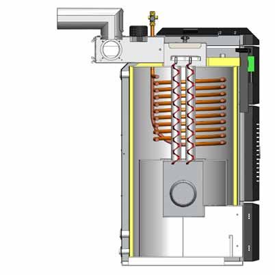
▀ Introduction

    We at Effecta would like to thank you for putting your trust in us when choosing your new
    boiler. The ”Effecta Komplett III” has been developed to give you maximum performance,
    comfort and quality. In order to get the best results from your boiler, we suggest that you
    follow the recommendations in this installation guide.

    Checking your delivery
    Check that the boiler has not been damaged during transportation. If the boiler has been
    damaged, you must report this to the transportation company immediately.

    Your safety
    If you discover any faults or defects in our products, it is important that you report them as
    quickly as possible to your installation engineer, so that the fault can be rectified. Make sure
    that there are no flammable materials close to the boiler, to help prevent risk of fire. You must
    use your own judgement when operating the pellet boiler. Remember that the hatches and
    some surfaces can get hot. You must take care to avoid being burnt.

    The user
    It is the user´s responsibility to operate the boiler according to our instructions. If you do
    not operate and maintain your boiler correctly, the environmental impact of the boiler will be
    greater, its efficency will be reduced and the service life of some components will be shorter.
    If there is anything that you are not sure about, please contact your installation engineer or
    Effecta for advice.

    Warranty
    The warranty takes effect from the date on which the boiler is installed. The supplied
    installation form must be completed and returned to Effecta. You can find the other guarantee
    terms on (page 3).

    ▀ Scope of delivery
    Please check all components delivered.
    The standard delivery as follows:
    - Effecta Komplett III boiler
    - Cleaning handle with brush
    - Rake with scraper
    - Flue attachment
    - Draft stabiliser
    - Turbulators, 8pcs.(mounted)
    - Drain cock
    - Shunt valve + motorized shunt control, not in ”Light” version
    - Electrical heater 3-9 kW (mounted), not in ”Light” version
    - Thermostatic mixer valve, not in ”Light” version
    - Room thermostat, optional in ”Light” version
    - Outdoor sensor, optional in ”Light” version

2           Effecta AB - Västra Rågdalsvägen 21 - 434 99 Kungsbacka - 0300 - 22320 - info@effecta.se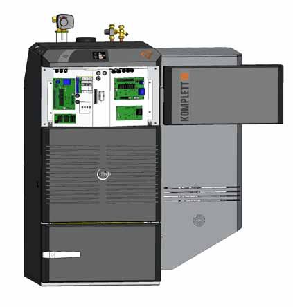
▀ Warranty
Effecta products are guaranteed to be free of defects in materials. The main body has a 5 year
warranty against leakage of water and all other parts have a 2 year warranty.
The warranty also covers original spare parts. Any faulty products will be replaced or repaired at
the discretion of the retailer or Effecta. If a faulty product is detected, Effecta is entitled to
replace it with a new or reconditioned product of the same or a similar type.
If you have a complaint, you must contact your retailer before starting any servicing work.You
must submit your complaint without delay. You must always state the type of product, the date of
purchase and the serial number.
Otherwise the heating and plumbing industry’s current regulations apply in case of complaints.

Guarantee terms:

The guarantee is valid on condition that:

-        The boiler and the heating system have been installed in accordance with the installation
         instructions and in a professional manner.
-        The location where the product is installed is suitable for purpose.

The guarantee does not cover:

-        The overall function of the heating system, costs incurred as a result of the heating
         system being out of operation, or the cost of the temporary replacement of products.
-        Damage or injury caused by negligence during the installation or by operating the boiler in
         a way which conflicts with the installation and user instructions.
-        Damage caused by abnormal wear, incorrect operation and maintenance.
-        Damage caused by the use of non-original spare parts.
-        Damage caused by the boiler being positioned in an unsuitable location.
-        Damage caused by vermin.

The terms may be different from country to country. Check with your installer.

▀ System data:
Installer:

Date:

Electrical installer:

         Effecta AB - Västra Rågdalsvägen 21 - 434 99 Kungsbacka - 0300 - 22320 - info@effecta.se      3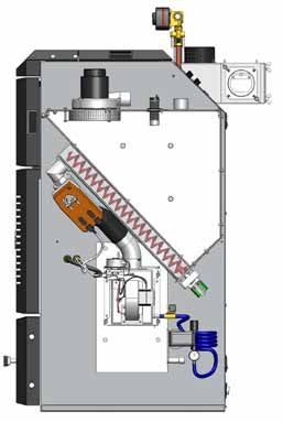
▀ Contents
    2    Introduction                                         43    Cleaning
    2    Scope of delivery                                    44    Cleaning and service
    3    Warranty                                             45    Service
    3    Warranty terms                                       46    Service
    3    System data                                          47    Adjusting door to ash compartment
    4    Contents                                             48    Troubleshooting
    5    In general                                           49    Documentation of settings
    5    Symbols in this document                             49    Technical data
    6    Your safety                                          50    Technical specification K3 external feeding
    7    Safety components                                    51    Technical specification K3 internal storage
    8    Components                                           52    Technical specification K3 suction system
    9    Fuel                                                 53    Connection suggestions internal hotwater and radiators
    10   Boiler room                                          54    Connection suggestions radiators and heaters
    11   Placement of components K3 external feeder           55    Connection suggestions accumulator tank with solar heating
    12   Placement of components K3 internal storage          56    Connection suggestions several heating cicuits
    13   Placement of components K3 vacuum system             57    Component placement K3
    14   Placement of components K3 vacuum system             58    Component placement K3
    15   Placement of components K3 internal storage          59    CE
    15   Placement of components K3 electrical system
    16   Placement of components K3 burner

    17   Cleaning system burner

    18   Cleaning system boiler

    19   Disassembly for move
    20   Function suction system
    21   Suction system and storage
    22   Installation of suction nozzles
    22   Installation of hoses
    23   Electrical connection
    24   Outlets of the circuit board
    25   Outlets of the circuit board
    26   Electrical Schematic
    27   Electrical Schematic
    28   The menu system
    29   The menu system
    30   The menu system
    31   The menu system
    32   The menu system
    32   Alarms
    32   Update software
    33   Tuning the boiler
    34   Tuning the boiler
    35   Hot water
    35   Valve combination
    36   Shunt control
    37   Tuning the boiler
    38   Examples of curves
    39   Mounting draft regulator
    40   Overheated fallshaft
    40   Replacing the combustion fan
    41   Replacing the igniter
    42   The chimney
    42   Flue attachment

4               Effecta AB - Västra Rågdalsvägen 21 - 434 99 Kungsbacka - 0300 - 22320 - info@effecta.se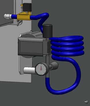
▀ In general
The boiler
Effecta Komplett III is a boiler which is to be fueled with wood pellets. No other kind of fuel is
allowed, not logs or oil.

Disassembly and disposal
It will be many years before your Effecta boiler is worn out, but it is important that you follow
the regulations in force at the time concerning disassembly and disposal of your boiler.

The fuel
The boiler should burn 6 mm ø pellets which come either in sacks or are supplied by bulk truck.
If you have built a bulk storage, you should follow the current recommendations to ensure that
the quality of the pellets does not deteriorate. Never use pellets which do not meet European
pellet standards DIN+, as this may result in problems in operating the burner.

▀ Symbols in this document
     Information
     This symbol is shown with to indicate important information the installer should know and
     understand. Neglecting this information can affect the performance of the product.

      Dangerous electricity
      This symbol means that extra caution should be taken otherwise serious personal injury
      might occur. When maintaining the product where this symbol is present the power must
      be disconnected. All electrical wiring must be done by a Professional and comply with
      current building regulations.
      Hot surfaces
      This symbol is shown when there is a risk of burns to people. Always wait for the boiler to
      cool down before you do any service.

       The product manual is a document that gets updated. You always find the latest version
       on our webpage www.effecta.se

        Effecta AB - Västra Rågdalsvägen 21 - 434 99 Kungsbacka - 0300 - 22320 - info@effecta.se     5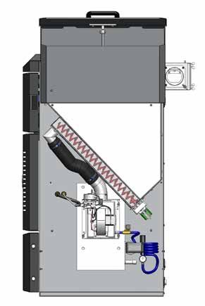
▀ Your safety

             Remember to always disconnect the power before working with the boiler.
             Wait until the boiler has cooled down before starting work.

    Before using the product, the owner and/or other user must read and understand the content
    in this manual. The directions must be followed. This is to make sure that the product is
    functioning correctly so accidents and injuries are avoided. Incorrect use or burner adjustment
    can result in damage to property and personal injury or poorer performance of the product.
    The boiler room where the product is installed, the chimney and other components must be
    approved according to current legislation.

    The commisioning of the product must be made by a professional, according to Effectas
    directions and current legislations. Controls and tuning of the product should be made by a
    professional. A chimney sweeper should also be contacted when commisioning the product.
    The electrical connections must be done by a qualified electrician, according to Effectas
    instructions in this manual.

    The casing outside of the burner must always be fitted on the boiler when the boiler is
    connected to the electrical power. Before cleaning and maintenance of the product, make sure
    it is disconnected from the main power.
    It is strictly forbidden to open any doors when the burner is igniting. If any door or hatch is
    opened when the burner is running, great caution must be taken. Any kind of interference or
    use of anything other than original spare parts can result in damage to the product or person. It
    also removes Effecta from any liability.

    It is strictly forbidden to make any changes or alterations to the boiler without prior approval
    from Effecta. If any changes are made, the safety functions, or any other function, might not
    work as it is supposed to, and all warranties and liabilites from Effecta are cancelled.

    This manual should be kept during the whole life span of the product. Any updates will be
    reported on the Effecta web page: www.effecta.se.

6           Effecta AB - Västra Rågdalsvägen 21 - 434 99 Kungsbacka - 0300 - 22320 - info@effecta.se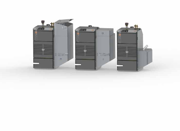
▀ Safety components
Drop tube
Between the storage and the feeder there is a meltable plastic tube which is
destroyed when it is overheated.

The overheat protection on the fall shaft
This stops the feeding and the fire damper if the fan temperatures gets
too high. Reset is made manually.The cover must always be in place when
connected to main power. It only cuts the power to the auger and fire damper.

Safety lock
If the boiler is equiped with a suction system there is a fire damper mounted.
This is closed during filling, overheating or loss of power.

Flame sensor
The flame sensor monitors the flame in the burner. If a valid value is lost for
more than 120sec the feeder stops. The burner is cooled down with maximum
rpm of the fan for (X) minutes before stopping. The pellets suction is not
allowed to start if the flame sensor detects light

Overheat protection on the boiler
There is overheat protection on the boiler which cuts the power to both the
boiler and the burner if the temperature in the boiler exceeds 95°C.

Compressed air cleaning
On the cleaning to the burner there are two safety systems. The controller
limits the the time the compressor is allowed to run, there is also a pressure
switch which closes the compressor when preinstalled pressure is reached.

Flue gas fan
A flue gas fan is mounted on the flue tube. The fan helps to maintain a stable
underpressure in the boiler and prevents back heat but also improves the com-
bustion. More on the fans adjustements are on pg. 33.

Door switch
The door switch stops the auger/feeder and no more pellets are fed into the
burner when the door to the combustion chamber is open.

Automatic fuses
Automatic fuses are installed in the electrical system, which are triggered if
there are any eletrical faults in the boiler. If triggered, an authorized electrician
should be contacted to determine the cause.

        Effecta AB - Västra Rågdalsvägen 21 - 434 99 Kungsbacka - 0300 - 22320 - info@effecta.se   7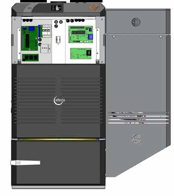
▀ Components
    The shunt valve
    The shunt valve is connected to the boiler or accumulator tank.The shunt valve
    controls the heat supply from the boiler to the heating circuits of the house.

    Heat regulation
    The boiler is equiped with its own heat regulator. In the ”Shunt control” menu you
    can choose how to control the heat in the house. More on how to regulate the
    heat is found on pg. 36.

    The thermostatic mixer valve
    The mixing valve is used to ensure that the temperature of the hot water in your
    shower and elsewhere in the house is comfortable. Set the system to the tem-
    perature you want by turning the thermostat between +/-. If you have a Komplett
    Light the mixer valve is mounted on the accumulator tank.

    Feeder
    The feeder is either internal or external on the boiler. The feeder controls the
    amount of pellets fed to the burner.

    The burner
    The burner is mounted on either the right or left side. The fuel from the feeder is
    ignited and combusted, which heats up the water in the boiler.

    Turbulators
    Within the tubes in the heat exchanger hang the turbulators. The turbulators function
    is to transfer heat from the flue gas to boiler water. They must always be placed in
    the boiler. If the flue gas temperature in the chimney is too low, the turbulators can
    be cut off to increase the temperature.

    Draft stabiliser
    The draft stabiliser gives the boiler stabile draft conditions, this improves
    combustion and efficiency.

    Hot water coil
    Within the boiler is a hot water coil that heats up the water for the house. The
    water you can drain from the boiler depends on the boiler temperature, the mount
    of flow you through and which effect the boiler is set to. We recommend a flow
    of 12-42l/min in the taps. In the Light model there is no coil, here you heat your
    water in a external water heater.

    The sealings
    The seals on the hatches must be checked every year. If the hatches do not seal
    properly, the efficiency and the combustion process of the boiler will deteriorate.
    Dust and ash can also leak out during cleaning.

8            Effecta AB - Västra Rågdalsvägen 21 - 434 99 Kungsbacka - 0300 - 22320 - info@effecta.se
▀ The fuel
Wood pellets are made of sawdust, a byproduct from handling wood. Wood contains lignin that
makes the pellet hard without any glue or other binder being used.

There are several different kinds of pellet on the market. The quality and energy can vary
between them. The diameter is 6-8mm, the normal length is between 5 and 30mm.
High quality pellets have a density of 600-750 kg/m3. The moisture content is 5-9% in weight.
Oil has an energy content of 9,9kWhr/kg and wood logs about 4,0kWhr/kg. Wood pellets have
a energy content of 4,7-5,0kWhr/kg. To maintain good combustion the pellets should be stored
in a dry place and be protected from dirt. Pellets are delivered in sacks with 10-15kg content or
in bulk by truck.

The Effecta Komplett III can handle most of the different types of wood pellets that are between
6-8mm, but in UK only 6mm should be used. The quality should meet DIN+ standards. Good
pellets with a small amount of dust and that are uniform helps achieve good combustion, less
maintenance of the product and also less environmentally harmful emissions.

The worse the quality of fuel is, the more cleaning and maintenance of the product will be
required.

          The amount of pellets fed into the burner should be controlled every time the pellet
          brand or quality is changed. If the deviation is more than 0,5kg/hour compared to the
          numbers in the ”Warranty and Installation” paper, the burner should be tuned.

       Effecta AB - Västra Rågdalsvägen 21 - 434 99 Kungsbacka - 0300 - 22320 - info@effecta.se     9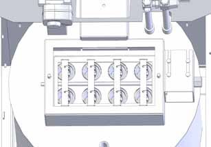
▀ Boiler room

     It is time to install the Effecta Komplett III pellet boiler. Please follow the examples we provide
     for a safe installation. After installation, be sure to instruct the customer on how the heating
     system and the boiler works, in order to avoid unnecessary complications in the future.

     Set up
     The boiler is positioned so that the
     surface temperature of flammable
     building material does not exceed
     80°C. The boiler should be positioned
     at least 10 cm (1) from the wall. If the
     distance between the flue tube and
     flammable wall is less than 30 cm
     an ignition protective covering
     must be used (4). In order to
     clean the boiler, a minimum
     clear space of 1 metre (2)
     is required in front of the
     boiler. A passage with a
     minimum width of 0.5m (3)
     is required along one of
     the long sides of the boiler.
     Check the regulations of your
     country in order to place the
     pellet hopper an approved
     distance from the boiler.

     Boiler room
     The boiler must be installed in a boiler room or boiler house. The ceilings and walls must
     be fitted with ignition protective covering and the floor must be made of non-combustible
     material. Minimum ceiling height in the boiler room is 2 metres. The boiler room or boiler house
     must be equipped with a fresh air intake with the minimum dimensions 150 x 150 mm(5.) or
     with a sufficiently large free sectional area to avoid low pressure in the boiler room. It must be
     impossible to close the air intake.

     Chimney
     The chimney should have enough area to manage the effect from the boiler. At standstill the draft
     should be between 5-10pa. It is important that the chimney is tested and approved by a HETAS
     approved installer before a new boiler is installed. If the chimney is tall and has a lot of mass to
     heat up there is a risk of condensation. Measure the temperature 1m down from the top when the
     burner is running, the temperature should be 70°C.
     Read more about the chimney on pg 42.

10           Effecta AB - Västra Rågdalsvägen 21 - 434 99 Kungsbacka - 0300 - 22320 - info@effecta.se
▀ Placement of components K3 external feeder
Front Back Top
1 Adjustable feet 1 Drain cock 1 Flue gas measuring point
2 Ash door 2 Return hot water circuit 2 Boiler fan
3 Door switch 3 Flow hot water circuit 3 Cleaning access
4 Front cover 4 Hoses electrical wiring 4 Flue connection
5 Handle Front cover 5 Shunt valve* 5 Draft stabiliser
6 Display 6 Conduit for sensor
7 Fall shaft pellet burner 7 Connector feed motor/auger * Not on Light
8 Protective cover 8 Mixing valve * for hot water
Effecta AB - Västra Rågdalsvägen 21 - 434 99 Kungsbacka - 0300 - 22320 - info@effecta.se 11▀ Placement of components K3 internal storage
Front Back Top
1 Adjustable feet 1 Drain cock 1 Flue gas measuring point
2 Ash door 2 Return hot water circuit 2 Boiler fan
3 Handle ash door 3 Flow hot water circuit 3 Cleaning access
4 Front cover 4 Hoses electrical wiring 4 Flue connection
5 Handle Front cover 5 Shunt valve* 5 Handle storage lid
6 Display 6 Conduit for sensor
7 Gas damper 7 Connector feed motor/auger * Not on Light
8 Internal storage 8 Mixing valve * for hot water
12 Effecta AB - Västra Rågdalsvägen 21 - 434 99 Kungsbacka - 0300 - 22320 - info@effecta.se▀ Placement of components K3 vacuum system
Front Back Top
1 Adjustable feet 1 Drain cock 1 Flue gas measuring point
2 Ash door 2 Return hot water circuit 2 Boiler fan
3 Handle ash door 3 Flow hot water circuit 3 Cleaning access
4 Front cover 4 Hoses electrical wiring 4 Flue connection
5 Handle Front cover 5 Shunt valve* 5 Draft stabiliser
6 Display 6 Conduit for sensor
7 Insulated cover plate 7 Connector feed motor/auger * Not on Light
8 Lower cover plate 8 Mixing valve * for hot water
Effecta AB - Västra Rågdalsvägen 21 - 434 99 Kungsbacka - 0300 - 22320 - info@effecta.se 13▀ Placement of components K3 vacuum system
Side Front Top
1 Meltable plastic tube 1 Fallshaft 1 Vacuum fan
2 Safety ball valve 2 Safety lock 2 Connection hose suction nozzle
3 Internal feeder 3 Capacitive sensor
4 Internal feed motor 4 Connection for filling pellets
14 Effecta AB - Västra Rågdalsvägen 21 - 434 99 Kungsbacka - 0300 - 22320 - info@effecta.se▀ Placement of components K3 internal storage
1 Hose clamp 2pcs
2 Meltable plastic tube
3 Handle storage lid
4 Gas damper
5 Internal storage
6 Internal feeder
7 Internal feed motor
▀ Placement of components K3 electrical system
1 Motherboard
2 Card electrical heater
3 Terminal block N and PE
VARNING LIVSFARLIG SPÄNNING
WARNING DANGEROUS VOLTAGE
ACHTUNG GEFÄHRLICHE SPANNUNG
AVERTISSEMENT TENSION DANGEREUSE
4 Power supply boiler 20A fuse
5 USB connection for updating software
VARNING LIVSFARLIG SPÄNNING
WARNING DANGEROUS VOLTAGE
ACHTUNG GEFÄHRLICHE SPANNUNG
AVERTISSEMENT TENSION DANGEREUSE
6 Capacitor underpressure fan
VARNING LIVSFARLIG SPÄNNING
WARNING DANGEROUS VOLTAGE
ACHTUNG GEFÄHRLICHE SPANNUNG
AVERTISSEMENT TENSION DANGEREUSE
7 Expansion board
8 Lambda board
9 Mechanical overheat protection
Effecta AB - Västra Rågdalsvägen 21 - 434 99 Kungsbacka - 0300 - 22320 - info@effecta.se 15▀ Placement of components K3 burner
Side Front Top
1 Outer tube 1 Combustion tube 1 Connection compressed air
2 Fallshaft 2 Fallout pellets 2 Connection flame sensor
3 Overheat protection fall shaft 3 Flame sensor hole 3 Power to the burner
4 Combustion fan 4 Hole for ignition element
5 Flame sensor 5 Hole for compressed air
6 Ignition console
7 Blowpipe to the compressor
16 Effecta AB - Västra Rågdalsvägen 21 - 434 99 Kungsbacka - 0300 - 22320 - info@effecta.se▀ Cleaning system burner
Remember to always cut the power to the boiler before starting any work on it.
Function
On the side of the burner there is a compressor with a compressed air hose mounted which
cleans the burner. Compressed air is blown into the burner. When the cleaning starts the com-
pressor builds up a pressure in the hose which then is released with a pressure shock and the
ashes are removed from the burner. You can set how often, how long and during which times
cleaning is allowed in the ”SERVICE”menu.
Compressor
The compressor builds up a pressure in the air hose.
The compressor has a life span of about 2500h, and
can then drop in pressure head or leak air. Then there
is a renovation set to renovate the compressor.
Compressed air hose
The hose is only used to store air before it is
released into the burner.
Pressure gauge
Shows the pressure in the hose. It is also an
indicator when or if you need to adjust the pressure
for optimisation.
Pressure switch
Stops the compressor when targeted pressure
is reached, there is a adjustment screw which is
preset on 7 bar.
1 Compressor
2 Capacitor
3 Pressure switch
4 Pressure gauge
5 Solenoid valve
6 Compressed air hose
Effecta AB - Västra Rågdalsvägen 21 - 434 99 Kungsbacka - 0300 - 22320 - info@effecta.se 17▀ Cleaning system boiler
Remember to always cut the power to the boiler before starting any
work on it.
Function
On the boiler there is an magnet motor which does the maintenance and ash cleaning of the con-
vection section. The magnet is controlled from the ”Cleaning” menu, there you can set the times
it allowed to clean. The magnet is relatively quiet, and if it doesn´t disturb it should be allowed to
clean around the clock.
Magnet
The magnet is mounted on the right side of the boi-
ler. The magnet lifts the turbulators in the tubes.
Lifting shaft
Rotating the lift shaft lifts the turbulators and clean
the tubes.
Turbulators
The turbulators in the tube help by reducing the flue
gas temperature and also cleaning the tubes when
pulled up and down.
Suspension
On every suspension there are two turbulators
that are removed when cleaning the tubes with
a brush.
Flipper
Flips when the magnet motor activates.
1 Magnet
2 Lifting shaft
3 Flipper
4 Susoension
5 Turbulator
18 Effecta AB - Västra Rågdalsvägen 21 - 434 99 Kungsbacka - 0300 - 22320 - info@effecta.se▀ Disassembly for move
The boiler is fully mounted when delivered. If the boilers width exceed the door you can
disassemble it to a smaller size
Remove the cover of the suc- Then remove the 4 plastic Loosen the 4 screws and
tion system. If the boiler has covers which conceals the remove the cover plates.
an internal storage remove screws for the cover plates.
the screws which holds the They hold the coverplates to
top part. the internal storage.
Loosen the bolts to the lid. If the boiler has a suction sys- Unscrew the 3 bolts holding
Remember to disconnect all tem disconnect the safety ball the storage and remove it.
the cables to the suction sys- valve. Loosen the hose clamp
tem before you remove the lid on the fall shaft. Loosen the
2 nuts which holds the safety
ball valve to the storage and
remove it all.
If there is an internal storage
just remove the hose.
Disconnect all the cables to
the burner. Then unscrew the Make sure when you reassemble the storage that all
4 bolts which holds the burner hose clamps and other sealings are tight. Leakage will
plate to the boiler. Remove cause disruptions due to there being no underpressure.
the burner straight out.
Effecta AB - Västra Rågdalsvägen 21 - 434 99 Kungsbacka - 0300 - 22320 - info@effecta.se 19▀ Function suction system
If the boiler is equipped with a suction I n -
Filling interval 8h stal-
system the menu on the right is shown. Night blockage Yes lation
In the ”INSTALLATION” menu you need to Fill storage No
change settings in order to customize the
system for your energy needs.
Function
The suction system includes a number of Consumption
important components. On the storage kW/h kW/day Time filling, h
there is a suction motor which builds up a 5 120 30
underpressure in the hose connected to the 10 240 15
filling outlet of the storage. The proximity 15 360 10
sensor senses the need for filling pellets, 20 480 8
when set time between fillings is reached, 25 600 6
the safety ball valve closes and the suction
system is allowed to start, with a delay of
60sec. The suction motor tries to fill the storage by running for 15min - resting for 15min - running
for 15min and so on. If the storage hasn´t been filled after 80mins the boiler alarms ”Suction
time”. A filling normally takes 15-20min suction time.
Time between fillings
How often your system chooses to fill is down to your settings in the menu. We recommend you
set it as far a part you can, but with a margin so that the storage never is empty. A full storage
contains roughly 200kWh of energy. If your house consumes 8kWh, the storage last for about
24hours.
Night blocking
If the boiler is placed so you can hear it, you can block refilling of pellets certain times of the day.
In the ”SERVICE” menu you can set when refilling is allowed(On) and when its not allowed(Off).
Then refilling isn´t allowed between these hours, unless there is a risk of downtime of the burner,
in which case the filling cycle runs even though you have turned it off.
Fill storage
If you activate ”Fill Storage”, the storage will be filled regardless of settings. This function is
used when you first start the system or if the storage is empty. Note that if the storage has been
emptied, the feeder must be filled again. In the ”Installation” menu you find the function ”Fill
feeder”. The boiler must be in mode ”Off” for this function.
Proximity sensor
The proximity sensor is mounted from the factory. When the
light is on there are pellets near the top of the storage. If the
sensor needs to be adjusted it should be done when the storage is
full. Find the setting for On/Off on the screw. Adjust it so that the
light is lit.
20 Effecta AB - Västra Rågdalsvägen 21 - 434 99 Kungsbacka - 0300 - 22320 - info@effecta.se▀ Suction system and storage
Storage
If you build your own storage make sure that the walls can take the pressure of the pellets. It
is also important that the storage is completely tight so that it does not allow dust to escape.
An inspection hatch must also be installed so that you can serve and clean the storage when
needed.
Suction nozzle 1 Suction to boiler
In your system you need to install one or more 2 Return from boiler
suction nozzles. The nozzle collect pellets from 3 Mounting plate
storage via the suction hose that is connected inclined wall
to the internal storage. The number of nozzles 4 Mounting plate floor
needed depends one the size and shape of the 5 Return nozzle
storage.On pg 22 you can see how to place
them.
Switch
1 Suction to boiler
For every nozzle you need a switch. The switch
2 Return from boiler
is placed on the storage. If several nozzles
are installed you complement the switch with 3 Cover plate
a connector and a cover plate. When the 4 Suction nozzle
pellets have ran out at a nozzle you just switch 5 Return nozzle
connector.
1 Suction nozzle 3 Connector
2 Hose clamp 4 Hose for return
5 Hose
Effecta AB - Västra Rågdalsvägen 21 - 434 99 Kungsbacka - 0300 - 22320 - info@effecta.se 21▀ Installation of suction nozzles
Regardless of the number of nozzles installed there will always be a certain amount of
pellets left in the bottom of the storage.
The nozzles are designed so that they can be mounted on the bottom of a flat storage or in a
storage with a sloped wall. It is important that the slope of the wall is 45º so that the mounting
plate comes in at the right angle. Make sure to seal behind the mounting plate so no dust can
leak out. When the nozzle is placed on the bottom of the storage it is important that it is bolted
firmly due to the pressure it has to take when the storage is filled with pellets.
Flat bottom
When placing the nozzles on the bottom you
600
need to decide how many to place. We re-
600 commend a distance of 600mm from wall and
1200
1200 1200mm between the nozzles. It is possible to
place them further apart but it effects the ability
to empty the storage completely.
Sloped wall
In a storage with sloped walls we recommed a
distance between the nozzles of 1200mm and
600mm from a vertical wall. The wall the nozzle
is to be mounted on must have a slope of 45º.
1200
600
600
▀ Mounting of hoses
When mounting the hoses make sure that all connections are tight. The hoses must
also be grounded to avoid static electricity.
The suction motor on the boilers storage
Max 12m
has limitations in which underpressure it can
produce. Therefore, it is important that the
hoses between the switch and the boiler are
not too long. We can guarantee the function
Max 3.5m
according to the distances on the sketch, if you
want a longer distance there is a risk for reduced
feeding and disruptions to the boiler. It is
paramount that the connections against nozzles
and switches are tight. If there are leaks, the
suction capacity deteriorates significantly.
Max 15m
22 Effecta AB - Västra Rågdalsvägen 21 - 434 99 Kungsbacka - 0300 - 22320 - info@effecta.se▀ Electrical connection
NOTE! The boiler must be filled with water before the wiring begins.
For wiring to the motherboard you need to use a standard
screwdriver with a tip width of 3mm and a length of about
12cm. You can open the spring load of the motherboard in
both the tracks that are on every cable entry.
3m
m
When it’s time to do the electrical connection you need to
remove the front casing which is in front of the motherboard.
On the backside of the boiler there are eight (1) conduits
that end in the front of the boiler. These are used to connect
the sensors and electrical cables. Don’t put the low and
high voltage in the same hose, it can effect the showing of
temperature. To remove the front casing, grab the two handles
and pull it straight out, hard. Then connect the input voltage to
the card’s ports.
Power guard
If the electricity comsumption is high in the pro-
perty while the electrical heater is
operating there is a risk that the pro-
pertys main fuses will blow. The Effecta
Komplett III is equipped with a power
guard which prevents electrical over-
load by redistributing the power supply
between the phases.
Connection of current sensors VARNING LIVSFARLIG SPÄNNING
WARNING DANGEROUS VOLTAGE
To measure the power you must install
ACHTUNG GEFÄHRLICHE SPANNUNG
AVERTISSEMENT TENSION DANGEREUSE
VARNING LIVSFARLIG SPÄNNING
WARNING DANGEROUS VOLTAGE
ACHTUNG GEFÄHRLICHE SPANNUNG
AVERTISSEMENT TENSION DANGEREUSE
one current sensor to each incoming
VARNING LIVSFARLIG SPÄNNING
WARNING DANGEROUS VOLTAGE
ACHTUNG GEFÄHRLICHE SPANNUNG
AVERTISSEMENT TENSION DANGEREUSE
phase in the house. This must be done
directly in the electrical control. Con-
nect the sensors to a cable with the
area of 0,5mm2 to the circuit board. In
the “electrical heater” menu you set
the max power that’s allowed on the
fuses in your house.
Effecta AB - Västra Rågdalsvägen 21 - 434 99 Kungsbacka - 0300 - 22320 - info@effecta.se 23▀ Outlets of the motherboard
Remember to always cut the power to the boiler before starting any work
on it. All electrical work should be done by a certified electrician, for your
safety.
Mother board
G1 Temp sensor boiler NTC 22 kΩ PE Earth
G2 Sensor flue gas PT1000 N Zero
G3 Extern control L1 Incoming phase 6,3 A/230 VAC
G4 Tacho meter PE Earth
G5 Sensor accumulator tank low NTC 22 kΩ N Zero
G6 Sensor accumulator tank high NTC 22 kΩ 11 Radiator pump 2A/230 VAC
G7 Flow sensor NTC 22 kΩ 12 Shunt motor 2A / 230 VAC
G8 Flame sensor N Zero
1U. Connection to display board 13 Shunt motor 2A/230 VAC
2U. Connection to electricity board PE Earth
N Zero
1. Outdoor sensor 14 Solenoid valve AERO 2A/230 VAC
2. Outdoor sensor PE Earth
3. Room sensor shunt group (1) N Zero
4. Room sensor shunt group (2) 15 Compressor 2A/ 230 VAC
5. Room sensor shunt group (3) PE Earth
N Zero
52 16 Magnet motor 2A/230 VAC
53 Tachometer N Zero
54 Tachometer 17 Loading pump 2A/230 VAC
55 Amperemeter N Zero
56 Amperemeter 18 Alarm 230 VAC
57 Amperemeter 19 Alarm - closed on larm
58 Joint 20 Alarm - closed on larm
Lambda board
1 Lambda White
2. Lambda Brown
3. Lambda Black
4. Lambda Red
5. Lambda Grey
6. Lambda Blue
N Power Zero 230 VAC
L Poiwer Phase 230 VAC
24 Effecta AB - Västra Rågdalsvägen 21 - 434 99 Kungsbacka - 0300 - 22320 - info@effecta.se▀ Outlets of the expansion card
Remember to always cut the power to the boiler before starting any work
on it. All electrical work should be done by a certified electrician, for your
safety.
Expansion card
G9 Flow sensor shunt group 2 NTC 22 kΩ L1 Incoming 230 VAC
G10 Flow sensor shunt group 3 NTC 22 kΩ N Zero
G11 Flow sensor energy measuring 1 NTC 22 kΩ PE Earth
G12 Flow sensor energy measuring 2 NTC 22 kΩ PE Earth
G13 Flow sensor energy measuring 3 NTC 22 kΩ N Zero
G14 Flow sensor energy measuring 4 NTC 22 kΩ 19 Radiatorpump shunt group 2 / 2A/230 VAC
G15 Flow sensor loading circuit NTC 22 kΩ PE Earth
G16 --- N Zero
G17 --- 20 Radiatorpump shuntgroup 3 / 2A/230 VAC
G18 --- 21 Shunt motor group 2 / 2A / 230 VAC
G19 --- N Zero
1 Flowmeter 1-5 22 Shunt motor group 2 / 2A / 230 VAC
2. Flowmeter 1-5 23 Shunt motor group 3 / 2A / 230 VAC
3. Flowmeter 1-5 N Zero
4. Flowmeter 1-5 24 Shunt motor group 3 / 2A / 230 VAC
PE Earth
64. Room sensor shunt group 2 (1) N Zero
65. Room sensor shunt group 2 (2) 25 Suction motor
66. Room sensor shunt group 2 (3) PE Earth
67. Room sensor shunt group 3 (1) N Zero
68. Room sensor shunt group 3 (2) 26 Safety ball valve 2A / 230 VAC
69. Room sensor shunt group 3 (3) PE Earth
70. Port free - N Zero
71. Port free + 27 Pump loading circuit 2A / 230 VAC
72. Proximity sensor internal (Brown) PE Earth
73. Proximity sensor internal (Black) N Zero
74. Proximity sensor internal (Blue) 28 Additional fan speed controlled 2A / 230 VAC
75. Proximity sensor internal (White) 29 Extra valve 2A / 230 VAC
76. Proximity sensor external (Brown) N Zero
77. Proximity sensor external (Black) 30 Extra valve 2A / 230 VAC
78. Proximity sensor external (Blue) -- --
79. Proximity sensor external (White) -- --
Effecta AB - Västra Rågdalsvägen 21 - 434 99 Kungsbacka - 0300 - 22320 - info@effecta.se 2526
N
▀ Electrical schematic
N
EXPANSION CARD EL.HEATER
AUTOMATIC FUSE 20 A
EL 3a EL 3b
OVER HEAT PROTECTION 95 ˚C
L3
POWER 230 V
SENSOR
ROOM
OUT DOOR
123
ROOM SENSOR 1
EL 2a EL 2b
L2
EL 1a EL 1b
L1
ALARM
ALARM
18
6
5
4
3
2
1
N WN
BRO
17 E
LOADINGPUMP
BLU
EL
N
16 BROWN
FLAME SENSOR G8
N BLUE
TUBE CLEANING
M
FLOW SENSOR G7 PE EARTH
N
ACC. HIGH 15
L1
L3
L2
G6 BROWN
N COMPRESSOR
EARTH
BLUE
M
ACC. LOW
G5 PE EARTH
TACHOMETER VIT G4 14 BROWN
G3 N SOLENOID VALVE
EXTERNAL CONTROL BLUE
PE EARTH
FLUE GAS G2
13 OPEN
BOILER TEMP G1
N NEUTRAL SHUNT MOTOR
12 CLOSED
M
MOTHER BOARD
11 BROWN
N BLUE
RADIATOR PUMP
Effecta AB - Västra Rågdalsvägen 21 - 434 99 Kungsbacka - 0300 - 22320 - info@effecta.se
PE EARTH
L1
N
PE
EA
RT
H
Display Expansion board
BROWN
52 24
TACHOMETER SVART 53 23
BLUE
M
TACHOMETER RÖD 54 22
55 21
AMPERE METER 56 N
57
LOW VOLTAGE
BOILER FAN
JOINT 58
CONDENSATOR
HIGH VOLTAGE 230 VAC
EARTHMIXER MOTOR ACCUMULATOR
EXTRA -RPM CONTROLLED
FAN - RPM CONTROLLED
SAFETY BALL MOTOR
SUCTION MOTOR
RADIATOR PUMP
RADIATOR PUMP
LOADING PUMP
SHUNT MOTOR
SHUNT MOTOR
M M M M M
PE
PE
27
PE
22
28
L1
21
PE
20
PE
PE
26
24
25
19
30
PE
29
23
PE
PE
N
N
N
N
N
N
N
N
N
N
N
MOTHER BOARD
LAMBDA CARD
SAFETY MOTOR
EXPANSION BOARD
SWITCH
1 2 3 4 5 HIGH VOLTAGE 230 VAC
4
LOW VOLTAGE
ENERGY MEASURING
3 1 2 3 4 5
61
61
60
60
59
59
1 2 3 4 5
G19
G18
G17
G16
G11
G15
G12
G14
G13
G10
2
G9
POT FREE
72
73
74
76
77
78
66
64
65
69
70
75
79
71
68
67
1 2 3 4 5
1
-
+
BROWN
BLACK
WHITE
BLUE
123 123
ROOM
ROOM
ENERGY MEASURING1
ENERGY MEASURING 2
ENERGY MEASURING 3
ENERGY MEASURING 4
FLOW
FLOW
PROXIMITY SENSOR
ROOM SENSOR 2
ROOM SENSOR 3
EARTH CENTER SOCKET
EARTH CENTER PIN
1 2 3 45 6 78
5.
2.
6.
FAN MOTOR
IGNITER
FEEDER
OVERHEAT PROTECTION M M WHITE
1
LAMBDA CARD
L1
N
FALLSHAFT BROWN
2
1.
BLACK
3
RED
3.
GREY
4
4.
BLUE
5
6
TACHO METER
P
WHITE G4
BLACK 53
RED 54
DOOR
SWITCH
USB
DISPLAY EFFECTA AB
Västra Rågdalsvägen 21 - 43496 kungsbacka
Tel: 0300-22320 - Fax: 0300-22395
E-post:info@effecta.se - www.effecta.se
DAT: RITAD AV:
014-02-06 Erik Andersson
CIRCUIT DIAGRAM
EFFECTA KOMPLETT
ELECTRICAL HEATER 3+3+3 KW
50-12-11
Effecta AB - Västra Rågdalsvägen 21 - 434 99 Kungsbacka - 0300 - 22320 - info@effecta.se 27▀ Menu system
1. Flue temp.
2. Flow temp.
3. Boiler temp.
4. CO2
5. Flame sens.
6. El.heater
7. Igniter
OPERATION HEATING SYSTEM OTHER
Operation settings System settings Other settings
Burner Off Weekday >
Fan Shunt group 1 > Time >
Feeder settings Calib. sensors >
Shunt group 2 >
Temperature set Function test >
Shunt group 3 >
Information Alarms >
El. heater
Service English >
Installation Start guide >
VER: 3.0
Fan Shunt control
Fan burner % Sensor Room Calib.sensors
Fan boiler % Room temp 20.0 (18.2)°C
Fan lowspeed Sensor G1 0°C
Ja Flow temp 10°C Sensor G2 0°C
Fan lowspeed burner % Radiator pump Yes Sensor G3 0°C
Fan lowspeed burner %
Max flow temp. 60°C Sensor G4 0°C
Fan larm Tacho
Min. flow temp 10°C Sensor G5 0°C
Fan larm 5s
Max room temp 25°C Sensor G6 0°C
Min room temp 15°C Sensor G8 0°C
Heating off 16°C Sensor G8 0°C
Outdoor temp -8°C Outdoor 0°C
Feeder settings Heat curve Indoor 0°C
Start dose 65s Slope 40°C
Support dose 10s Adjustment 0°C
Pellets diameter mm Energysaver > Function test
Run start dose kW DHW Priority No Flame sens. 0%
Run supp. dose Igniter OFF
Run oper. dose Feeder OFF
Shunt group 2 & 3 Fan 0%
Sensor Constant flow Compressor OFF
Flow temp. (18.2)°C 10°C Solenoid valve OFF
Flow temp. Ja Test air cleaning OFF
Radiator pump 60°C Convection clean OFF
Temperature set Max flow 10°C Shunt motor (+/-) OFF
Boiler temp G1 °C Min. flow 25°C Electrical heater 0
Acc. high G5 °C Max room temp 15°C Radiator pump OFF
Acc. low G6 °C Min room temp 16°C Loading pump OFF
Stop G5 °C Flue gas fan 0%
Start G6 °C
max G1 °C El. heater
Loading pump Start °C El.step (A-B-C) till
Loading pump Stop m
Power outlet A 0(16)
Alarms
El. heater 6 kW 0h
Ignition failure 23
El. heater 3 kW 0h
Information Start phase failure 12
Burner starts 100st Oper. phase failure 3
Igniter hours 10h
Oper. pellets 100h
Clean number 130st
Reset info no
Energy saver
Lowering temp - 5 °C
Service Advanced Mon 06 _ _ _ _ 22
Clean at Phase out. FanPulse 1 20% Tue 06 _ _ _ _ 22
On 09:00 FanPulse 2 20% Wed 06 _ _ _ _ 22
Off 22:00 FanPulse 3 20% Thu 06 _ _ _ _ 22
Interval 2 Fan start 60s Fri 06 _ _ _ _ 22
Number clean 2 Oper. Phase start 60s Sat 06 _ _ _ _ 22
Clean pause 40s Burner starts 100st Sun 06 _ _ _ _ 22
Cleaning conv. 3st Igniter hours 10h
Flue gas 90°C Oper pellet 100h
Max time burner 3h Ign. sequence 1 0
Ext. contr. Off Ign. sequence 2 0
Ign. sequence 3 2
Installation DHW Priority (A) Ja
Advanced > Flame sens. Temp. G1 min 50°C
Fill feeder No Level start 80% Max flow temp 20°C
Effect high speed 0s Level oper. 40%
Effect low speed 20s Time oper. 120s
Testblow start 50% Time phase out 120s
Phase out 120s
Fan pre oper. 120s
Fan low pre oper.
Flame sensor
Quickstart
Lambda
Quick start
Lambdasond Temp. down 20°C
Lambda ja Temp. down 3
co2 12.0%
Calibration sensor 0.0%
28 Effecta AB - Västra Rågdalsvägen 21 - 434 99 Kungsbacka - 0300 - 22320 - info@effecta.se▀ Menu system
1. Flue gas temp. Current temperature of the flue gases G2
2. Flow temp. Current temperature of the flow G7
3. Boiler temp. Current boiler temperature G1
4. CO2 Current CO2 value
5. Flame sensor Current strength of flame in boiler.
6. El. heater Current effect of the el. heater in the boiler.
7. Igniter Current burner mode.
Operation Settings for burner.
Heating system Settings for heating systems.
Other Settings for other functions
Burner > Burner mode (on/off)
Fan > Settings for the fan of the burner.
Feeder > Settings of the augers feeding control. (password needed)
Temperature set > Settings for the burners operation temp.
Information > Operations log of the burner.
Service > Menu for burner service settings.
Installation >
Settings for automatic cleaning etc.
► Fan
Fan burner Setting of the burner fan in operation mode.
Fan boiler Setting of the boiler fan in lowspeed.
Fan lowspeed On Activating low speed (On/Off)
Fan burner lowspeed Settings of burner fan in lowspeed.
Fan boiler lowspeed Settings of boiler fan in lowspeed.
Fan larm Tacho Activates Tacho mode
Fan larm 5s Time before alarm triggers
► Feeder
Start dose Start dose size, measured according to (pg.33.)
Support dose Size of support dose, dose is given between ignition and running mode.
Pellets diameter mm Size of the pellet
Run start dose Test run of start dose for measuring. Only available in burner mode off.
Run supp. dose Test run of supp. dose for measuring. Only available in burner mode off.
Run oper. dose Test run of operation dose for measuring. Only available in burner mode off.
► Temperature set
Boiler temp G1 Shows the boiler temp, start/stop sensor with overheating function.
Stop Temperature when the burner goes to standby mode.
Start Temperature when the burner starts up from standby mode.
Acc.tank high G6 When loading acc. tank, sensor G6 is installed at the tank top of the primary
Acc.tank low G5 tank. The sensor starts the burner at set temp. (Only shown if mounted)
Stop G5 Temperature when burner stops.
Max G6 Maximum allowed temperature G6, tank overheated.
Start G1 Temperature when burner starts.
Loading pump Start Temperature when loading pump starts
Loading pump Stop Time loading pump runs
►Information
Number starts Displays the number of burner starts been done
Igniter hours Displays the number of hours ignitor has been lit.
Oper. pellets Displays the number of hours the burners been running.
Clean number Displays the number of times the AERO unit has cleaned the burner.
Reset info Resets the information above.
Effecta AB - Västra Rågdalsvägen 21 - 434 99 Kungsbacka - 0300 - 22320 - info@effecta.se 29▀ Menu system
► Service
Clean at phase out. Option if cleaning should be done prior to or after the running cycle.
On Time when AERO cleaning is allowed (ON).
Off Time when AERO cleaning is not allowed (OFF).
Interval Setting of how many cleaning cycles.
Number clean Setting of the amount of blows in each cycle.
Clean pause Time between each blow in a cleaning cycle.
Cleaning conv. Settings for cleaning the convection
Flue gas Temperature for the cleaning to start.
Max time burner Max operation time of the burner before pause with AERO cleaning
External control Off Choice of external START/STOP control to the boiler
► Installation
Advanced > Advanced settings (requires password)
Fill feeeder Activates feeder for 15min. Only in mode Burner Off.
Effect high speed Setting for the burners effect in high speed.
Effect low speed Setting for the burners effect in low speed.
Testblow Seconds the fan blows before ignition phase.
Phase out Seconds the ignitor is active after the flame sensor has approved start value.
Fan pre oper. The fan speed before operation phase.
Fan low pre oper. The fan low speed before operation phase.
Clean phase out Time that the fan afterblows before standby or cleaning.
Flame sens > To flame sensor menu
Quickstart > To quick start menu
Lambda > To Lambda menu
Time between filling Time between fillings
Night block Time when filling is not allowed.
Fill storage Manually filling of the storage
► Flame sensor
Level start Set value where the burner goes from ignition mode to operation mode.
Level oper. Lowest approved value in operation mode. If lower: ”ALARM BURNER”
Time oper Time before ”ALARM BURNER” when flame sensor lower than level oper.
Time phase out Time before the fan goes to max speed.
► Snabbstart
Temp down °C Degrees temp shall fall before burner goes to quick start.
Temp down min The time in which the temp. shall fall (X) degrees before burner activates quickstart.
► Lambda
co2 level % Settings of required oxygen level in combustion.
Calibrate % Possible calibration of lambda +/-.
► Advance
FanPulse 1 Fan speed in Fan Pulse 1.
FanPulse 2 Fan speed in Fan Pulse 2.
FanPulse 3 Fan speed in Fan Pulse 3.
Fan start Time before the fan starts.
Oper. start Time before the burner goes into operation.
Burner starts Number of registrated ignitions.
Igniter hours Number of hours the igniter has operated
Oper. pellets Number of hours the burner has operated.
Number clean Number of starts the compressor has done
Ign. Sequence 1 Registration of which Ign. sequence ignition occurs.
Ign. Sequence 2
Ign. Sequence 3
30 Effecta AB - Västra Rågdalsvägen 21 - 434 99 Kungsbacka - 0300 - 22320 - info@effecta.se▀ Menu system
► Heating system
Shunt group 1 > Selection of shunt group
Shunt group 2 > Selection of shunt group
Shunt group 3 > Selection of shunt group
El. heater > Settings for the electrical heater
► Shunt control
Sensor Option of control.
Room temp Settings of the room temperature
Flow. temp. Temp. to radiator/underfloor heating.
Radiator pump Activates radiator pump.
Max flow temp Maximum allowed temperature to the flow.
Min flow temp Minimum allowed flow temp.
Max room temp. Maximum allowed room temp.
Min room temp. Minimum allowed room temp. Shunt opens full at set temp.
Heating off Outdoor temp when heating turns off. Rad. pump is runned 1min/2hours.
Outdoor temp Outdoor temperature at the outdoor sensor
Heat curve The heating curve for the heating control (pg.36-38).
Slope Option of slope to the heat curve (pg.36-38.).
Adjustment Option of adjustment to the heat curve (pg.36-38.).
Energy saver > Options for energy saver
DHW Priority > Options for DHW Priority
► Shunt group 1 & 2
Sensor Option of control
Flow. temp. Flow temperature
Radiator pump Activates radiator pump.
-Current control- Selection of system
Energy saver > Options for energy saver
DHW Priority > Options for DHW Priority
►Energy saver
Lowering temp. - 5 °C Weekly Schedule when the indoor temperature is lowered by a number of
degrees.
Mon 06 _ _ _ _ 22 Example: At 06 returns to normal temperature and to be lowered again at 22.
Tue 06 12 16 22 Example: At 06 returns to normal, lowered at12 and at 16 returns to normal
again and lowered at 22.
► DHW Priority
Temp G1 min Temperature when shunt closes to priority hot water.
Max flow temp. Maximum allowed temperature to the flow.
► El. heater
El step (A-B-C) Choose between different effects on the electrical heater. 1 phase is maximum 3kW.
Fuse A Enter the house’s main fuse.
El. heater 6 kW
El. heater 3 kW Log of runtimes of the different electrical heating steps.
► Other
Weekday > Weekday settings
Clock > Clock settings.
Calibrate sensors > Options calibrate sensors
Function test > Test mode of the products different functions.
Alarm > Alarm log
Language > Choice of system language
Start guide > Initiates the Start guide
Effecta AB - Västra Rågdalsvägen 21 - 434 99 Kungsbacka - 0300 - 22320 - info@effecta.se 31▀ Menu system
► Function
Flame sensor Function test of the flame sensor. Must be illuminated to test function.
Igniter Activates ignitor, the fan starts at 60% to protect the ignitor.
Feeder Activates the auger/feeder.
Fan Activates the fan.
Compressor Activates compressor for cleaning.
Solenoid valve Activates/opens solenoid valve for cleaning.
Test air clean. Activates and tests the full AERO cleaning cycle.
Convection cleaning Activates the cleaning of the convection.
Shunt motor (+/-) Activates the shunt motor, open or close, +/-.
El. heater Activates electrical heater.
Radiator pump Activates the radiator pump.
Loading pump Activates the loading pump for another unit such as Laddomat.
Boiler fan Activates and tests boiler fan.
Shunt motor 2 (+/-) Activates the shunt motor 2.
Radiator pump 2 Activates the radiator pump 2.
Shunt motor 3 (+/-) Activates the shunt motor 3.
Radiator pump 3 Activates the radiator pump 3.
Fill storage Activates suction system.
R27
R28
VridM
► Alarms
Ignition failure Number of failed ignitions
Start phase failure Number of Start phase failure
Oper. phase failure Number of Operation phase failure
▀ Alarm at disruption
Alarm There has been a problem during operation phase. The most likely problem is that the pellets have
Burner run out. The flame sensor can also be covered by soot.
Alarm The burner has missed the ignition phase. The most likely problem is a poorly adjusted starting dose.
Ignition Also check the ignitor in the function test.
Alarm The flue gas temperature has been above 320°C. This is an extremely high temperature, please
check that the automatic cleaning is working (function test) and that the boiler is clean. Also check
Flue gas
the flue gas sensor. Contact installer.
Alarm The temperature of the boiler has been above its max value. Normally this can happen from
Boiler temp. the heat after the combustion cycle. Try to lower the stopping temperature if the problem
reoccurs.
Alarm Alarm from the Tachometer on the burner fan, check for faults on the fan.
Flow.
▀ USB connection
Don´t interrupt the download. This will damage all software in the boiler.
Make sure that your USB-stick contains the correct files. There should be an
*.hex- and *.bin file on the USB stick.
In order to upgrade the software in the boiler you need to connect a USB-memory to the boiler.
There is an connection cable located behind the cover plate .
Turn off the power to the boiler. Insert the USB-memory, then turn the power back on. The
controller starts downloading the new software. It´s important not to interrupt the updating
procedure, this will damage the controller. Wait until the picture of flags comes up on the display .
Disconnect the USB-memory. Your boiler is now updated.
32 Effecta AB - Västra Rågdalsvägen 21 - 434 99 Kungsbacka - 0300 - 22320 - info@effecta.se▀ Tuning the boiler
It is important that the start dose is absolutely accurate and 40 cl, if it is incorrect the
boiler will not run correctly.
The boiler is rough set when delivered. Before the first start an easier tuning of the fans
must be done. Always use a flue gas alalyzer when tuning the combustion.
Fans
In the ”Fan” menu you set the fan speed. After you have measured the start- and support dose
you fine tune the combustion with the burner fan speed. The boiler fan must always have a speed
that builds underpressure, if not no pellets will be fed. In operation the boiler fan is set 50-80%,
the higher effect of the boiler requires higher speed. The burner fan fine tunes the combustion.
Start dose
Before the start dose is adjusted you need to make sure that the feeder is filled. You fill the the
feeder by activating ”Fill feeder” in the menu. Then choose ”Run start dose” in the feeders menu.
Measure 40cl. Repeat several times.
Boiler effect
In the ”Installation” menu you set the boilers effect. If you have activated low speed, also set it.
Check the oper.dose by activating ”Run oper.dose”. The feeder then compresses 1 hour of run-
ning in to 6 minutes. Measure the pellets and check that it is compatible with the building power
demand. If you have activated low speed, also run and measure it.
Boiler temperature
The bolier temperature is set in the ”Temperature set” menu. There are a number of different
system that need different settings. If the boiler has an internal hot water circuit you set start and
stop temperature not to be to cold for hot water production, for example start at 72°C and stop
at 80°C. If it is a Light you need to set the temperature to the external tank. You place the sensor
connected to G6 high in tank, this is the temperature that starts the burner. Sensor G5 is to be
placed low in the tank, this is the temperature that stops the burner.
Calculated operational doses of pellets with an energy content of 4.8 [kWh/kg].
Effect kW 12,5 15 17,5 20 22,5 25 27,5 30 32,5 36
Added fuel kg/h 2,6 3,1 3,7 4,2 4,7 5,2 5,7 6,25 6,7 7,5
Values Unit Recommended Values measured
value
CO2 % 9-11
CO mg /m³ (ppm)▀ Tuning the boiler
Electrical heater
You must choose which effect you want your electrical heater is to use if activated. You can
choose between 3-6-9 kW (9000W). Note that you need to specify the main fuse of the
house, if you only have 16A it is not sure you can run the el.heater in full effect, 9kW, then you
need to install power monitors. Set which temperature you want the el.heater to start if there
is a disruption or if the pellets has ran out. Set the temperature 5°C below the burners start
temperature so that it does not activate unnecessarily. If you have a Light, the boiler has no
electrical heater.
Cleaning
In the ”Service” menu you set how often the boiler should be cleaned. For minimal
maintenance it should be actived as much as possible. You can also block the cleaning during
some times of the day/night.
Clock
In the ”Other” menu you can set the clock. The clock controls functions such as night blocking.
Shunt control
In the shunt control you can choose between room sensor/outdoor sensor/both or constant.
You can activate 3 different shunt groups.
- When you choose both, the room sensor only works as a logger and a regulator of the indoor
temperature. Choose the appropriate curve for your house. The curve might have to be ad-
justed several times before you find the ideal indoor temperature.
- When you choose Room sensor, the desired temperature is set on the included thermostat.
There is no temperature scale on the sensor so you change the temperature on the boiler.
Place the sensor in an open area of the house where there is no interference from other heat
sources. In order to get the right temperature in each room you may have to adjust each radia-
tor separately.
- When you choose more than one shunt group, each one must be adjusted with the included
room sensors.
More info about the shunt control is on pg 36-38.
Energy saver
In the shunt control there is also a possibility to lower the temperature certain time of the day or
some days in the week.
Suction system
If the boiler has a suction system you need to set the time when it is allowed/not allowed to
retrieve pellets from the storage. You find the settings on pg 20.
34 Effecta AB - Västra Rågdalsvägen 21 - 434 99 Kungsbacka - 0300 - 22320 - info@effecta.se▀ Hot water
Hot water is produced in a copper coil. There are ribbed flanges on
the outside on the coil for best heat absorption. The cold incoming
water is mixed with the heated water from the coil in the mixing
valve (1). The mixing valve includes a thermostat where you set
the temperature on the outgoing water. If you don’t run the boiler
with pellets there also is a possibility to heat the hot water with the
electrical heater which should be set to 70°C for good hot water
comfort. If the operating temperature of the burner or electrical
heater is too low, the coil will not deliver the quantity of hot water
as desired for larger amounts.
When hot water is prepared in a coil, legionella bacteria cannot
occur.
▀ Valve combination
The combination valve is there so the hot water
temperature cannot scald. In order to increase the
temperature turn (1) towards +. You may also need to
tune the flow valve (6) to reduce the flow through the
coil. There is a safety valve (9) that releases the water
out of overflow tube (10) if the pressure in the hot water
circuit is too high. Note that overflow pipe should
always drain to a floor drain.
1 Temperature control 6 Flow control valve
2 Hot water 7 Mixing valve
3 Cold water 8 Vent pipe
4 Hot water out 9 Safety valve
5 Cold water in 10 Overflow pipe
Effecta AB - Västra Rågdalsvägen 21 - 434 99 Kungsbacka - 0300 - 22320 - info@effecta.se 35You can also read