LITHIUM STORAGE SYSTEM - TS V Installation and Operating Manual - Tesvolt
←
→
Page content transcription
If your browser does not render page correctly, please read the page content below

Installation and Operating Manual

LITHIUM STORAGE SYSTEM
TS 48 V

2 Contents

           1 CONTENTS
               1      IMPORTANT information about this manual. . . . . . . . . . . . . . . . . . . . . . . . . . . . . . . . . . . . . . . . . . 5
               1.1    Applicability . . . . . . . . . . . . . . . . . . . . . . . . . . . . . . . . . . . . . . . . . . . . . . . . . . . . . . . . . . . . . . . . . . . . . . . . . .  5
               1.2    Meaning of symbols . . . . . . . . . . . . . . . . . . . . . . . . . . . . . . . . . . . . . . . . . . . . . . . . . . . . . . . . . . . . . . . . . . .  5
               1.3    General safety information . . . . . . . . . . . . . . . . . . . . . . . . . . . . . . . . . . . . . . . . . . . . . . . . . . . . . . . . . . . . .  6
               1.4    Limitation of liability. . . . . . . . . . . . . . . . . . . . . . . . . . . . . . . . . . . . . . . . . . . . . . . . . . . . . . . . . . . . . . . . . . .  7
               1.5    Appropriate use. . . . . . . . . . . . . . . . . . . . . . . . . . . . . . . . . . . . . . . . . . . . . . . . . . . . . . . . . . . . . . . . . . . . . . .  7
               1.6    Guarantee. . . . . . . . . . . . . . . . . . . . . . . . . . . . . . . . . . . . . . . . . . . . . . . . . . . . . . . . . . . . . . . . . . . . . . . . . . . .  7
               1.7    Prerequisites for installation technicians. . . . . . . . . . . . . . . . . . . . . . . . . . . . . . . . . . . . . . . . . . . . . . . . .  8
               2      Safety. . . . . . . . . . . . . . . . . . . . . . . . . . . . . . . . . . . . . . . . . . . . . . . . . . . . . . . . . . . . . . . . . . . . . . . . . 8
               3      Preparation. . . . . . . . . . . . . . . . . . . . . . . . . . . . . . . . . . . . . . . . . . . . . . . . . . . . . . . . . . . . . . . . . . . 10
               3.1    Tools required. . . . . . . . . . . . . . . . . . . . . . . . . . . . . . . . . . . . . . . . . . . . . . . . . . . . . . . . . . . . . . . . . . . . . . .  10
               3.2    Transport to the end customer. . . . . . . . . . . . . . . . . . . . . . . . . . . . . . . . . . . . . . . . . . . . . . . . . . . . . . . . .  10
               3.3    Transport at the end customer’s site . . . . . . . . . . . . . . . . . . . . . . . . . . . . . . . . . . . . . . . . . . . . . . . . . . . . 11
               4      Technical data . . . . . . . . . . . . . . . . . . . . . . . . . . . . . . . . . . . . . . . . . . . . . . . . . . . . . . . . . . . . . . . . . 13
               4.1    TESVOLT TS 48 V. . . . . . . . . . . . . . . . . . . . . . . . . . . . . . . . . . . . . . . . . . . . . . . . . . . . . . . . . . . . . . . . . . . . . . 13
               5      TS 48 V battery storage system. . . . . . . . . . . . . . . . . . . . . . . . . . . . . . . . . . . . . . . . . . . . . . . . . . . 14
               5.1    Cabinet structure and components . . . . . . . . . . . . . . . . . . . . . . . . . . . . . . . . . . . . . . . . . . . . . . . . . . . . .  14
               5.2    Cabinet scope of delivery. . . . . . . . . . . . . . . . . . . . . . . . . . . . . . . . . . . . . . . . . . . . . . . . . . . . . . . . . . . . . . . 15
               5.3    Construction and storage system components . . . . . . . . . . . . . . . . . . . . . . . . . . . . . . . . . . . . . . . . . . . 16
               5.4    Scope of delivery for storage system components. . . . . . . . . . . . . . . . . . . . . . . . . . . . . . . . . . . . . . . . . 17
               5.5    Other components. . . . . . . . . . . . . . . . . . . . . . . . . . . . . . . . . . . . . . . . . . . . . . . . . . . . . . . . . . . . . . . . . . . . . 18
               5.6    Scope of delivery for other components. . . . . . . . . . . . . . . . . . . . . . . . . . . . . . . . . . . . . . . . . . . . . . . . . . 19
               5.7    Connections and structure of the APU LV . . . . . . . . . . . . . . . . . . . . . . . . . . . . . . . . . . . . . . . . . . . . . . .  20
               5.8    Connections and structure of the battery module . . . . . . . . . . . . . . . . . . . . . . . . . . . . . . . . . . . . . . . .  20
               5.9    Wiring the battery modules. . . . . . . . . . . . . . . . . . . . . . . . . . . . . . . . . . . . . . . . . . . . . . . . . . . . . . . . . . . .  21
               6      Installation . . . . . . . . . . . . . . . . . . . . . . . . . . . . . . . . . . . . . . . . . . . . . . . . . . . . . . . . . . . . . . . . . . . 25
               6.1    Setting up the cabinet. . . . . . . . . . . . . . . . . . . . . . . . . . . . . . . . . . . . . . . . . . . . . . . . . . . . . . . . . . . . . . . . .  25
               6.2    Fitting a cabinet extension. . . . . . . . . . . . . . . . . . . . . . . . . . . . . . . . . . . . . . . . . . . . . . . . . . . . . . . . . . . . .  27
               6.3    Installing the components. . . . . . . . . . . . . . . . . . . . . . . . . . . . . . . . . . . . . . . . . . . . . . . . . . . . . . . . . . . . .  30
               6.4    E-stop contact . . . . . . . . . . . . . . . . . . . . . . . . . . . . . . . . . . . . . . . . . . . . . . . . . . . . . . . . . . . . . . . . . . . . . . .  35
               7      Connection to the SMA Sunny Island. . . . . . . . . . . . . . . . . . . . . . . . . . . . . . . . . . . . . . . . . . . . . . . 37
               7.1    System structure. . . . . . . . . . . . . . . . . . . . . . . . . . . . . . . . . . . . . . . . . . . . . . . . . . . . . . . . . . . . . . . . . . . . .  37
               7.2    Number of APU LV for various applications. . . . . . . . . . . . . . . . . . . . . . . . . . . . . . . . . . . . . . . . . . . . . .  38
               7.3    Connecting Sunny Island to battery inverter. . . . . . . . . . . . . . . . . . . . . . . . . . . . . . . . . . . . . . . . . . . . .  38
               8      Commissioning . . . . . . . . . . . . . . . . . . . . . . . . . . . . . . . . . . . . . . . . . . . . . . . . . . . . . . . . . . . . . . . . 42
               8.1    Commissioning a single unit. . . . . . . . . . . . . . . . . . . . . . . . . . . . . . . . . . . . . . . . . . . . . . . . . . . . . . . . . . .  42

© TESVOLT We reserve the right to make technical changes. Version RD.TI.015.E.ENG_Installation_Manual_TS48V_v.D.01 Last revised 01/2021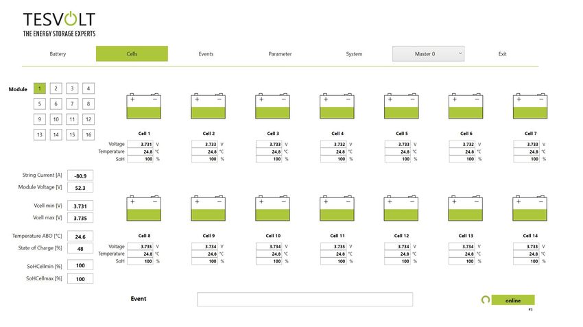
Contents 3

            8.2     Commissioning TS 48 V systems using the master/slave principle. . . . . . . . . . . . . . . . . . . . . . . . . .  44
            9       Decommissioning. . . . . . . . . . . . . . . . . . . . . . . . . . . . . . . . . . . . . . . . . . . . . . . . . . . . . . . . . . . . . . . 46
            10      Expanding the storage system. . . . . . . . . . . . . . . . . . . . . . . . . . . . . . . . . . . . . . . . . . . . . . . . . . . . 47
            10.1 Expanding the capacity using the TESVOLT expansion module. . . . . . . . . . . . . . . . . . . . . . . . . . . . .  47
            10.2 Expanding capacity using additional TS 48 V units. . . . . . . . . . . . . . . . . . . . . . . . . . . . . . . . . . . . . . . .  48
            10.3 Capacity upgrade with SMA Sunny Island . . . . . . . . . . . . . . . . . . . . . . . . . . . . . . . . . . . . . . . . . . . . . . .  51
            11      TESVOLT BATTERY MONITORING SOFTWARE – BatMon. . . . . . . . . . . . . . . . . . . . . . . . . . . . . . . 52
            11.1 Views and functions. . . . . . . . . . . . . . . . . . . . . . . . . . . . . . . . . . . . . . . . . . . . . . . . . . . . . . . . . . . . . . . . . .  52
            11.2 Menu structure . . . . . . . . . . . . . . . . . . . . . . . . . . . . . . . . . . . . . . . . . . . . . . . . . . . . . . . . . . . . . . . . . . . . . .  54
            11.3 The most important cell parameters. . . . . . . . . . . . . . . . . . . . . . . . . . . . . . . . . . . . . . . . . . . . . . . . . . . .  54
            12      Firmware update. . . . . . . . . . . . . . . . . . . . . . . . . . . . . . . . . . . . . . . . . . . . . . . . . . . . . . . . . . . . . . . 55
            13      Fault and warning messages on the TESVOLT TS 48 V. . . . . . . . . . . . . . . . . . . . . . . . . . . . . . . . . 57
            14      Maintenance. . . . . . . . . . . . . . . . . . . . . . . . . . . . . . . . . . . . . . . . . . . . . . . . . . . . . . . . . . . . . . . . . . . 58
            15      Disposal. . . . . . . . . . . . . . . . . . . . . . . . . . . . . . . . . . . . . . . . . . . . . . . . . . . . . . . . . . . . . . . . . . . . . . 59
            16      Legal notice. . . . . . . . . . . . . . . . . . . . . . . . . . . . . . . . . . . . . . . . . . . . . . . . . . . . . . . . . . . . . . . . . . . 60

© TESVOLT We reserve the right to make technical changes. Version RD.TI.015.E.ENG_Installation_Manual_TS48V_v.D.01 Last revised 01/2021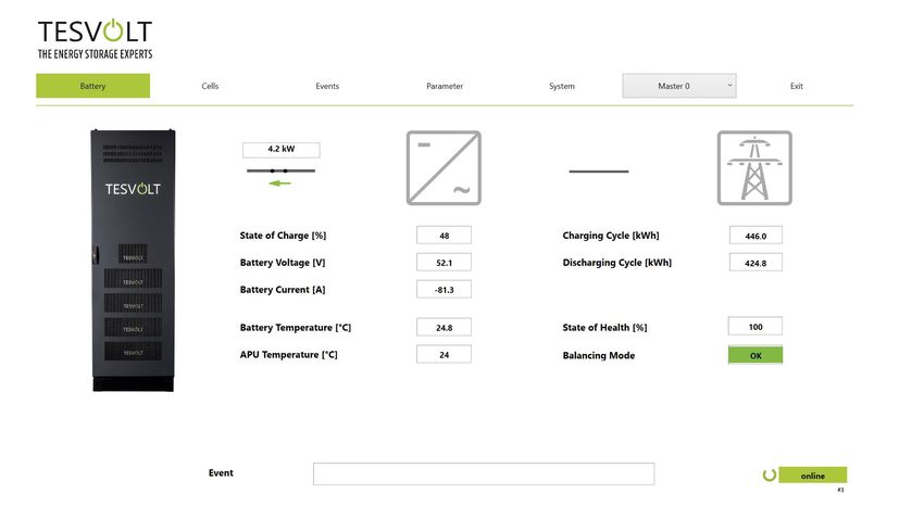
4 Contents

© TESVOLT We reserve the right to make technical changes. Version RD.TI.015.E.ENG_Installation_Manual_TS48V_v.D.01 Last revised 01/2021

IMPORTANT information about this manual 5

        1 IMPORTANT INFORMATION ABOUT THIS MANUAL
        1.1 APPLICABILITY
            This document applies to the modular battery storage system TESVOLT TS 48 V in conjunction with the
            Sunny Island battery inverter manufactured by SMA.
            Read this manual thoroughly to ensure error-free installation, initial commissioning and maintenance
            of the TESVOLT TS 48 V. Installation, initial commissioning and maintenance must be carried out by a
            qualified, authorised specialist. The Installation and Operating Manual should be kept close to the unit
            and must be accessible to all individuals involved in installation or maintenance at all times.
            All information on the battery inverter SMA Sunny Island contained in this manual is non-binding.
            TESVOLT assumes no responsibility for the accuracy and currency of this information. Ensure that you
            follow the relevant product documentation, such as installation or operating manuals from the manu-
            facturers, for the battery inverter and other third-party products.
            This Installation and Operating Manual applies to Germany only, without restriction. Ensure that you
            adhere to the applicable local legal regulations and standards. The standards and legal regulations in
            other countries may contradict the specifications in this manual. In this case, please contact
            service@tesvolt.com or the TESVOLT Service Line +49 (0) 3491 8797 - 200.

       1.2 MEANING OF SYMBOLS
            Symbols in the manual
            This manual contains the following types of warnings and information:
            DANGER!
            This symbol indicates that electric shock may result if you fail to follow the instruction, even when the
            unit is disconnected from the utility grid, as a voltage-free state only occurs after a time delay.
            DANGER!
            This symbol indicates that death or serious injury may result if you fail to follow the instruction.
            CAUTION!
            This symbol indicates that injury may result if you fail to follow the instruction.
            WARNING!
  STOP
            This symbol indicates that damage may result if you fail to follow the instruction.
            NOTE:
            This symbol indicates information relating to use of the device.

            Symbols on the unit
            The following types of warning, prohibition and mandatory symbols are also used on the unit:
            CAUTION! RISK OF CHEMICAL BURNS
            If the battery is damaged and a fault occurs, this may result in electrolyte escaping and the formation
            of hydrofluoric acid in small concentrations and quantities, among other effects. Contact with these liq-
            uids can cause chemical burns.
            • Do not subject the battery modules to violent impact.
            • Do not open, disassemble or mechanically alter the battery modules.
            • If there is contact with the electrolyte, rinse the affected area immediately with water and promptly
              seek medical attention.

© TESVOLT We reserve the right to make technical changes. Version RD.TI.015.E.ENG_Installation_Manual_TS48V_v.D.01 Last revised 01/2021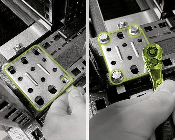
6 IMPORTANT information about this manual

               CAUTION – RISK OF EXPLOSION!
               Improper handling or fire can cause lithium battery cells to ignite or explode and cause serious inju-
               ries.
               • Do not install or operate the battery modules in potentially explosive areas or areas with high
                 humidity.
               • Store the battery modules in a dry place and within the temperature ranges specified in the data
                 sheet.
               • Do not open, drill through or drop the battery cells or modules.
               • Do not expose the battery cells or modules to high temperatures.
               • Do not throw the battery cells or modules into a fire.
               • In case of fire, use CO2 fire extinguishers if the fire comes from the battery. In case of fire in the
                 vicinity of the battery, use an ABC fire extinguisher.
               • Do not use defective or damaged battery modules.
               CAUTION! HOT SURFACE
               If there is a malfunction, components can become very hot and cause serious injury if touched.
               • Switch the battery storage system off immediately if it is defective.
               • Take particular care when handling the unit if malfunctions or defects become apparent.
               NO NAKED FLAMES!
               Handling naked flames and sources of ignition in the immediate vicinity of the storage system is pro-
               hibited.
               DO NOT INSERT ANY OBJECTS INTO THE STORAGE SYSTEM CASING’S OPENINGS!
               No objects, such as screwdrivers, may be inserted through openings in the casing of the storage sys-
               tem.
               WEAR SAFETY GOGGLES!
               Wear safety goggles when working on the unit.
               FOLLOW THE MANUAL!
               It is imperative that you follow the Installation and Operating Manual when working on and operating
               the unit.

          1.3 GENERAL SAFETY INFORMATION
               Danger! Danger of death if the safety information is not followed!
               Improper use can lead to fatal injuries. Any person tasked with working on the system must have read
               and understood this manual, particularly section “2 Safety” on page 8 et seq. All safety information
               must be followed without fail.
               Everyone who works on the TESVOLT TS 48 V must follow the specifications in this manual.
               This manual cannot describe every conceivable situation, and for this reason the applicable standards
               and corresponding occupational health and safety regulations always take priority.
               In addition, installation may also involve residual hazards under the following circumstances:
               • Installation is not carried out properly.
               • Installation is carried out by personnel who have not received the relevant training or instruction.
               • The safety information in this manual is not followed.

© TESVOLT We reserve the right to make technical changes. Version RD.TI.015.E.ENG_Installation_Manual_TS48V_v.D.01 Last revised 01/2021
IMPORTANT information about this manual 7

       1.4 LIMITATION OF LIABILITY
            TESVOLT GmbH assumes no liability for personal injury, damage to property, damage to the product
            and follow-on damage attributable to the following causes:
            • Non-compliance with this manual,
            • Improper use of the product,
            • Repairs, opening the battery cabinet and other actions performed on or with the product by
              unauthorised and/or unqualified personnel,
            • Use of non-approved spare parts.
            Unauthorised modifications or technical changes to the product are forbidden.

       1.5 APPROPRIATE USE
            TESVOLT TS 48 V is a modular battery storage system based on lithium-ion technology. The compo-
            nents were built in accordance with the current state of the art in technology and product-specific
            standards.
            The TESVOLT TS 48 V is intended for use with the SMA Sunny Island battery inverter. Any other use
            must be agreed with the manufacturer and, if necessary, with the local energy supply company.
            It may only be operated in closed rooms. The TESVOLT TS 48 V works in an ambient temperature
            range of -10°C to 50°C and at a maximum humidity of 85%. The battery cabinet may not be exposed to
            direct sunlight or placed directly beside sources of heat.
            The battery cabinet may not be exposed to corrosive environments.
            When installing the battery storage system, ensure that it is standing on a sufficiently dry, horizontal
            and flat surface with sufficient load-bearing capacity.
            The altitude of the installation site may not be higher than 2 ,000 m above sea level without approval in
            writing from the manufacturer.
            In regions subject to flooding, care must be taken to ensure that the battery cabinet is installed in a
            suitably elevated location and is protected against contact with water.
            According to IEC 62619, the battery storage system must be installed in a fire-proofed room. This room
            must be free from fire loads and must be equipped with an independent fire alarm unit in accordance
            with the locally applicable regulations and standards. The room must be separated by class T60 fire
            doors. Comparable fire protection requirements also apply to other openings in the room (e.g. win-
            dows).
            Adherence to the specifications in this manual also forms part of appropriate use.
            The TESVOLT TS 48 V may not be used:
            • for mobile use on land or in the air (it may only be used on water in agreement with, and with the
              written consent of, the manufacturer),
            • for operating medical equipment,
            • as a UPS system.

       1.6 GUARANTEE
            The current guarantee conditions can be downloaded from the internet by visiting www.tesvolt.com.

© TESVOLT We reserve the right to make technical changes. Version RD.TI.015.E.ENG_Installation_Manual_TS48V_v.D.01 Last revised 01/2021
8 Safety

           1.7 PREREQUISITES FOR INSTALLATION TECHNICIANS
               The locally applicable regulations and standards are to be adhered to for all work.
               The installation of the battery storage system may only be carried out by qualified electricians who
               have the following qualifications:
               • Training in dealing with hazards and risks associated with installing and operating electrical equip-
                 ment, systems and batteries,
               • Training in installing and commissioning of electrical equipment,
               • Knowledge of and adherence with the locally applicable technical connection requirements, stan-
                 dards, directives, regulations and laws,
               • Knowledge of handling lithium-ion batteries (transport, storage, disposal, sources of danger),
               • Knowledge of and compliance with this Installation and Operating Manual and other applicable docu-
                 ments,
               • Successful participation in TESVOLT TS 48 V certification training (information about the training
                 courses can be found at www.tesvolt.com. For further information, please send an email to
                 academy@tesvolt.com).

           2 SAFETY
               DANGER! Life-threatening electric shock from damaged components or short circuit
               Bridging the battery poles causes a short circuit that results in a flow of electrical current. A short cir-
               cuit of this type should be avoided under all circumstances. For this reason, please follow these
               instructions:
               • Use insulated tools and insulated gloves.
               • Do not place any tools or metal components on the battery modules or the APU LV.
               • Always remove watches, rings and other metal objects when working with the batteries.
               • Do not install or operate the battery storage system in explosive areas or areas with high humidity.
               • When working on the battery storage system, switch off all voltage supplies first to the charge con-
                 troller, then to the battery, and ensure that they cannot be switched on again.

               DANGER! Chemical burns and poisoning due to electrolyte or poisonous gases
               During normal operation, no electrolyte can escape from the battery and no poisonous gases can
               form. Despite careful design, damage to the battery in the event of a fault can result in escaping elec-
               trolyte or small concentrations and quantities of toxic gases, organic solvent gases and hydrofluoric
               acid: For this reason, please follow these instructions:
               • Do not subject the battery modules to violent impact.
               • Do not open, disassemble or mechanically alter the battery modules.

               In the event of contact with the electrolyte, rinse the affected area immediately with water and
               promptly seek medical advice.

© TESVOLT We reserve the right to make technical changes. Version RD.TI.015.E.ENG_Installation_Manual_TS48V_v.D.01 Last revised 01/2021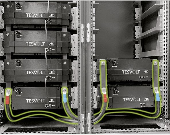
Safety 9

                DANGER! Improper handling can result in life-threatening burns
                Lithium battery cells can ignite if handled improperly. For this reason, ensure that you adhere to the
                following instructions for handing lithium battery cells:
                • Do not install or operate the battery modules in potentially explosive areas or areas with high
                  humidity.
                • Store the battery modules in a dry area and within the temperature ranges specified in the data
                  sheet.
                • Do not open, drill through or drop the battery cells or modules.
                • Do not expose the battery cells or modules to high temperatures.
                • Do not throw the battery cells or modules into a fire.
                • In case of fire, use CO2 fire extinguishers if the fire comes from the battery. In case of fire in the
                  vicinity of the battery, use an ABC fire extinguisher.
                • Do not use defective or damaged battery modules.

                DANGER! Danger of death due to misuse
                Any use that extends beyond or deviates from appropriate use of the battery storage system can lead
                to significant hazards.

                DANGER! Danger of death due to unqualified operators
                Incorrect handling of the battery storage system can result in significant hazards for the operator. For
                this reason, any action that requires the battery cabinet to be opened may only be carried out by quali-
                fied specialists in accordance with the instructions in section “1.7 Prerequisites for installation technici-
                ans” on page 8.

       STOP     WARNING! Improper use can cause damage to the battery cells
                • Do not expose battery cells or modules to rain and do not immerse them in liquids.
                • Do not expose battery cells to corrosive environments (e.g. ammonia, salt).
                • Only use inverters agreed with and approved by TESVOLT.
                • Commission TS 48 V storage systems within six months of delivery at the latest.

© TESVOLT We reserve the right to make technical changes. Version RD.TI.015.E.ENG_Installation_Manual_TS48V_v.D.01 Last revised 01/2021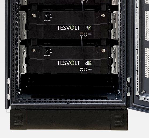
10 Preparation

           3 PREPARATION
          3.1 TOOLS REQUIRED
                TOOLS                                                         USE
                5 – 30 Nm torque wrench with 10 and 13 mm sockets and         e.g. for tightening the grounding connections and the DC con-
                6 mm hexagon socket                                           nections to the battery modules or the DC connecting cables
                                                                              on the SMA Sunny Island
                5 mm hex key                                                  tightening the fastening screws on the cover of the
                                                                              SMA Sunny Island
                TX 25, TX 30 Torx screwdriver                                 e.g. for fastening baying connectors in double cabinets
                PH 3 Phillips screwdriver                                     fastening the battery modules and APU LV in the battery
                                                                              cabinet
                50 mm² and 120 mm² crimping tool                              crimping the ring cable lug, for example for the DC connecting
                                                                              cable on the SMA Sunny Island or bat fuse
                Voltmeter > 400 V AC and > 150 V DC                           measuring the power supply and battery voltages and testing
                                                                              the battery modules’ state of charge
                19 mm spanner                                                 optional: lifting the cabinet cover, fitting the spacers
                Side cutters and combination pliers                           working with the DC connection plastic cover plates on the
                                                                              battery modules

          3.2 TRANSPORT TO THE END CUSTOMER
               Transport regulations and safety information
               All the requirements set out in the German Ordinance on the Transport of Dangerous Goods by Road,
               Rail and Inland Waterways (GGVSEB) and the European Agreement Concerning the International Car-
               riage of Dangerous Goods by Road (ADR) must be adhered to.
               • The TS 48 V may only be transported by the manufacturer or by a forwarding agency engaged by
                 the manufacturer. Should transport on public roads nevertheless be necessary, this may only be
                 carried out by personnel who have received appropriate training and instruction. This instruction is
                 to be documented and carried out periodically.
               • Smoking is prohibited in the vehicle during the transport journey, and also in the immediate vicinity
                 during loading and unloading.
               • Two tested Class D metal fire extinguishers (minimum capacity: 2 kg) and equipment for dangerous
                 goods in accordance with the ADR are to be carried in the vehicle.
               • The freight carrier is prohibited from opening the outer packaging of the battery module.

               DANGER! Risk of injury due to improper transport in a vehicle
               Improper transport and/or inadequate transport locks can cause the load to slide or topple over, lead-
               ing to injuries. Position the cabinet vertically and in such a way that it cannot slide around in the vehi-
               cle, and use securing straps to prevent it from toppling over and sliding.

               CAUTION! Risk of injury due to the battery cabinet toppling over
               The cabinet usually weighs over 100 kg and may topple over if tilted, causing injuries or material dam-
               age.

               CAUTION! Risk of injury if safety shoes are not worn when the cabinet is being transported
               If hazards occur, injuries such as crushing injuries can occur due to the heavy dead weight of compo-
               nents when the cabinet or battery modules is/are being transported. For this reason, all individuals
               involved must wear safety shoes with protective toe caps.

© TESVOLT We reserve the right to make technical changes. Version RD.TI.015.E.ENG_Installation_Manual_TS48V_v.D.01 Last revised 01/2021
Preparation 11
CAUTION!
Please also follow the safety information in section “3.3 Transport at the end customer’s site” on page
11 below, especially when loading and unloading.
WARNING! Risk of damage to the unit during transport with installed battery modules
STOP
Transporting the cabinet with battery modules installed causes damage to the unit. The battery mod-
ules and cabinet must therefore always be transported separately from one another. Never move a
cabinet once fitted with modules or, in particular, suspend it using a lifting device.
WARNING! Risk of damage to the battery modules if transported incorrectly
STOP
No more than five battery modules may be stacked on top of each other during transport, as they may
incur damage due to their high dead weight.
3.3 TRANSPORT AT THE END CUSTOMER’S SITE
CAUTION! Risk of injury due to improper transport of the battery modules
Battery modules are heavy (36 kg) and can cause injuries if they topple over or slide around. Ensure that
transport is carried out safely and that only suitable means of transport are used.
CAUTION! Risk of injury due to the battery cabinet toppling over during transport
The cabinet usually weighs over 100 kg and may topple over if tilted, causing injuries or material dam-
age.
CAUTION! Risk of injury if safety shoes are not worn when the cabinet is being transported
If hazards occur, injuries such as crushing injuries can occur due to the heavy dead weight of compo-
nents when the cabinet or battery modules are being transported. For this reason, all individuals
involved must wear safety shoes with protective toe caps.
CAUTION! Risk of injury from sharp edges and metal panels when transporting the cabinet
When the unpacked cabinet is being transported or installed, there is an increased risk of injury, par-
ticularly due to sharp-edged metal panels. For this reason, all individuals involved must wear safety
gloves.
STOP WARNING! Risk of damage to the unit during transport with installed battery modules
Transporting the cabinet with battery modules installed causes damage to the unit. The battery mod-
ules and cabinet must therefore always be transported separately from one another. Never move a
cabinet once it is fitted with modules or, in particular, suspend it using a lifting device.
NOTE: Transport by at least two people
We recommend using a hand truck. Caution: Do not damage the housing and mounting components!
© TESVOLT We reserve the right to make technical changes. Version RD.TI.015.E.ENG_Installation_Manual_TS48V_v.D.01 Last revised 01/202112 PRePARAtIon
The individual components of the TS 48 V can weigh over 100 kg, which makes them unsuitable for
transport by one person. We recommend at least two people install the system. A dolly or hand truck
is helpful during the installation process. No more than five battery modules may be stored or trans-
ported one on top of the other.
Figure 3.1 Permissible and impermissible storage positions of a packaged battery module
INSTALLATION SITE
Necessary prerequisites
Section “1.5 Appropriate use” on page 7 lists all the necessary prerequisites and conditions for
installing a TS 48 V.
When selecting the installation site, bear in mind transport routes and the necessary site clearance.
WARNING! Possible damage to the building due to excessive static loads.
STOP
Once installed, the battery storage system usually weighs from several hundred kilograms to signifi-
cantly more than 1,000 kilograms. Ensure that the installation site has sufficient load-bearing capacity.
If in doubt, consult a structural engineer.
Dimensions
≥15
60
Tilt height = A
60
Cabinet height = B
Type A B
≥65
≥190
TS 25 ≥145 130
A
B
TS 40 ≥205 190
TS 50 ≥245 230
≥65
≥70
All dimensions in cm. Space required Additional space required
(incl. installation) for servicing, etc.
© TESVOLT We reserve the right to make technical changes. Version RD.TI.015.E.ENG_Installation_Manual_TS48V_v.D.01 Last revised 01/2021Technical data 13
4 TECHNICAL DATA
4.1 TESVOLT TS 48 V
TESVOLT BATTERY MODULE
Energy module 4.8 kWh
C-rate 1C
Cell Lithium NMC prismatic (Samsung SDI)
Max. charging/discharging current 94 A
Cell balancing Active Battery Optimizer
Cycles expected at 100% DoD | 70% EoL | 23°C +/- 5°C 1C/1C 6,000
Cycles expected at 100% DoD | 70% EoL | 23°C +/- 5°C 0.5C/0.5C 8,000
Efficiency (battery) up to 98 %
Operating voltage 47.6 to 58.1 V DC
Operating temperature -10 to 50 °C
Humidity 0 to 85 % (non-condensing)
Altitude of installation site < 2,000 m above sea level
Weight 36 kg
Dimensions (H x W x D) 163 x 490 x 480 mm
Certificates/standards Cell IEC 62619, UL 1642, UN 38.3
Product CE, UN 38.3, IEC 6100061/2/3/4, BattG 2006/66/EC
Guarantee 10-year performance guarantee, 5-year system guarantee
Recycling TESVOLT provides a free battery collection scheme in Germany
Battery specification as per DIN EN 62620:2015 IMP47/175/127/[14S]E/20+60/90
COMPLETE SYSTEM
Number of battery modules 2 3 4 5 6 7 8 9 10
TS 25 (2 – 5 modules) 1,300 x 600 x 600 mm (H x W x D) • • • •
TS 40 (2 – 8 modules) 1,900 x 600 x 600 mm (H x W x D) • • • • • • •
TS 50 (2 – 10 modules) 2,300 x 600 x 600 mm (H x W x D) • • • • • • • • •
TS Flex (energy as required) Flexibly configure your system according to your requirements.
Energy [kWh] 9.6 14.4 19.2 24.0 28.8 33.6 38.4 43.2 48.0
Capacity [Ah] 188 282 376 470 564 658 752 846 940
Maximum output power 1C
Self-consumption (standby) 3 W (without battery inverter)
Weight [kg] 192 228 264 300 386 422 458 514 550
System single-phase, three-phase
Protection class IP 20 (indoor use)
© TESVOLT We reserve the right to make technical changes. Version RD.TI.015.E.ENG_Installation_Manual_TS48V_v.D.01 Last revised 01/202114 ts 48 V bAtteRy stoRAge systeM
5 TS 48 V BATTERY STORAGE SYSTEM
5.1 CABINET STRUCTURE AND COMPONENTS
A B C C.1
B
I
C-rail (TS) Base corner cover plate
D D.1 E E.1
Pan head screw with washer Cage nut (left) and auxiliary
tool for fitting
F G
Cable retention clip Ring screw
H H.1 I I.2
I.3
Empty VX cabinet H.2 H.3
I.1 I.4
A Spacer with accessories for Grounding point with fitting
lifting the top of the cabinet accessories
J K K.1 K.2
J.1
J.2
J.3
Grounding strip (door) TS cabinet extension set
with accessories
L L.1 L.2 L.3 M M.1 M.3
M.4
M.2
VX cabinet extension set
M.5
N N.2 TS/VX cabinet extension set
N.3
N.1
N.4
N.5
N.6
Empty TS cabinet Grounding set for cabinet
extension
© TESVOLT We reserve the right to make technical changes. Version RD.TI.015.E.ENG_Installation_Manual_TS48V_v.D.01 Last revised 01/2021TS 48 V battery storage system 15
5.2 CABINET SCOPE OF DELIVERY
ITEM QUANTITY* DESCRIPTION
TS 25 TS 40 TS 50
A 1 1 1 Cabinet
B 1 1 1 C-rail (VX cabinet – pre-installed)
C 2 2 2 Base corner cover plate (right)
C.1 2 2 2 L Base corner cover plate (left)
D 50 50 50 M6 x 16 pan head screw (Phillips)
D.1 50 50 50 Plastic washer
E 50 50 50 M6 cage nut
E.1 1 1 1 L Auxiliary tool for fitting the cage nuts
F 2 2 2 Cable retention clip for C-rail (strain relief)
G 4 4 4 Ring screw
H 4 4 4 20 mm spacer
H.1 4 4 4 L M6 x 16 countersunk screw (Torx TX 30)
H.2 4 4 4 L Cover cap
H.3 4 4 4 L Plastic washer
I 1 1 1 Grounding point (VX cabinet – two pre-installed grounding points)
I.1 2 2 2 L ST5 x 12 self-tapping screw (Torx TX 30)
I.2 1 1 1 L M8 nut
I.3 1 1 1 L Washer
I.4 1 1 1 L Contact washer
J 1 1 1 10 mm² grounding strip (M8 ring cable lugs on both ends, pre-installed on VX cabinet)
J.1 2 2 2 L M8 nut
J.2 2 2 2 L Washer
J.3 2 2 2 L Contact washer
K 1 TS cabinet extension set
K.1 6 L Baying connector
K.2 24 L ST5.5 x 13 mm pan head screw (Torx TX 30)
L 1 VX cabinet extension set
L.1 8 L Baying connector
L.2 24 L ST5.5 x 13 mm pan head screw (Torx TX 30)
L.3 12 L M6 x 35 setscrew
M 1 TS/VX cabinet extension set
M.1 8 L Baying connectors
M.2 32 L ST5.5 x 13 mm pan head screw (Torx TX 30)
M.3 20 L M8 x 16 mm screw
M.4 20 L M8 speed nut
M.5 1 L 6.00 m sealing strip (use is optional)
N 1 Cabinet extension grounding set
N.1 2 L M8 x 30 screw
N.2 2 L Spring washer
N.3 2 L Washer
N.4 2 L Contact washer
N.5 2 L M8 speed nut
N.6 1 L Grounding cable
*The quantities given are for the standard configurations of the storage unit models. The quantities provided here will vary accordingly in non-
standard configurations.
© TESVOLT We reserve the right to make technical changes. Version RD.TI.015.E.ENG_Installation_Manual_TS48V_v.D.01 Last revised 01/202116 ts 48 V bAtteRy stoRAge systeM
5.3 CONSTRUCTION AND STORAGE SYSTEM COMPONENTS
1
5.1 5.2
1 3.5
3.1 3.2
APU LV
2 3.3 3.4
2
4.1
4.2
4.4
4.8-1C-LV48 battery module 4.3
3 3.1
3.2
3.3
3.4 Empty VX cabinet
3.5 3.6
APU LV connector kit
4 4.1 3.6
4.2
4.3
C.1 C
4.4
LV module connector kit Installed TS 48 V
5 5.2 6 7 8
5.1
5.3
5.5 5.7
5.6 Type plate TS 48 V Installation manual TESVOLT USB-Stick
5.4
LV DC connecting cable set 14
9
BATTERIERAUM
BATTERY ROOM
Battery room sticker
© TESVOLT We reserve the right to make technical changes. Version RD.TI.015.E.ENG_Installation_Manual_TS48V_v.D.01 Last revised 01/2021TS 48 V battery storage system 17
5.4 SCOPE OF DELIVERY FOR STORAGE SYSTEM COMPONENTS
ITEM QUANTITY* DESCRIPTION
TS 25 TS 40 TS 50
1 1 1 1 APU LV
2 5 8 10 Battery Battery module 4.8-1C-LV48 incl. Active Battery Optimizer (ABO)
3 1 1 1 APU LV connector kit from the APU to the first battery module
3.1 1 1 1 L LV S-shaped connector
3.2 1 1 1 L Short LV I-shaped connector
3.3 1 1 1 L Rack balancing bridge
3.4 1 1 1 L CAT 6 patch cable – 0.27 m ribbon
3.5 4 4 4 L DIN 6923 - M8 self-locking flanged nut
3.6 2 2 2 L DIN 6921 - M8 x 16 hexagon flanged bolt
4 4 7 9 LV module connector kit
4.1 8 14 18 L Long LV I-shaped connector
4.2 8 14 18 L DIN 6921 - M8 x 20 hexagon flanged bolt
4.3 4 7 9 L CAT 6 patch cable – 0.27 m ribbon
4.4 4 7 9 L Rack balancing bridge
5 1 1 1 LV DC connecting cable set
5.1 1 1 1 L DC connecting cable – 5.00 m 120 mm2 (+, with red marking on one end, M8 ring cable lug)
5.2 1 1 1 L DC connecting cable – 5.00 m 120 mm2 (-, with blue marking on one end, M8 ring cable lug)
5.3 1 1 1 L CAT 6 patch cable – 5.00 m
5.4 1 1 1 L Grounding cable – 5.00 m 16 mm2 (M8 ring cable lug on one end)
5.5 1 1 1 L Red heat shrink tubing – 65 mm for 120 mm²
5.6 1 1 1 L Blue heat shrink tubing – 65 mm for 120 mm²
5.7 2 2 2 L M8 ring cable lug for 120 mm²
6 2 2 2 Type plate TS 48 V
7 1 1 1 TESVOLT TS 48 V Installation and Operating Manual
8 1 1 1 TESVOLT USB-Stick
9 1 1 1 Battery room sticker
*The quantities given are for the standard configurations of the storage unit models. The quantities provided here will vary accordingly in non-
standard configurations.
© TESVOLT We reserve the right to make technical changes. Version RD.TI.015.E.ENG_Installation_Manual_TS48V_v.D.01 Last revised 01/202118 ts 48 V bAtteRy stoRAge systeM
5.5 OTHER COMPONENTS
10 11 12 13
Switch SMA Sunny Island SMA Sunny Home SMA Data Manager M incl.
Manager 2.0 external 24 V power supply
14 15 15.1 16 16.1 17 17.2
17.1
17.3
17.4 17.5
SMA Energy Meter 2.0 LV B01 2X bat fuse and LV B03 4X bat fuse and DC connector set bat fuse to
NH1 250 A tag fuse NH1 250 A tag fuse Sunny Island (10 m)
18 18.2 19 20
18.1
18.3
18.4
Cabinet connector kit Emergency power Emergency power
1.20 m or 2.30 m distribution, single-phase distribution, three-phase
© TESVOLT We reserve the right to make technical changes. Version RD.TI.015.E.ENG_Installation_Manual_TS48V_v.D.01 Last revised 01/2021TS 48 V battery storage system 19
5.6 SCOPE OF DELIVERY FOR OTHER COMPONENTS
ITEM QUANTITY DESCRIPTION
10 1 Switch
11 1 or 3 SMA Sunny Island 4.4 M/6.0 H/8.0 H
12 1 SMA Sunny Home Manager 2.0
13 1 SMA Data Manager M alternative for item 12; incl. external 24 V power supply
14 1 SMA Energy Meter 2.0 alternative for item 12
15 Optional: LV B01 2X bat fuse
15.1 3 L NH1 250 A tag fuse
16 Optional: LV B03 4X bat fuse
16.1 6 L NH1 250 A tag fuse
17 Optional: DC connector set bat fuse to Sunny Island (10 m)
17.1 1 L DC connecting cable – 10.00 m 50 mm²
17.2 6 L 50 mm² M8 ring cable lug
17.3 6 L 50 mm² M10 ring cable lug
17.4 6 L Thin-wall heat shrink tubing, 40 mm, red
17.5 6 L Thin-wall heat shrink tubing, 40 mm, blue
18 Optional: Cabinet connector kit – 1.20 m or 2.30 m
18.1 1 L DC connecting cable – 1.20 m or 2.30 m 120 mm² (+, M8 ring cable lugs, with red marking on both ends)
18.2 1 L DC connecting cable – 1.20 m or 2.30 m 120 mm² (-, M8 ring cable lugs with blue marking on both ends)
18.3 1 L CAT 6 patch cable - 2.00 m or 3.00 m)
18.4 2 L DIN 6921 - M8 x 20 hexagon flanged bolt
19 Optional: Emergency power distribution, single-phase
20 Optional: Emergency power distribution, three-phase
© TESVOLT We reserve the right to make technical changes. Version RD.TI.015.E.ENG_Installation_Manual_TS48V_v.D.01 Last revised 01/202120 ts 48 V bAtteRy stoRAge systeM
5.7 CONNECTIONS AND STRUCTURE OF THE APU LV
15 16
CHARGER BATTERY
14
13
1 2 4 5 7 9 10 11 12
3 6 8
NO. DESIGNATION DESCRIPTION
1 CHARGER + DC connection on the SMA Sunny Island or bat fuse for the positive pole (red)
2 CHARGER − DC connection on the SMA Sunny Island or bat fuse for the negative pole (blue)
3 E-STOP Two-pin plug for optional connection of a floating emergency stop switch for quick shutdown
(pre-installed with the bridge on delivery)
4 TERM CAN bus termination
TERM must be activated (ON) for the first and last CAN bus participant.
5 CAN IN APU LV master-slave communication (input)
6 CAN OUT APU LV master-slave communication (output)
7 CAN SMA ComSync IN connection on the SMA Sunny Island
8 LAN Ethernet interface for access to APU LV using BatMon (DHCP router required)
9 ADDRESS Further information can be found in the section “Overview of all addressing options” on page 51.
10 BAT-COM Communication port to the first battery module
11 BATTERY − The battery’s DC connection for the negative pole
12 BATTERY + The battery’s DC connection for the positive pole
13 DISPLAY Display interface
14 MARKING Marking for activating and changing the display by tapping
15 SWITCH On/off switch for the battery
16 Fuse (F1) Fuse to protect the APU LV
(2 A miniature fuse, 5 x 20 mm, time lag (T) according to DIN 41571-2, type: ESKA 521.020,
250 VAC). Operation is not possible with a defective fuse.
5.8 CONNECTIONS AND STRUCTURE OF THE BATTERY MODULE
NO. DESIGNATION DESCRIPTION
17 − POLE Battery negative pole
19 18 + POLE Battery positive pole
20 19 RACK BALANCING IN Rack balancing (input)
17 18
20 RACK BALANCING OUT Rack balancing (output)
21 22 21 BAT-COM OUT Battery module communica-
tion port (output)
22 BAT-COM IN Battery module communica-
tion port (input)
© TESVOLT We reserve the right to make technical changes. Version RD.TI.015.E.ENG_Installation_Manual_TS48V_v.D.01 Last revised 01/2021TS 48 V battery storage system 21
5.9 WIRING THE BATTERY MODULES
TS 25 wiring
1
2
3
4
5
DC module connector Rack balancing BAT-COM 1 Order in the battery string
© TESVOLT We reserve the right to make technical changes. Version RD.TI.015.E.ENG_Installation_Manual_TS48V_v.D.01 Last revised 01/202122 TS 48 V battery storage system
TS 40 wiring
1
2
3
4
5
6
7
8
DC module connector Rack balancing BAT-COM 1 Order in the battery string
© TESVOLT We reserve the right to make technical changes. Version RD.TI.015.E.ENG_Installation_Manual_TS48V_v.D.01 Last revised 01/2021TS 48 V battery storage system 23
TS 50 wiring
1
2
3
4
5
6
7
8
9
10
DC module connector Rack balancing BAT-COM 1 Order in the battery string
© TESVOLT We reserve the right to make technical changes. Version RD.TI.015.E.ENG_Installation_Manual_TS48V_v.D.01 Last revised 01/202124 TS 48 V battery storage system
2 x TS 40 wiring
1 16
2 15
3 14
4 13
5 12
6 11
7 10
8 9
DC module connector Rack balancing BAT-COM 1 Order in the battery string
© TESVOLT We reserve the right to make technical changes. Version RD.TI.015.E.ENG_Installation_Manual_TS48V_v.D.01 Last revised 01/2021InstAllAtIon 25
6 INSTALLATION
6.1 SETTING UP THE CABINET
1 Remove the packaging and transport locks from the cabinet.
2 Optional: Install the ring screws:
When transporting the empty cabinet by crane, install four ring
screws at the four corners of the cabinet. To do this, remove all
the fastening screws from the cabinet cover and replace them
with the ring screws G .
3 Transport the empty cabinet to its final installation site. While doing so, ensure that you follow the
safety information in the section “3.3 Transport at the end customer’s site” on page 11.
4 Optional: Lifting the cabinet covers for additional ventilation:
First of all, remove all ring screws or fastening screws and the
upper cabinet cover (TS cabinet variant shown in picture as exam-
ple).
5 Optional: Lifting the cabinet covers for additional ventilation:
Now screw the four spacers H into the threaded holes at each
corner of the cabinet frame.
6 Optional: Lifting the cabinet covers for additional ventilation:
Then place the top cabinet cover on the spacers and fasten it with
four M6 x 16 countersunk screws (TX 25) H.1 including plastic
washers H.3 .
Next fasten the cover caps H.2 to the plastic washers.
7 Now attach the type plates 6 to the cabinet in the following positions: 1 x on the inside of the door
and 1 x visible on one external side wall.
© TESVOLT We reserve the right to make technical changes. Version RD.TI.015.E.ENG_Installation_Manual_TS48V_v.D.01 Last revised 01/202126 InstAllAtIon
8 TS cabinet only: Now fit the cage nuts E for fastening the bat-
tery modules 2 using the auxiliary tool E.1 . Distribute the cage
nuts from bottom to top. Start at the bottom edge of the slide rail
for the relevant battery module. Fit the first two cage nuts in the
opening directly above on both sides, leave the next seven open-
ings empty and fit another pair of cage nuts in the next opening in
both rack rails.
9 TS cabinet only: Fit the cage nuts E for fastening the APU LV
1 in the rack rails using the auxiliary tool E.1 . The APU LV
occupies the topmost slide rail in the cabinet. Distribute the cage
nuts from bottom to top. Start at the bottom edge of the slide rail.
Leave the first opening empty, fit the first two cage nuts in the
next opening on both sides, leave the next four openings empty
and fit another pair of cage nuts in the next opening in both rack
rails.
10 VX cabinet only: Now, fit the cage nuts E for fastening the bat-
tery modules 2 with the auxiliary tool E.1 (see “5.9 Wiring the
battery modules” on page 21 for the positions of the battery
modules). Distribute the cage nuts from bottom to top. Start at the
bottom edge of the slide rail for the relevant battery module. Fit
the first two cage nuts in the second opening from the bottom on
both sides, and fit the remaining two cage nuts in the top opening
in the two slide rails.
11 VX cabinet only: Fit the cage nuts E for fastening the APU LV
1 in the slide rails using the auxiliary tool E.1 . The APU LV
uses the top slide rails in the left half of the cabinet. Distribute the
cage nuts from bottom to top. Start at the bottom edge of the slide
rails of the APU LV. Use the first opening and fit the first two cage
nuts on both sides. Now, fit the remaining two cage nuts in the
second opening in both slide rails from the top.
12 TS cabinet only: Fit the grounding point to an appropriate location
on the cabinet’s frame profile (e.g. at the front, on the lower left
cabinet frame profile). The grounding point I is fastened with
two ST5.5 x 12 (TX 30) self-tapping screws L1 .
© TESVOLT We reserve the right to make technical changes. Version RD.TI.015.E.ENG_Installation_Manual_TS48V_v.D.01 Last revised 01/2021InstAllAtIon 27
13 TS cabinet only: Ground the cabinet door with the grounding strip
J . Use the grounding point on the side panel a few centimeters
above the base, roughly at the same height as the lowest door
hinge. First, remove the protective caps from the copper bolts on
this grounding point and the cabinet door. Then connect the two
grounding points using the grounding strip and the M8 nuts J.1
with washer J.2 and contact washer J.3 . The tightening torque
is 10 Nm.
14 TS cabinet only: Install the C-rail B above the APU LV position.
To do this, first, take the auxiliary tool E and install two cage
nuts E.1 in the two rack rails in the fourth hole from the top. Fas-
ten the C-rail to these with two M6 x 16 pan head screws D
(Phillips) and two plastic washers D.1 .
TS 25V only: The APU LV has to be installed first due to the TS 25
cabinet’s small dimensions. The C-rail can then be fitted.
15 Prepare the base for fitting the storage system. A brush strip can
be used in the base of the cabinet for easy cable routing. Simply
install the brush strip on the required side of the base. To relocate
the brush strip, two screws must be removed on the right and left
sides of the brush strip. Then remove the base cover plate on the
relevant side of the cabinet. Swap the brush strip and cover plate
and then refit both.
16 Now you can install the base corner cover plates C / C.1 . The
cover plates are snapped into place on each corner of the cabinet
base. The logo on each base cover plate must face forwards on
the front of the cabinet and to the rear on the back of the cabinet.
6.2 FITTING A CABINET EXTENSION
1 The first step is to remove the side panels on each cabinet where
the cabinets are to be connected together.
© TESVOLT We reserve the right to make technical changes. Version RD.TI.015.E.ENG_Installation_Manual_TS48V_v.D.01 Last revised 01/202128 InstAllAtIon
2 Cabinet extension for TS cabinet only: Temporarily remove the
rear panel from the right-hand cabinet. Now remove the brackets
of the previously dismantled side panels on both halves of the
cabinet. Then refit the rear panel of the right-hand cabinet.
Prepare the extension cabinet according to section “6.1 Setting
up the cabinet” on page 25 et seq.
3 Cabinet extension for TS cabinet only: All six baying connectors
K.1 can now be fitted to connect the two halves of the cabinets.
The baying connectors are located on the vertical cabinet frame
profiles at the bottom, in the middle, and at the top. To do this,
firstly place two ST5.5 x 13 pan head screws K.2 in the diago-
nally converging extended holes with the bent end of the baying
connector at the top. For now, tighten the screws hand-tight only.
4 Cabinet extension for TS cabinet only: Once all the baying con-
nectors have been pre-fitted, take a hammer and carefully tap
down each baying connector in turn. This reduces the distance
between the screws and pulls the two halves of the cabinet
together. Stop when the two ST5.5 x 13 pan head screws K.2 are
at the upper end of the extended holes in the baying connector.
Now fully tighten the two pan head screws.
5 Cabinet extension for TS cabinet only: Fit two further ST5.5 x 13
pan head screws K.2 in the small holes in the baying connector.
6 Cabinet extension for VX cabinet only: Once the side panel has
been removed, take out the cage nuts that held it in place.
© TESVOLT We reserve the right to make technical changes. Version RD.TI.015.E.ENG_Installation_Manual_TS48V_v.D.01 Last revised 01/2021InstAllAtIon 29
7 Cabinet extension for VX cabinet only: First of all, on the front of
the cabinet, attach three baying connectors L.1 to the central,
vertical cabinet profiles inside the cabinet at the top, middle and
bottom. The baying connectors are fastened to the frame profiles
with two M6 x 35 setscrews L.3 on each side from the right and
left. For now, only tighten the screws loosely.
8 Cabinet extension for VX cabinet only: Now, fit the remaining
three baying connectors L.1 to the vertical cabinet profiles at the
rear of the cabinet at the same height as the front baying connec-
tors already installed. When fitting the bottom baying connector,
use the same process as for fitting on the front cabinet profiles.
For the middle and top baying connectors, the slide rail must first
be removed from one side of the fitting area.
9 Cabinet extension for VX cabinet only: Now fasten the middle and
the top baying connectors using their four front holes using four
ST5.5 x 13 pan head screws L.2 . Then refit the relevant slide rail.
10 Cabinet extension for TS/VX cabinet only – optional:
The sealing strip M.5 can be fitted between the cabinet frame
abutting faces. The sealing strip has a self-adhesive side; use this
to fasten it to one of the cabinets’ abutting faces (frame profiles).
The sealing strip is purely aesthetic and does not have a func-
tional purpose.
11 Cabinet extension for TS/VX cabinet only: Now attach the lower
baying connectors M.1 in the cabinet. The lower baying connec-
tor is attached to the two abutting horizontal cabinet frame pro-
files on the two halves of the cabinet. To do this, place a speed nut
M.4 underneath each of the corner holes of the baying connector
from the cabinet frame profile side. Use an M8 x 16 pan head
screw M.3 to fasten the connector.
12 Fit the last upper baying connector M.1 in the center of the cabinet where the abutting cabinet frame
profiles of the two halves of the cabinet meet. Repeat the above step.
© TESVOLT We reserve the right to make technical changes. Version RD.TI.015.E.ENG_Installation_Manual_TS48V_v.D.01 Last revised 01/202130 InstAllAtIon
13 Cabinet extension for TS/VX cabinet only: Now fit the baying
connectors M.1 on the front and rear vertical cabinet frame pro-
files of both halves of the cabinet half-way up the cabinet. To do
this, place an M8 speed nut M.4 underneath each of the corner
holes of the baying connector from the cabinet frame profile side.
Fasten the connector to the VX cabinet side with two M8 x 16
screws M.3 and two ST5.5 x 13 pan head screws on the TS cabi-
net side M.2 using the small holes in the baying connector.
14 Fit the cabinet grounding connection set N to equalise the
potential between the two halves of the cabinet. To do this, insert
the M8 speed nuts N.5 from the side into the two middle cabinet
profiles at the cabinet base. You are free to choose the position,
but both speed nuts must be directly opposite each other.
15 Now prepare the grounding cable N.6 for installation. To do this,
put a spring washer N.2 , a washer N.3 , the grounding cable’s
cable eyelet, N.6 and, finally, the contact washer N.4 onto the
M8 x 30 screw N.1 . Ensure that the teeth of the contact washer
N.4 are pointing downwards, towards the end of the screw.
16 Fit the prepared grounding cable N.6 using the M8 speed nuts
N.5 already installed in the central adjacent cabinet frame pro-
files at the cabinet base. Tighten both M8 pan head screws N.1
with a torque of 12 Nm.
6.3 INSTALLING THE COMPONENTS
CAUTION! Electric shock if grounding is insufficient or absent!
If a fault occurs on the unit, insufficient or absent grounding can cause damage to the unit, and this
brings with it the risk of injury from electric shock.
1 Ensure the battery cabinet is grounded. To do this, connect the grounding cable to the central ground-
ing point I . Use an M8 nut I.2 for this and tighten to a torque of 8 Nm.
NOTE: Before installing the APU LV 1 note its serial number in the document “CS-S.FB.002.E.ENG_
Commissioning_Protocol_TS48V”, which can be found on the TESVOLT USB-Stick 8 . The serial num-
ber can be found on a sticker on the underside of the APU LV. If you do not have a template, please con-
tact service@tesvolt.com or the TESVOLT Service Line +49 (0) 3491 87 97 - 200.
© TESVOLT We reserve the right to make technical changes. Version RD.TI.015.E.ENG_Installation_Manual_TS48V_v.D.01 Last revised 01/2021InstAllAtIon 31
2 Place the APU LV on the top slide rail. At the four fastening points,
use the M6 x 16 pan head screws D (Phillips) and plastic wash-
ers D.1 included in the pack to fasten to the pre-installed cage
nuts.
3 TS 25 (TS cabinet) only: To relieve the strain, fit the C-rail B above the APU LV 1 . Fasten the
C-rail B to the pre-installed cage nuts D.1 using two M6 x 16 pan head screws D (Phillips) and
plastic washers.
4 The two-pin plug for the e-stop connection on the APU LV must be
plugged in for operation. For further information about the e-stop,
please refer to section “6.4 E-stop contact” on page 35 of this
Installation and Operating Manual.
5 All battery modules 2 of a TS 48 V battery storage system must have exactly the same state of
charge. So be sure to check the voltage of the battery modules before fitting them. A battery module’s
correct voltage at installation must be 50.0 +/− 0.1 V. If you notice any deviations from this, please con-
tact service@tesvolt.com or the TESVOLT Service Line +49 (0) 3491 87 97 - 200.
6 For systems with multiple APU LVs only: Divide the modules evenly between all the APU LVs in the
system. All APU LVs must have the same number of connected battery modules.
7 Fit the first battery module below the APU LV in the slide rails.
Fasten it to the pre-installed cage nuts using four M6 x 16 pan
head screws D (Phillips) and plastic washers D.1 .
8 Now fit the remaining modules one after the other from the top to
the bottom and fasten them in place as described above.
© TESVOLT We reserve the right to make technical changes. Version RD.TI.015.E.ENG_Installation_Manual_TS48V_v.D.01 Last revised 01/202132 InstAllAtIon
CAUTION! Risk of injury due to short circuit!
The battery modules and other components of the TS 48 V are already live before commissioning. An
inadvertent short circuit can lead to severe injuries. It is therefore essential that you avoid any action
that may result in a short circuit, particularly when using uninsulated tools.
9 To fit the DC connectors, the side covers on the battery modules
must be removed and prepared.
To remove the cover:
1. loosen the clasp,
2. gently pull the cover forwards from the bottom,
3. rotate the cover towards the side panel.
10 Now prepare the side covers on the battery modules for fitting the
DC connectors:
1. Separate the predetermined breaking point using side cutters,
2. carefully break off the material to be removed using
combination pliers.
At the contact protection point on the last battery module, remove
only the upper section for the module connector. The lower sec-
tion remains closed to provide a touch guard.
11 Now fit the DC connector from the APU LV 1 to the first battery
module 2 . Start with the S-connector 3.1 from the APU LV
connector set 3 . The S-connector connects the BATTERY con-
nection 11 of the APU LV to the negative pole 17 of the first bat-
tery module. Use an M8 self-locking flanged nut 3.5 to fasten to
the APU LV. Initially, tighten the connection so that it is hand-tight
only. The DC connector 4.1 is only fastened to the battery module
as part of the process of connecting to the following battery mod-
ule.
12 Next, fit the short “I” connector 3.2 from the APU LV connector
set 3 . The connector forms a contact between the BATTERY “+”
connection 12 of the APU LV and the positive pole 18 of the first
battery module. Initially, tighten it to the APU LV so that it is hand-
tight only using an M8 self-locking flanged nut 3.5 . The DC con-
nector 4.1 is only fastened to the battery module as part of the
process of connecting to the following battery module.
© TESVOLT We reserve the right to make technical changes. Version RD.TI.015.E.ENG_Installation_Manual_TS48V_v.D.01 Last revised 01/2021InstAllAtIon 33
13 You can now make the DC connections to the next battery module.
To do this, use two long “I” connectors 4.1 from the LV module
connector kit 4 . Two M8 x 20 hexagon flanged bolts 4.2 are
provided in each connector kit for fastening.. The next DC connec-
tor 4.1 is only fastened to the next battery module as part of the
process of connecting to the next battery module below. Initially,
tighten the connections so that they are hand-tight only.
14 Continue using this procedure until you reach the last, lowest
module. The long “I” connectors 4.1 are initially fastened to the
last module so that they are hand-tight only using two M8 x 16
hexagon flanged bolts 3.6 (part of the APU connector kit).
Cabinet extension only: Two M8 x 20 hexagon flanged bolts 4.2
are also used to fasten the long “I” connectors 4.1 and the DC
cabinet connecting cables 18.1 / 18.2 on the bottom module. The
procedure is described in the next step.
DANGER! Incorrect installation of the DC cabinet connecting cables when extending a cabinet can
lead to a short circuit and life-threatening injuries
If the DC connecting cables 18.1 / 18.2 are incorrectly installed, this may result in a short circuit. This
may cause components to become extremely hot or produce an electric arc, which can lead to serious
injuries. Pay careful attention to the following points to avoid a short circuit:
• Install the DC connecting cables 18.1 / 18.2 one after the other and always fasten the first DC con-
necting cable to both battery modules first before proceeding to fit the second DC connecting
cable.
• Ensure the DC connecting cables’ contacts 18.1 / 18.2 do not accidentally touch other components
during the fitting procedure.
• Ensure that wiring is carried out properly in accordance with section “5.9 Wiring the battery mod-
ules” on page 21 et seq.
15 Cabinet extension only: Install all battery modules on the right
side from the bottom upwards. Attach two long LV I-shaped con-
nectors 4.1 between the modules using two M8 x 20 hexagon
flanged bolts 4.2 or M8 x 16 3.6 for the last module. Then install
each of the DC connecting cables 18.1 / 18.2 using two M8 x 20
hexagon flanged bolts 18.4 . Connect the DC connecting cable with
red marking 18.1 to the positive pole and the blue 18.2 to the nega-
tive pole on the lowest module in the left and right halves of the
cabinet. Tighten all the connections so that they are hand-tight.
16 Cabinet extension only: Using the patch cable 18.3 , connect the
BAT-COM OUT connection on the lowest module on the left side to
the BAT-COM IN connection on the lowest module on the right
side. Connect the remaining BAT-COM connections on the rest of
the battery modules. Note the BAT-COM cabling specifications on
the left side of the cabinet in the subsequent installation steps.
© TESVOLT We reserve the right to make technical changes. Version RD.TI.015.E.ENG_Installation_Manual_TS48V_v.D.01 Last revised 01/202134 InstAllAtIon
17 You may now fit the rack balancing bridges 3.3 / 4.4 . Use the
rack balancing bridge 3.3 from the APU connector kit on the first
module below the APU LV. The remaining rack balancing bridges
4.4 can be found in the module connector kit.
WARNING! Possible damage to the unit due to incorrect BAT-COM wiring.
STOP
Incorrect connection of the BAT-COM communication cable leads to malfunctions in battery operation.
Ensure that wiring is carried out properly in accordance with section “5.9 Wiring the battery modules”,
page 21 et seq.
18 Wire the BAT-COM communication cable using the supplied patch
cables 3.4 and 4.3 . Using the patch cable 3.4 , connect the
BAT-COM connections 10 on the APU LV to the BAT-COM “IN” con-
nection on the battery module located beneath the APU LV. You
can then use a patch cable 4.3 to connect the same module’s
BAT-COM “OUT” connection to the next module’s BAT-COM “IN”
connection. Connect the remaining battery modules in the same
way using the patch cables 4.3 . The last battery module’s
BAT-COM “OUT” connection remains unused.
19 Now tighten the self-locking nuts 3.5 on the BATTERY connec-
tions on the APU LV 11 / 12 with a tightening torque of 12 Nm. The
M8 x 20 4.2 and M8 x 16 3.6 hexagonal flanged screws on the DC
connections on the battery modules 17 / 18 can now be tightened
with a tightening torque of 12 Nm.
20 Finally, fit the side covers on the battery modules. Ensure the
brackets snap into place correctly.
21 Now lay the DC cables 5.1 / 5.2 starting from the APU LV to the
SMA Sunny Island or the bat fuse 15 or 16 . Note that the cable
can only be shortened on the SMA Sunny Island or bat fuse side.
To relieve the strain on the DC cables, install the two cable reten-
tion clips F above the CHARGER connections of the APU LV 1 /
2 on the C-rail B .
© TESVOLT We reserve the right to make technical changes. Version RD.TI.015.E.ENG_Installation_Manual_TS48V_v.D.01 Last revised 01/2021You can also read