Project Description - Enviro Knowledge Center
←
→
Page content transcription
If your browser does not render page correctly, please read the page content below
CHAPTER 5

Project Description
ENVIRONMENTAL IMPACT ASSESSMENT FOR PROPOSED CLINICAL WASTE TREATMENT PLANT AT TELUK KALONG INDUSTRIAL
  ESTATE, KEMAMAN, TERENGGANU FOR RADICARE (M) SDN BHD
                                                                            CHAPTER 5 – PROJECT DESCRIPTION

Chapter

    5                  PROJECT DESCRIPTION

5.1     Introduction
This chapter describes the Project location, components and layout as well as the Project activities.
The Project management structure and implementation schedule are also presented.

5.2     Project Location

The Proposed Project site is located at PT 9653, Telok Kalong Industrial Estate (TKIE), Kemaman,
Terengganu. The site covers an area of 21,000 m2 (about 5.2 ha) approximately 169 km southeast from
Kuala Terengganu township and about 6 km from Chukai town. The Proposed site is a vacant land
surrounded by industries mainly related to chemical and petrochemical industries. The Project location
map is as shown in Figure 1.2.1. Approximate coordinates of the Project area are tabulated in Table
1.2.1.

5.3     Project Components and Layout

The Project involves planning, construction, installation and operation of a counter-current rotary kiln
type incinerator with a capacity to treat 15 MT/day x 2 lines of clinical waste per unit of incinerator. The
project shall include 2 units of incinerator which will be developed in 2 phases. This counter-current
rotary kiln type incinerator is developed by BIC Systems Asia Pacific Pte Ltd. Generally, the main
components of the incinerator plant facility include waste reception and storage, waste combustion, gas
cooling, air pollution control and ash receiving and storage system, truck and bin washing system. Also
included is the industrial effluent treatment system (IETS) to treat the wastewater from the bin and truck
washing.

Figure 5.3.1(a) shows the layout of the Project components that consist of proposed incinerator area,
storage areas (for clinical waste, chemicals and ash), administration building, bin washing/ disinfection
area and the IETS area. The Project components are elaborated in the following sub-sections.

5.3.1 Clinical Waste Reception Area

This area is allocated to house the unloading and weighing of received clinical waste. It is for temporary
storage before further feeding process in the system.

        Chemsain Konsultant Sdn Bhd                                                                  Page | C5-1
                                                                                                Revision No. : 0
        CK/EV703/7024/18
                                                                                             Date : August 2019
JALAN MASUK
                                                                     JALAN SEDIA ADA
                                                                                           KE 2

    PELAN KUNCI
    TANPA SKALA                                        LAUT CHINA
                                                       SELATAN

                      KIJAL

                  Kg.Lubuk                                  KIJAL
                  Durian
                       KG BAHARU
                       BT.ANAK DARA                    Kg Penunjuk

                    TAPAK
                  CADANGAN                     Kg Pancur

                                            Taman
                                           Kalongan

                                      TELUK

                                                                                                                                                        06/11/2018 11:42:02 AM
                                      KALUNG

         U
KIBLAT

                        TANPA SKALA

    PELAN LOKASI
    SKALA 1 :15000

                                                2725

         60369

                                                                                                                             ARKITEK PROFESIONAL

         U

                                                                                                                                                        D:\DESKTOP\bha1315\BHA1806_Clinwaste_TelukKalong_DD00_181106.rvt
KIBLAT

                        TANPA SKALA

                                                                                                                  PELAN KUNCI, PELAN LOKASI DAN PELAN
                                                                                                                  TAPAK

                                                                                                              U
                                                                                                     KIBLAT

                                                                                                                  BHA1315 _ 1101

                                                                                                                            FIGURE 5.3.1(a)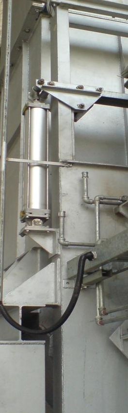
ENVIRONMENTAL IMPACT ASSESSMENT FOR PROPOSED CLINICAL WASTE TREATMENT PLANT AT TELUK KALONG INDUSTRIAL
  ESTATE, KEMAMAN, TERENGGANU FOR RADICARE (M) SDN BHD
                                                                            CHAPTER 5 – PROJECT DESCRIPTION

5.3.2 Clinical Waste Storage (Cold Room)

In a normal operation, the CW received will be immediately treated via the proposed incinerator. As a safety
measure, a cold room shall be provided to accommodate abnormal operation events such as plant shut
down, maintenance and over generation of CW, probably from disease outbreak etc. At the end of the day,
untreated CW will be stored in the cold storage area before being processed during the following day. There
will be cold room stores which can accommodate 250 tonnes per month and able to store untreated wastes
up to 16 days, temperature of below 6 °C.

5.3.3 Infrastructures and Utilities

5.3.3.1.1   Water Supply

Water supply requirement for ancillary facilities is estimated at 250m3/month (average). Among relevant
components are water supply distribution pipe, water pump house and storm water drainage.

5.3.3.1.2   Electricity

Electricity supply requirement for the incinerator is estimated about 50 kWh. Meanwhile for the ancillary
facilities the electricity requirement is 80 kWh (average).

5.3.3.1.3   Internet Network

The Project site requires internet speed of 4Mbps for computer networking.

5.3.3.1.4   Storm Water Drainage System

Storm water drainage system shall be prepared around the Project boundary. Storm water within the
Project area will be channelled to perimeter drainage system and it will be discharged to the existing
drainage system available within the Telok Kalong Industrial Estate.

5.3.3.1.5   Other Facilities

Sewerage treatment plant shall be provided with compliance to Standard B of the Environmental Quality
(Sewerage) Regulation 2009.The STP shall cater for about 30 personnel. The discharged from the
septic tank shall be to the nearest existing drain. Detail for the intended types of sewage treatment
system is attached in Appendix 5.3.3.

Other facilities to be included are main office, workshop, scheduled waste store, general room and staff
room.

5.3.4 Incinerator Plant

The incinerator plant will be divided in 2 phases, Phase 1 and Phase 2. For each phase the proposed
incinerator system is for an operation capacity of 15 MT/day (625 kg/hr) utilising rotary kiln type with
Flue Gas Thermal Oil (FGTO) heat exchanger. However, the design capacity is higher, at 18 MT/day
(750 kg/hr). Designed plant life is 20 years with thermal capacity 3,750,000 Kcal/hr or 15,750 MJ/hr.
An opened but roofed pad area will accommodate for combustion / incineration process block.
Components of the incinerator plant are summarised in the following subsection. Figure 5.3.1(a) shows
the layout of the Project components that consist of incinerator area, storage area (for clinical waste,
chemicals and ash), administration building and bin washing/ disinfection area.

        Chemsain Konsultant Sdn Bhd                                                                  Page | C5-2
                                                                                                Revision No. : 0
        CK/EV703/7024/18
                                                                                             Date : August 2019
ENVIRONMENTAL IMPACT ASSESSMENT FOR PROPOSED CLINICAL WASTE TREATMENT PLANT AT TELUK KALONG INDUSTRIAL
  ESTATE, KEMAMAN, TERENGGANU FOR RADICARE (M) SDN BHD
                                                                             CHAPTER 5 – PROJECT DESCRIPTION

5.3.4.1 Waste Feeding System

Automated with minimum manual intervention. Skip hoist system comprises of:

    a) A hydraulically operated automatic skip hoist mechanism
            Working pressure hydraulics: 100 barG
            Hydraulic oil: ARO ISO 46
            Max lifting weight (net): 250 Kg

    b) A hydraulically operated automatic skip tilting mechanism
            Working pressure hydraulics: 100 barG
            Hydraulic oil: ARO ISO 46
            Max tilting weight (net): 250 kg
            A bin holding structure: For standard 850 l or 240 l Euro bins

    c) A weighing unit
            Maximum load: 1000 kg
            Precision: 1 kg

                                               Plate 5.3.2: Skip Tilting Mechanism

            Plate 5.3.1: Skip Hoist
            Mechanism                          Plate 5.3.3: Bin Weighing Unit

5.3.4.1.1     Primary Combustion – Feeding Ram System

Features of the feeding ram system:

        Chemsain Konsultant Sdn Bhd                                                                  Page | C5-3
                                                                                                Revision No. : 0
        CK/EV703/7024/18
                                                                                             Date : August 2019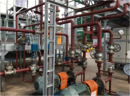
ENVIRONMENTAL IMPACT ASSESSMENT FOR PROPOSED CLINICAL WASTE TREATMENT PLANT AT TELUK KALONG INDUSTRIAL
ESTATE, KEMAMAN, TERENGGANU FOR RADICARE (M) SDN BHD
CHAPTER 5 – PROJECT DESCRIPTION
Feed hopper height is 5 meters, from where the waste is introduced.
Suitable level indication/switches are incorporated.
Suitable weight monitoring system is incorporated.
The bottom of the hopper that feeds to the incinerator has interlocks to protect the hopper from
the high temperature in the incinerator.
The bottom of the hopper is designed sufficiently strong to receive impact from the waste
dropping and not bend over time.
Dumping the waste from the feed hopper to the incinerator is monitored by the interlock system,
so that the incinerator is not overloaded or running without feed.
Feeding ram design is trouble free and very versatile.
A scraper will be installed to prevent waste from adhering onto the ram.
The ram has improved stiffeners to prevent it from bending over time.
Cooling water injection is foreseen in the feeding area.
The primary combustion comprises of:
Pneumatic cylinder working pressure: 8 barG
a) A Feed Hopper:
Power supply: 24VDC
Length: 1500 mm
Width: 1500 mm
Height: 2000 mm
Mild steel thickness: 10 mm
Working pressure: 100 barG
b) A Hydraulic Ram:
Length: 1250 mm
Width: 1000 mm
Height: 500 mm
Mild steel thickness: 16 mm
Working pressure pneumatic cylinder: 8 barG
c) A Guillotine Door:
Grease type door tracks: graphite or copper powder based
Insulation: refractory lined with concrete
Mild steel: 6 - 10 mm
Length: 250 mm
Width: 1500 mm
Height: 2100 mm
Refractory steel back plate: Included
Chemsain Konsultant Sdn Bhd Page | C5-4
Revision No. : 0
CK/EV703/7024/18
Date : August 2019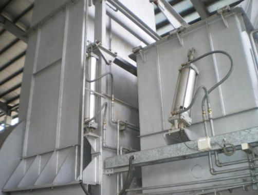
ENVIRONMENTAL IMPACT ASSESSMENT FOR PROPOSED CLINICAL WASTE TREATMENT PLANT AT TELUK KALONG INDUSTRIAL
ESTATE, KEMAMAN, TERENGGANU FOR RADICARE (M) SDN BHD
CHAPTER 5 – PROJECT DESCRIPTION
Plate 5.3.4: Feeding Hopper
Plate 5.3.6: Hydraulic Ram Plate 5.3.5: Guillotine Door
5.3.4.1.2 Primary Combustion – Incinerator
Features of the incinerator:
The incinerator is equipped with a diesel oil burner, which will start automatically when the
temperature in the kiln drops below a preset value.
There is a robust and foolproof ash collection system for the incinerator. No ash/ partially
burned waste shall be dropped from any part of the incinerator.
The incinerator comprises:
a) A Stationary Part
A stationary part that links the feed system to the rotary kiln and serving
as a flue gas collector between the kiln and the post combustion chamber
(mild steel sheet of 6 - 8 mm and is lined with an 85 % alumina containing
refractory concrete). The improved version includes the modification of the
voute above the feeding mouth and
Plate 5.3.7: Stationary Part
Chemsain Konsultant Sdn Bhd Page | C5-5
Revision No. : 0
CK/EV703/7024/18
Date : August 2019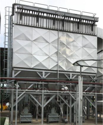
ENVIRONMENTAL IMPACT ASSESSMENT FOR PROPOSED CLINICAL WASTE TREATMENT PLANT AT TELUK KALONG INDUSTRIAL
 ESTATE, KEMAMAN, TERENGGANU FOR RADICARE (M) SDN BHD
                                                                            CHAPTER 5 – PROJECT DESCRIPTION

b) A Counter Current Rotary Kiln

The rotary kiln, which is a cylindrical combustion chamber in 10 mm mild steel sheet lined with 200 mm of
refractory concrete containing 85 % alumina. The refractory lined ash extraction flights at the rear of the
kiln have been redesigned. Refractory lining made of high alumina (85%) high density castable materials.
The kiln now has a VSD motor control with integrated management of motor parameters. This way,
automatic action can be taken in case of increased kiln friction. The specification kiln’s specification is
provided in Table 5.3.1.

                           Table 5.3.1: Counter Current Rotary Kiln Specification

   Type                                                      BIR 375
   External diameter                                         2000 mm
   Internal diameter                                         1600 mm
   Length                                                    4650 mm
   Volume                                                    12 m3
   Thermal capacity                                          3,75 Gcal/Hr
   Design CV of waste                                        2000 - 10.000 kcal/kg (8372 - 41860 kJ/kg)
   Residual organic carbon content of bottom ash             2 % maximum
   Operating temperature                                     900 °C to 1000 °C
   Rotary speed                                              1.5 rev/min (max.)
  Source: BIC Systems Asia Pacific Pte Ltd. (2018)

   Plate 5.3.8: Rotary Kiln                                   Plate 5.3.9: Rotary Motor

c) Kiln rotation CW/CCW
        Power: 2x2.2 Kw
        Tension: 3 x 400/50Hz + N
        Rotational speed outgoing shaft: 1.5 rpm
        Control: by VSD

       Chemsain Konsultant Sdn Bhd                                                                  Page | C5-6
                                                                                               Revision No. : 0
       CK/EV703/7024/18
                                                                                            Date : August 2019
ENVIRONMENTAL IMPACT ASSESSMENT FOR PROPOSED CLINICAL WASTE TREATMENT PLANT AT TELUK KALONG INDUSTRIAL
 ESTATE, KEMAMAN, TERENGGANU FOR RADICARE (M) SDN BHD
                                                                              CHAPTER 5 – PROJECT DESCRIPTION

d) A Cylindrical Section With Reduced Diameter For Ash Evacuation

Refractory lining made of high alumina (85%) high density castable
materials. Refractory steel (AISI 310) flame deflector for the burner flame
will be installed.
        External diameter: 1100 mm
        Internal diameter: 900 mm
        Length: 850 mm
        Volume: 0.7 m3
                                                                               Plate     5.3.10:   Reduced
                                                                               Cylindrical Section for Ash
                                                                               Evacuation

e) A Supporting Frame

Comprises of four supporting wheels and one trust wheel on self-
lubricating bearing and a motor redactor.

                                                                               Plate 5.3.11: Supporting Frame

f)   A Burner

Burner with thermal power rating of 90 kW and requires 3 x 400/50Hz
+ N power supply.

                                                                               Plate 5.3.12: Burner

g) A De-Ashing Chamber

Features of the de-ashing system:

The bottom ash bin replacement system is manually done for optimum reliability. The bins for ash
collection cannot be equipped with level sensors because of the presence of the burner flame. A timer
system is also not reliable to monitor the levels. These principles also apply to the de-ashing system for
the fly ash.

       Chemsain Konsultant Sdn Bhd                                                                    Page | C5-7
                                                                                                 Revision No. : 0
       CK/EV703/7024/18
                                                                                              Date : August 2019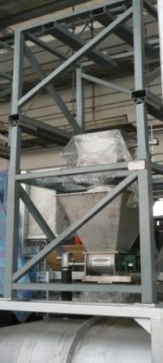
ENVIRONMENTAL IMPACT ASSESSMENT FOR PROPOSED CLINICAL WASTE TREATMENT PLANT AT TELUK KALONG INDUSTRIAL
ESTATE, KEMAMAN, TERENGGANU FOR RADICARE (M) SDN BHD
CHAPTER 5 – PROJECT DESCRIPTION
5.3.4.1.3 Secondary Combustion (Post Combustion)
Features of post combustion chamber:
Fuel/Air ratio is on auto-control
Fuel flow is measured and recorded
Lo, Lo-Lo, Hi and Hi-Hi temperature alarms are included
High temperature and low temperature trips are incorporated.
For the post combustion chamber, burner flame failure signal will trip the incinerator
The post combustion zone comprises of:
a) The upper part of the Stationary Zone
Plate 5.3.13: Post Combustion – Upper Part of Stationary
b) Two vertical cylindrical chambers
Specifications of the two vertical cylindrical chambers are listed in Table 5.3.2.
Table 5.3.2: Two Vertical Cylindrical Chambers Specification
Type BIR 375
Length 6000 mm
Width 1500 mm
Height -
Steel mild steel sheet 6 mm
Insulation lined with 150 mm refractory concrete 85 % alumina content
Inspection Inspection doors at bottom and top
Source: BIC Systems Asia Pacific Pte Ltd. (2018)
Chemsain Konsultant Sdn Bhd Page | C5-8
Revision No. : 0
CK/EV703/7024/18
Date : August 2019ENVIRONMENTAL IMPACT ASSESSMENT FOR PROPOSED CLINICAL WASTE TREATMENT PLANT AT TELUK KALONG INDUSTRIAL
ESTATE, KEMAMAN, TERENGGANU FOR RADICARE (M) SDN BHD
CHAPTER 5 – PROJECT DESCRIPTION
c) A Retractable Burner
The retracting mechanism is actuated by one single horizontal compressed air cylinder, protected
from radiant heat. The specifications of the retractable burner is provided in Table 5.3.3.
Table 5.3.3: Retractable Burner Specification
Type BIR 375
Thermal power rating 90 Kw
Power supply 3 x 400/50Hz + N
Working pressure pneumatic cylinder 8 barG
Source: BIC Systems Asia Pacific Pte Ltd. (2018)
Plate 5.3.14: Post Combustion – Retractable Burner
5.3.4.1.4 Flue Gas Pre-Cooling
A flue gas pre-cooling system consists of a flue gas inlet flange fitted with a butterfly valve operated
by a servo motor. Purpose is to reduce the temperature at the heat exchanger inlet below fusion point
of the particulates to avoid slagging. This system is to prevent any risk of corrosion. The specifications
of the flue gas pre-cooling system are provided in Table 5.3.4.
Table 5.3.4: Flue Gas Pre-Cooling
System Specification
Type BIR 375
Maximum inlet 1200 °C
temperature
Exit temperature 800 °C
Maximum flow rate 8000 Nm3/h
Source: BIC Systems Asia Pacific Pte Ltd. (2018)
Plate 5.3.15: Flue Gas Pre-Cooling
System
Chemsain Konsultant Sdn Bhd Page | C5-9
Revision No. : 0
CK/EV703/7024/18
Date : August 2019ENVIRONMENTAL IMPACT ASSESSMENT FOR PROPOSED CLINICAL WASTE TREATMENT PLANT AT TELUK KALONG INDUSTRIAL
ESTATE, KEMAMAN, TERENGGANU FOR RADICARE (M) SDN BHD
CHAPTER 5 – PROJECT DESCRIPTION
5.3.4.1.4.1 A Flue Gas to Thermal Oil Heat Exchanger
Features of the flue gas heat exchanger:
The heat exchanger is designed to be trouble-free
Online back blowing facility by ultrasonic soot blowers are foreseen to blow off accumulated soot
and dust
Vertical dual pass water (thermal fluid) tube heat exchanger has been designed for easy access
and maintenance. Large inspection doors at the inlet, as well as at the outlet of the exchanger allow
easy and quick access to the pipe bundles and allow quick cleaning by means of a vacuum cleaner
Automatic evacuation of fly ash by rotary valve into a removable steel bin with quick couplings
The specifications of the exchanger are provided in Table 5.3.5.
Table 5.3.5: Flue Gas to Thermal Oil Heat Exchanger Specification
Type BIR 375
Design inlet temperature 850 °C
Exit temperature 200 °C
Maximum flue gas flow rate 11000 Nm3/h
Source: BIC Systems Asia Pacific Pte Ltd. (2018)
Plate 5.3.16: Thermal Oil Heat Exchanger
5.3.4.1.4.2 A Thermal Oil Pump Skid
The new thermal oil system is designed for full automation. The system mainly features two identical
circulation pumps, one main and one back-up with auto switch-over with their respective shut off valves.
Low oil flow will trigger the stand by pump. Oil return Hi-Hi temperature will trigger incinerator trip.
Specification of the thermal oil pump skid is listed in Table 5.3.6.
Table 5.3.6: Thermal Oil Pump Skid
Type BIR 375
Electrical supply 3 x 400 V/ 50Hz + N
Pressure 2.0 bar
Flow rate 80 m3/h
Source: BIC Systems Asia Pacific Pte Ltd. (2018)
Chemsain Konsultant Sdn Bhd Page | C5-10
Revision No. : 0
CK/EV703/7024/18
Date : August 2019ENVIRONMENTAL IMPACT ASSESSMENT FOR PROPOSED CLINICAL WASTE TREATMENT PLANT AT TELUK KALONG INDUSTRIAL
ESTATE, KEMAMAN, TERENGGANU FOR RADICARE (M) SDN BHD
CHAPTER 5 – PROJECT DESCRIPTION
The system features a thermal filling pump and filling shut-off valves. Each pump can be separately
drained into a closed-loop drain system for spill-free and safe maintenance. The system also includes
a 3-way control valve for temperature control and a safety by-pass valve.
Plate 5.3.17: Thermal Oil Pump Skid
5.3.4.1.5 Sodium Bicarbonate (NaHCO3) Storing and Injection by Loss-in-Weight
Features of chemical dosing system:
Dosing chemical flow with feed rate adjustable according to the quantity and quality of flue gas
Dosing chemical flow indication by loss-in-weight feed back
No/Low sensors give alarm to warn operators
The dosing system is designed to prevent clogging of bicarbonate powder
Replacement of bags is done at floor level
FIBC’s are attached to an easy to handle and easy to install solid steel frame
The system has maximum mass flowrate of 25 kg/h and requires 3 x 400 V/ 50Hz + N of electricity
supply.
The advantage of using Bicarbonate instead of lime, is that the neutralising reaction time is much (five
times) shorter and the reaction itself nearly stoichiometric. This results in using less reactant and a more
complete reaction and a nearly null emission of acids to the atmosphere. Further, using less reactant,
means less fly ashes to be evacuated.
Chemsain Konsultant Sdn Bhd Page | C5-11
Revision No. : 0
CK/EV703/7024/18
Date : August 2019ENVIRONMENTAL IMPACT ASSESSMENT FOR PROPOSED CLINICAL WASTE TREATMENT PLANT AT TELUK KALONG INDUSTRIAL
ESTATE, KEMAMAN, TERENGGANU FOR RADICARE (M) SDN BHD
CHAPTER 5 – PROJECT DESCRIPTION
Plate 5.3.18: Sodium Bicarbonate Plate 5.3.19: Activated
Carbon Storing and Injection
Storing and Injection
5.3.4.1.6 Activated Carbon Storing and Injection by Loss-in-Weight
Features of chemical dosing system (similar to the above):
Dosing chemical flow with feed rate adjustable according to the quantity and quality of flue gas
Dosing chemical flow indication by loss-in-weight feed back
No/Low sensors give alarm to warn operators
The dosing system shall be designed to prevent clogging of bicarbonate powder
The system has maximum mass flowrate of 25 kg/h and requires 3 x 400 V/ 50Hz + N of electricity
supply.
5.3.4.1.7 Bag House Filter
Features of bag filter house/system include:
Auto back blow system on timer basis and on differential pressure basis, whichever triggers first
Manual back blow facility, which will override the auto settings
Bag filter, comes along with maintenance platform
Fly ash is collected at the bottom of the hoppers and is evacuated automatically by rotary air locks
into sealed container with automatic lid
The bag house filter specifications are provided in Table 5.3.7.
Table 5.3.7: Bag House Filter Specifications
Type BIR 375
Tension electrical supply 3 x 400 V/ 50Hz + N
Maximum air pressure 6 barG
Flow rate 30,000 m3/h
Design inlet temperature 200 °C
Chemsain Konsultant Sdn Bhd Page | C5-12
Revision No. : 0
CK/EV703/7024/18
Date : August 2019ENVIRONMENTAL IMPACT ASSESSMENT FOR PROPOSED CLINICAL WASTE TREATMENT PLANT AT TELUK KALONG INDUSTRIAL
ESTATE, KEMAMAN, TERENGGANU FOR RADICARE (M) SDN BHD
CHAPTER 5 – PROJECT DESCRIPTION
No. of sleeves 432
Material for sleeves Teflon needle felt
Removal of fly-ash By Rotary air locks
Efficiency 99.9%
Source: BIC Systems Asia Pacific Pte Ltd. (2018)
Plate 5.3.20: Bag House Filter
5.3.4.1.8 Exhaust Fan
Features of flue gas treatment system, in terms of emissions:
The flue gas treatment system is able to treat the flue gas to meet the emission standards
The exhaust fan speed is controlled by the negative pressure in the kiln
Table 5.3.8: Exhaust Fan Specifications
Type BIR 375
Tension electrical supply 3 x 400 V/ 50Hz + N
Power rating 110 kW
Maximum inlet temperature 250 °C
Maximum gas flow rate 600 m3/min
Maximum rotation speed 1500 rpm
Source: BIC Systems Asia Pacific Pte Ltd. (2018)
Chemsain Konsultant Sdn Bhd Page | C5-13
Revision No. : 0
CK/EV703/7024/18
Date : August 2019ENVIRONMENTAL IMPACT ASSESSMENT FOR PROPOSED CLINICAL WASTE TREATMENT PLANT AT TELUK KALONG INDUSTRIAL
ESTATE, KEMAMAN, TERENGGANU FOR RADICARE (M) SDN BHD
CHAPTER 5 – PROJECT DESCRIPTION
Plate 5.3.21: Exhaust Fan
5.3.4.1.9 Emission Monitoring Equipment
Highlighted features of emission monitoring equipment:
The emission monitoring equipment includes continuous recording and online monitoring system
for all the gas elements, as specified by the incinerator emission standards stipulated by the
Department of Environment Malaysia
Alarms are activated to notify the plant operator when the pre-set values are exceeded. If the
emission further crosses the limits, then incinerator will be tripped
Table 5.3.9: Emission Monitoring Equipment
Equipment Principle / Manufacturer
Extractive CO, CO2, SO2 analyser Principle of measurement: NDIR
Extractive NOx, O2 analyser Principle of measurement: CLD / Zirconia
HCL / HF analyser In-situ
Dust monitoring In-situ
SCADA The data of the monitoring system will be connected to
and integrated with the plant PLC/PC. Process interlocks
will not be implemented from the start but can be added
easily at a later stage if required. The plant supervision
PC will show and log all emission monitoring data
continuously.
CAL gases The system has provisions for connection of the
necessary CAL gas bottles.
Enclosure Weather-proof analyser system, cabinet construction
based on 2.0 mm thickness galvanised plate with powder
coated equipped with air condition unit and heating.
Equipped with power distribution panel, lighting, switch
and plug C/W cylinder rack.
Source: BIC Systems Asia Pacific Pte Ltd. (2018)
Chemsain Konsultant Sdn Bhd Page | C5-14
Revision No. : 0
CK/EV703/7024/18
Date : August 2019ENVIRONMENTAL IMPACT ASSESSMENT FOR PROPOSED CLINICAL WASTE TREATMENT PLANT AT TELUK KALONG INDUSTRIAL
ESTATE, KEMAMAN, TERENGGANU FOR RADICARE (M) SDN BHD
CHAPTER 5 – PROJECT DESCRIPTION
5.3.4.1.10 Peripherals
a) A hydraulic pack
Working pressure: 100 barG
Volume of oil tank: 250 l
Hydraulic oil: ARO ISO 46
Power electric motor: 11 kW
Tension electrical supply: 3 x 400 VAC/50Hz + N
Plate 5.3.22: Hydraulic Pack
b) A chimney
The chimney is equipped with the necessary sampling ports and access platform. The chimney is self-
supporting and of mild steel. Table 5.3.10 provides the specifications of the chimney.
Table 5.3.10:
Specification of Chimney
Type BIR 375
External diameter 1350 mm
Height 21 m
Flow volume of flue gas 5.1 m3/s
Exit velocity of flue gas 12 m/s
Temperature of flue gas 473.15 K
at inlet
Source: BIC Systems Asia Pacific Pte Ltd.
(2018)
Plate 5.3.23: Chimney Stack
Chemsain Konsultant Sdn Bhd Page | C5-15
Revision No. : 0
CK/EV703/7024/18
Date : August 2019ENVIRONMENTAL IMPACT ASSESSMENT FOR PROPOSED CLINICAL WASTE TREATMENT PLANT AT TELUK KALONG INDUSTRIAL
ESTATE, KEMAMAN, TERENGGANU FOR RADICARE (M) SDN BHD
CHAPTER 5 – PROJECT DESCRIPTION
c) An air compressor assembly
Features of air compressor assembly:
Careful location of the unit (dust-free) and preventive,
regular maintenance will render it trouble-free
Maximum working pressure: 8 barG
Flow rate: 2.85 m3/min
Plate 5.3.24: Air Compressor Assembly
d) Emergency by-pass
Features of emergency by-pass:
Emergency bypass system for the bag house filter is
fully automated
The bypass is a failsafe design (gravity opened) and is
interlocked with the process
When the bypass valve is open, the incinerator is
tripped
The bypass valve manual control is not allowed by law
The emergency by-pass consists of an automatic lid on top
of the emergency dump stack at the top of the post
combustion. A guillotine-type shut-off valve to isolate the Plate 5.3.25: Emergency By-pass
process downstream.
e) Fly ash evacuation system
A fly ash evacuation system comprises two dust hoppers, two rotary air locks and two easily replaceable
dust containers with semi-automatic lid.
Plate 5.3.26: Dust Hopper and Container
Chemsain Konsultant Sdn Bhd Page | C5-16
Revision No. : 0
CK/EV703/7024/18
Date : August 2019ENVIRONMENTAL IMPACT ASSESSMENT FOR PROPOSED CLINICAL WASTE TREATMENT PLANT AT TELUK KALONG INDUSTRIAL
ESTATE, KEMAMAN, TERENGGANU FOR RADICARE (M) SDN BHD
CHAPTER 5 – PROJECT DESCRIPTION
f) Liquids Injection Systems
The system consists of a volumetric injection pump (temperature controlled) and a compressed air
assisted injection nozzle. The flow rate is 500 l/h meanwhile the maximum pressure is 8 barG.
Plate 5.3.27: Liquid Injection System
g) Safety valve (Diluting air inlet)
The safety valve consists of an automatic control valve for controlled air ingress after the heat exchanger
(set point 200 °C).
Plate 5.3.28: Safety Valve
h) A Plant Automation System
Highlighted features of plant automation system
The plant is fully automatic, safe and user-friendly in all circumstances
Motor Control Center (MCC) and Programmable Logic Controls (PLC) are housed in a control room
All components are designed for the fail-safe conditions.
Chemsain Konsultant Sdn Bhd Page | C5-17
Revision No. : 0
CK/EV703/7024/18
Date : August 2019ENVIRONMENTAL IMPACT ASSESSMENT FOR PROPOSED CLINICAL WASTE TREATMENT PLANT AT TELUK KALONG INDUSTRIAL
ESTATE, KEMAMAN, TERENGGANU FOR RADICARE (M) SDN BHD
CHAPTER 5 – PROJECT DESCRIPTION
The plant automation system comprises of:
i. An MCC Power Switchboard - The switchboard houses all motor starters, variable speed drives
(VSD) and thermal overloads.
ii. A PLC Switchboard - The switchboard houses PLC and Ethernet modules.
Plate 5.3.29: MCC Power Switch Plate 5.3.30: PLC Switch Board
iii. A Pulpit Supervisory Control and Data Acquisition (SCADA) PC for User Interfacing - The pulpit is
equipped with a desktop PC with the LCD screen behind a protective window. A back-up PC runs
in parallel in a control room/rack room to render the system fail safe.
Plate 5.3.31: Control Panel Plate 5.3.32: PC Screen (Sample)
5.3.4.2 Truck and Bin Washing Bay
Washing bay will be provided near the weighing area for truck/ bin washing and cleansing upon tipping
of waste and prior to leaving the centre. Estimated 3.0 m3 of waste water generated from this washing
activity. Waste water from the washing bay will be channelled to the proposed Industrial Effluent
Treatment System (IETS) for treatment prior discharge.
Chemsain Konsultant Sdn Bhd Page | C5-18
Revision No. : 0
CK/EV703/7024/18
Date : August 2019ENVIRONMENTAL IMPACT ASSESSMENT FOR PROPOSED CLINICAL WASTE TREATMENT PLANT AT TELUK KALONG INDUSTRIAL
ESTATE, KEMAMAN, TERENGGANU FOR RADICARE (M) SDN BHD
CHAPTER 5 – PROJECT DESCRIPTION
5.3.5 Industrial Effluent Treatment System
The incinerator does not produce any waste water from the incinerator processes. Sources of waste
water are from wheel bins and trucks washing activities. Wheel bins are used for CW collection in clinical
facilities and trucks are used as to transport the collected CW (inside the bins) from clinical facilities to
the Project site. Waste water from the washing activities are considered to have potential infection risk
as the wheel bins and trucks are likely to be exposed to the CW. The amount of waste water is estimated
about 3 m3/day with capacity of 5m3/day. The waste water will be channelled to Industrial Effluent
Treatment System (IETS) that will be installed within the Project site. The IETS capacity is 5m3/day.
Chemical treatment to be applied and effluent shall comply with Standard B of the Environmental Quality
(Industrial Effluent) Regulations, 2009
The wastewater generated from bin wash will be piped to the IETS for treatment prior discharge to the
receiving body. The process flow block diagram of the wastewater treatment loading is as presented in
Figure 5.3.5.1, which is based on maximum capacity of 5m3/day.
The treatment processes for the wastewater are described as follows:-
a) Raw Wastewater
Wastewater from bin and truck washing area will be gravity flow to Collection Sump. From Collection
Sump, wastewater will be pumped to Equalization Tank. In the Equalization Tank, the wastewater will
be equalized via perforated air pipe which these pipes are connected to air compressor to provide
sufficient mixing and prevent the anaerobic condition of the raw wastewater. At a pre-determined level,
the homogenized wastewater will be pumped to Reaction Tank.
b) Physical-Chemical Treatment
i. Chemical Dosing
The physical-chemical treatment consists of Reaction Tank and primary Clarifier. Caustic will be dosed
to Reaction Tank automatically by a dosing pump to adjust the wastewater pH to optimum level for
chemical treatment. Coagulant will be dosed to coagulate non-biodegradable colloidal matter and
suspended solid. Polymer will be dosed automatically by a dosing pump to settle-off the flocs (Sludge).
ii. Primary Clarifier
The wastewater will be fed to center cone of Primary Clarifier to undergo solid – liquid separation
process. Flocculated sludge will be settled at the bottom of the tank which the tank is designed to cone
base to ease of sludge withdrawal for further dewatering. However, supernatant will be moved upward
to water surface and through baffle plates & v-notch weir overflow out from Primary Clarifier as clear
water.
c) Filtration System
The clarified water will be pumped to Sand Filter and Carbon Filter from Buffer Tank which act as
temporary storage. Sand Filter, the filtration medium has multiple layer of sand, where each layer with
a variety of size and different specific gravity. Activated Carbon Filter, the filtration medium has multiple
layers of sand, where each layer with a variety of size and different specific gravity and a layer of
activated carbon. Water is passed through these 2 filters to reduce the presence of suspended solids,
odour and colour in the water. The filters need to be periodically cleaned (backwash) for 15-20 minutes
Chemsain Konsultant Sdn Bhd Page | C5-19
Revision No. : 0
CK/EV703/7024/18
Date : August 2019ENVIRONMENTAL IMPACT ASSESSMENT FOR PROPOSED CLINICAL WASTE TREATMENT PLANT AT TELUK KALONG INDUSTRIAL
ESTATE, KEMAMAN, TERENGGANU FOR RADICARE (M) SDN BHD
CHAPTER 5 – PROJECT DESCRIPTION
over the duration of the usage. The treated water will be discharged into drainage system as Final
Discharge.
4. Sludge Management
Settled sludge from Primary Clarifier will be transferred via air diaphragm pump into Sludge Tank for
storage before collected by tanker.
The IETS is to be designed to treat wastewater from the facility with the influent characteristic as shown
in Table 5.3.11. to be compare with design value in compliance to Standard B of Environmental Quality
(Industrial Effluent) Regulations 2009.
Table 5.3.11 : Characteristic of Raw Wastewater to the Wastewater Treatment Plant Design
Value
Characteristic of the raw Design value to comply
Parameter
wastewater from bin washing* to Standard B
pH 7.5 - 10.4 5.5 - 9.0
BOD (mg/L) ≤46 ≤ 50
COD (mg/L) ≤145 ≤ 200
Suspended Solids (mg/L) ≤32 ≤100
Oil and grease (mg/l) ≤5 ≤10
Cadmium (mg/l) ≤0.352 ≤0.02
Lead (mg/l) ≤5.79 ≤0.5
*The characteristic of the raw wastewater is derived from Radicare’s Teluk Panglima Garang wastewater sampled.
The removal efficiency of these operation scenario is 95% for cadmium and 92% for lead. The detailed
calculation for the IETS mass balance is shown in Appendix 5.3.5.
Process Flow Diagram of the IETS Treatment Process incorporation the treatment of wastewater is
shown in Figure 5.3.5.2.
5.3.6 Sewage Treatment
Sewage treatment shall be provided with compliance to Environmental Quality (Sewerage) Regulation
2009. It shall cater for about 30 personnel. Treated discharges from the septic tank shall be diverted to
the nearest existing drain. The estimated P.E. for the site is PE 9.
The proposed septic tank for the site is the KOSSAN FRP Septic Tank approved by SPAN for serving
PE 12. Details on the selected treatment plant system of Standard B of Environmental Quality (Sewage)
Regulation 2009 is attached in the Appendix 5.3.3.
Chemsain Konsultant Sdn Bhd Page | C5-20
Revision No. : 0
CK/EV703/7024/18
Date : August 2019BLOCK DIAGRAM AND
MASS BALANCE
FIGURE 5.3.5.1
CHEMSAIN KONSULTANT SDN. BHD.FIGURE 5.3.5.2
ENVIRONMENTAL IMPACT ASSESSMENT FOR PROPOSED CLINICAL WASTE TREATMENT PLANT AT TELUK KALONG INDUSTRIAL
  ESTATE, KEMAMAN, TERENGGANU FOR RADICARE (M) SDN BHD
                                                                               CHAPTER 5 – PROJECT DESCRIPTION

5.4      Design Criteria of the Thermal Treatment Facility

5.4.1 Key Design Parameters

The thermal treatment facility is designed according to European Union (EU) standards. The key design
aims to fulfil typical regulatory requirements to date, with the key parameters being Destruction
Efficiency (DRE %) of 99.9999%, minimum residence time of minimum two seconds at 1,100 °C in the
post combustion. The Operating Standards are listed in Table 5.4.1.
                                Table 5.4.1: Incinerator Operating Standards
      Item                                                       Specifications
      Destruction efficiency (DRE)                               99.9999 %
      Primary Combustion Chamber Temperature                     850 °C minimum / 1,000 °C maximum

      Secondary Combustion Chamber Temperature                   1,100 °C minimum / 1,200 °C maximum

      Residence Time                                             Minimum 2 seconds
      Minimum Oxygen Content                                     12%-13%
      Air / Fuel Ratio                                           2.5
  Source: BIC Systems Asia Pacific Pte Ltd. (2018)

The other key parameter is the conformance to emission standards in Malaysia. The limits are in Table
5.4.2. The EU standard, which is the design standard used by BIC Systems Asia Pacific Pte Ltd is
equally or more stringent than Malaysian standard.
                  Table 5.4.2: Emission Standards –European Union and Malaysia
   Parameter                     EU (Daily)   EU (Hourly)   EU ( 4- Hour)    EU Summary         Malaysia*

                                                                mg/m3
   Ash / Particulates                  5          10             -                  5               100
   HF                                   -          -              -                  -                1
   HCl                                 5          10              -                 5                40
   CO                                  50        100              -                 50               50
   NOx                                 100       200              -                100              200
   SOx                                 25         50              -                 25               50
   Cd                                   -          -            0.05               0.05             0.05
   Hg                                   -          -            0.05               0.05             0.05
   Pb                                   -          -              -                  -                 -
   Heavy Metals                         -          -              -                  -               0.5
   Dioxin / Furan                       -          -         0.10 ng/m3        0.10 ng/m3       0.10 ng/m3
   Total Organics                      5          10              -                 5                10
 Note: Environmental Quality (Clean Air) Regulations 2015 (3rd Schedule Regulation 13, Item K: Waste Incinerator
 in All Sizes.
 Source: BIC Systems Asia Pacific Pte Ltd. (2018)

         Chemsain Konsultant Sdn Bhd                                                                   Page | C5-21
                                                                                                   Revision No. : 0
         CK/EV703/7024/18
                                                                                                Date : August 2019
ENVIRONMENTAL IMPACT ASSESSMENT FOR PROPOSED CLINICAL WASTE TREATMENT PLANT AT TELUK KALONG INDUSTRIAL
ESTATE, KEMAMAN, TERENGGANU FOR RADICARE (M) SDN BHD
CHAPTER 5 – PROJECT DESCRIPTION
The design also considers the typical chemical composition of clinical waste as shown in Table 5.4.3.
Table 5.4.3: Typical Clinical Waste Chemical Composition
Element Mass % Mol/kg
C 74.80 0.062
H 7.00 0.070
N 1.00 0.001
S 1.000 0.000
Hg 0.00 0.000
Pb 0.000 0.000
Zn 0.000 0.000
0.000 0.000 0.000
Cl 1.00 0.000
F 0.10 0.000
Br 0.10 0.000
O 5.00 0.003
Ash 10.000 -
Total 100.00 -
Source: BIC Systems Asia Pacific Pte Ltd. (2018)
Summary of design and operational particulars of the thermal treatment facility are as listed in Table
5.4.4. The plant is designed to operate at a capacity of per line of 625 kg/hr where 15 MT/day of clinical
wastes are expected to be treated. With the implementation of Phase 2, a total of 30 MT/day if wastes
shall be treated.
Table 5.4.4: Summary of General Technical Characteristic of the Thermal Treatment Facility
Thermal Capacity 3,750,000 Kcal/hr (15,750 MJ/hr)
Throughput 625 kg/hr (15 MT/day) x 2 units
(Based on the average calorific value of waste of 4500 kcal/kg (20
MJ/kg)
Design Life Span 20 years
Process Line 2
Operating Hours 24 hours per day, 7 days per week
Waste storage capacity 90 MT
Incinerator System Counter Current Rotary Kiln
Destruction efficiency (DRE) 99.9999 %
Feeding Loading Skip hoist system
Start-up Duration 8 hours to automatically heat up to operating temperature
(depending on atmospheric conditions)
Burn period 8 hours
Chemsain Konsultant Sdn Bhd Page | C5-22
Revision No. : 0
CK/EV703/7024/18
Date : August 2019ENVIRONMENTAL IMPACT ASSESSMENT FOR PROPOSED CLINICAL WASTE TREATMENT PLANT AT TELUK KALONG INDUSTRIAL
ESTATE, KEMAMAN, TERENGGANU FOR RADICARE (M) SDN BHD
CHAPTER 5 – PROJECT DESCRIPTION
Burn Cycle 8 cycles (160 kg per loading)
Residential time 2 – 3 seconds
Cool Down Period 24 hours
Auxiliary Fuel Diesel - 50 l/hr (for start-up only)
Air Pollution Control System
Heat Removal Heat exchanger: flue gas to thermal oil
Dioxin and Furan Control Continuous operation creating steady state conditions,
ensuring complete combustion leading to complete
destruction of dioxins and furans (dioxins can completely be
eliminated with a residence time of 2 seconds at 1000°C and
oxygen level of min 10% is thoroughly distributed)
Dosing of Activated Carbon to remove any remaining dioxin
and furan
Acidic Gas Neutralizer Dosing of Sodium Bicarbonate
Dust Filtration Baghouse: 432 Teflon Felt bags
Parameter of CEMS Conformity with EC and Malaysian emission regulations
Ash Removal Daily
Utilities
Power supply 50 kW/hr (average)
Estimated waste
Fly ash 16 kg/hr (PM) and 72 kg/hr (Salts)
Bottom ash 64.28 kg/hr
5.5 Process Description
5.5.1 Handling of Clinical Wastes at Source (On-Site Handling)
SW 403, SW 404, SW 409, SW410, SW 429 and SW 430 will be collected and transported from the
respective hospitals and laboratory to the Project site using dedicated trucks. Composition of clinical
waste received at Teluk Panglima Garang Plant are listed in Table 5.5.1. Clinical wastes analysis are
listed in Table 5.5.2 and Table 5.5.3.
Table 5.5.1: Composition of Clinical Waste Received at Teluk Panglima Garang Plant
Material Percentage
Mixed papers 14.13
Plastics 39.21
Diapers 7.32
Surgical garments 11.11
Gloves 15.6
Absorbent 12.63
Total 100
Source: TPG’S Radicare Sdn Bhd. (2009)
Chemsain Konsultant Sdn Bhd Page | C5-23
Revision No. : 0
CK/EV703/7024/18
Date : August 2019ENVIRONMENTAL IMPACT ASSESSMENT FOR PROPOSED CLINICAL WASTE TREATMENT PLANT AT TELUK KALONG INDUSTRIAL
ESTATE, KEMAMAN, TERENGGANU FOR RADICARE (M) SDN BHD
CHAPTER 5 – PROJECT DESCRIPTION
Table 5.5.2: Proximate Analysis of Clinical Waste
Analysis Range (%) Average (%)
Moisture ontent 16.9 - 28 21
Ash Content 1.6 - 4.7 3.1
Volatile matter 66.1 - 77.2 72.2
Fixed Carbon 1.2 - 4.3 3.2
Adapted from: Radicare (M) Sdn Bhd. (2012)
Table 5.5.3: Ultimate Analysis of Clinical Waste
Component Weight Percentage (%)
Carbon 51.83
Hydrogen 8.63
Oxygen 35.53
Nitrogen 0.17
Sulphur 0.10
Chlorine 0.64
Ash 3.1
Adapted from: Radicare (M) Sdn Bhd. (2012)
Collection and storage of clinical wastes in Clinical Wastes Management Services (CWMS) is one of
Radicare’s responsibilities as the Concession Company. As such, relevant products (i.e. receptacles,
plastic bags and on-site containers) are to be supplied to the hospitals or establishments to contain
clinical wastes.
Segregation of the clinical wastes is done by MOH’s staff in accordance to Management of Clinical and
Related Wastes in Hospital and Health Care Establishments (1993) and Project Operations Guidelines
on Clinical Wastes Management Services (2009) released by the MOH.
Clinical wastes that have been segregated are stored in dedicated containers/ plastic bags before being
sealed and labelled. Once the plastic bags or sharp containers are sealed, it is strictly prohibited to
break the seal. They are handled with care to prevent accidental tears or breaks until the incineration
process, as it may cause health and environmental hazards.
Table 5.5.4 presents types of products approved by the MOH to be used for containment of CW
generated at source.
Plastic bags and sharp containers are then transported in wheeled bins to the hospital’s central storage
for collection by Radicare staff. Collection of clinical wastes shall be done daily or as frequently as
circumstances demand. Authorised representative of the MOH and Radicare staff weight the clinical
wastes and record the quantities and weights. During the collection of the wheeled bins containing
clinical wastes, Radicare staff shall provide adequate supply of plastic bags, sharp containers and
cleaned receptacles for the collection and on-site storage. Consignment notes are completed for each
collection. Both the MOH’s staff and Radicare staff are well-trained and equipped with personal
protective equipment (PPE) during the handling process.
Chemsain Konsultant Sdn Bhd Page | C5-24
Revision No. : 0
CK/EV703/7024/18
Date : August 2019ENVIRONMENTAL IMPACT ASSESSMENT FOR PROPOSED CLINICAL WASTE TREATMENT PLANT AT TELUK KALONG INDUSTRIAL
ESTATE, KEMAMAN, TERENGGANU FOR RADICARE (M) SDN BHD
CHAPTER 5 – PROJECT DESCRIPTION
Table 5.5.4: Approved Products Used for CWMS
Purpose Products Used
Segregation of sharps and Yellow-coloured triple-lock
syringes container (20L, 10L, 5L and
2.5L)
Segregation of non-sharps Yellow-coloured plastic
clinical wastes bags
Holding of non-sharps clinical Bag Holder (Size 18L &
wastes 35L)
Sealing and tagging of plastic One-way
bags during collection plastic seal
For collection and Yellow-coloured wheeled
transportation of clinical waste bin (240L)
This Project will accommodate clinical wastes generated from government hospitals and laboratory in
East Coast Peninsular Malaysia namely Pahang, Terengganu and Kelantan. Estimated quantities of
clinical wastes to be collected and treated at the Project site are listed in Table 5.5.5. and Figure 5.5.1.1
shows the Handling of Clinical Waste at Source (On-Site Handling)-by MOH staffs.
Chemsain Konsultant Sdn Bhd Page | C5-25
Revision No. : 0
CK/EV703/7024/18
Date : August 2019ENVIRONMENTAL IMPACT ASSESSMENT FOR PROPOSED CLINICAL WASTE TREATMENT PLANT AT TELUK KALONG INDUSTRIAL ESTATE, KEMAMAN, TERENGGANU FOR RADICARE (M) SDN BHD
CHAPTER 5 – PROJECT DESCRIPTION
Table 5.5.5: Clinical Wastes Collection from Waste Generators
LIST OF GOVERNMENT HOSPITALS LIST OF PRIVATE CLINICS AND CLINICAL CENTRES
Name MT/Yr Name MT/Yr Name
Pahang Kelantan Pahang
Hospital Besar Kuantan 450.24 Hospital Kota Bharu 437 Wasco Coating Malaysia Sdn Bhd
Hospital Pekan 39 Hospital Kuala Krai 79 Unit Hemodialisis PDRM
Hospital Bentong 48 Hospital Machang 34.4 RP Chemicals (M) Sdn Bhd
Hospital Kuala Lipis 84.1 Hospital Pasir Mas 40.3 Hospital Pakar PRKMUIP Sdn Bhd
Hospital Raub 34 Hospital Pasir Putih 33.5 Saznoor Industries Sdn Bhd
Hospital Jerantut 34.4 Hospital Tanah Merah 101.1 Pusat Dialisis NKF-Sang Riang, Triang
Hospital Jengka 43.5 Hospital Tumpat 33 Pusat Dialisis NKF-Tun Abdul Razak
Hospital Rompin 7.2 Hospital Gua Musang 29.5
Hospital Muadzam Shah 31.2 Hospital Jeli 22 Terengganu
Hospital Cameron Highland* 7.5
Universiti Teknologi Mara, Terengganu
Hospital Temerloh 348.5
Pusat Kesihatan Pelajar, Universiti Malaysia Terengganu
Fakulti Perubaatan Sains Kesihatan
Pusat Dialisis NKF-Kuala Terengganu
Pusat Dialisis NKF-Yayasan Buah Pinggang Kemaman
Chemsain Konsultant Sdn Bhd Page | C5-26
Revision No. : 0
CK/EV703/7024/18
Date : August 2019ENVIRONMENTAL IMPACT ASSESSMENT FOR PROPOSED CLINICAL WASTE TREATMENT PLANT AT TELUK KALONG INDUSTRIAL ESTATE, KEMAMAN, TERENGGANU FOR RADICARE (M) SDN BHD
CHAPTER 5 – PROJECT DESCRIPTION
Table 5.5.5: Clinical Wastes Collection from Waste Generators (Cont.)
LIST OF GOVERNMENT HOSPITALS LIST OF PRIVATE CLINICS AND CLINICAL CENTRES
Terengganu MT/Year Kelantan
Hospital Kuala Terengganu 412.8 Fakulti Industri Asas Tani
Hospital Dungun 42 Fakulti Perubatan Veteriner
Pusat Dialisis NKF
Hospital Hulu Terengganu 34.6
HUSM
Hospital Besut 51.5
Hospital Kemaman 110.3
Hospital Setiu 23.4
*CW will be collected by other concession company.
Source: Radicare (M) Sdn Bhd. (2018)
Chemsain Konsultant Sdn Bhd Page | C5-27
Revision No. : 0
CK/EV703/7024/18
Date : August 2019Collection,
segregation, storage
in dedicated Put in wheeled bin
containers/ plastic
bags
Weight and record
quantities and weights Stored at hospitals
Preparation of central storage
Consignment note
Transportation to
Radicare’s Plant
via designated routes
FIGURE 5.5.1.1 : Handling of Clinical Waste at Source (On-Site Handling)-by MOH staffsENVIRONMENTAL IMPACT ASSESSMENT FOR PROPOSED CLINICAL WASTE TREATMENT PLANT AT TELUK KALONG INDUSTRIAL
ESTATE, KEMAMAN, TERENGGANU FOR RADICARE (M) SDN BHD
CHAPTER 5 – PROJECT DESCRIPTION
5.5.2 Transportation of Clinical Wastes to Project Site
Transportation of wheeled bins from the hospitals to the Proposed Project shall be via dedicated
transportation route by means of five units of licensed trucks owned by Radicare with a capacity of 11
tonnes each. In the wheel bin, plastic bags containers are properly sealed and secured for easy
transportation as well as to ensure no leakage or odour emitted during the transportation process. It is
estimated that there will be one trip of delivery daily for each truck where the truck shall collect CW from
respective hospitals and health facilities to the Proposed Project site located in Teluk Kalong Industrial
Estate shown in Table 5.5.6. The flow diagram for the waste transportation shown in Figure 5.5.2.1.
Table 5.5.6: Transportation and collection of the CW are daily and divided by 4 routes
Area of CW Collection Route
Kuantan, Hulu Terengganu, Kuala Terengganu, Kuala Terengganu-Kemaman-Lebuhraya Jabor-
Dungun, Kemaman Jerangau-Hulu Terengganu-Jalan Pantai-
Dungun-Kemaman-Kuantan
Muadzam Shah-Pekan-Temerloh Kuantan-Pekan-Muadzam Shah-Temerloh-
LebuhRaya Pantai Timur-Kemaman-Kuantan
Jengka-Jerantut-Temerloh Kuantan-Jengka-Jerantut-Temerloh-Lebuhraya
Pantai Timur-Kemaman-Kuantan
Tumpat, Pasir Mas, Tanah Merah, Machang, Jeli, Kota Bharu-Tumpat-Pasir Mas-Tanah Merah-
Kuala Krai, Gua Musang, Kota Bharu, HUSM, Jeli-Machang-HUSM-Pasir Putih-Besut-Setiu-
Pasir Putih, Besut, Setiu Gua Musang-Kuala Krai-Kota Bharu
Source : Radicare (M) Sdn. Bhd. 2018
5.5.3 Handling of Clinical Wastes at Project Site (Off-site Handling)
Clinical wastes received at the Project site will be weighed before further handling and treatment.
5.5.4 Incineration Process
Block diagram for the overall processes proposed to be undertaken at the thermal treatment facility
(incinerator plant) is shown in Figure 5.5.4.1.
The clinical wastes contained in standard 660 L or 240 L plastic waste bins is fed into the system with
a skip hoist system. The feeding process is automated with minimum manual intervention. In exception
of placing bins in position, the rest of the process including lifting, tilting, as well as lowering the bins
are fully automated.
The primary combustion train comprises a feeding hopper, a hydraulic ram that pushes the waste and
a guillotine (fire) door that opens only when waste is pushed into combustion chamber. The dumping
of the waste from the feeding hopper to the incinerator is monitored by interlock system, to eliminate
the possibility of overloading or under-loading of waste. The hydraulic ram will be scraped by guillotine
door so that no adhering of waste onto the feeding ram. Meanwhile, cooling air will be aspired through
the feeding area, to cool it down.
Chemsain Konsultant Sdn Bhd Page | C5-28
Revision No. : 0
CK/EV703/7024/18
Date : August 2019Collection of
Clinical Waste from
Hospital and
Laboratory
Designated Designated
Routes Routes
Transporting
Delivery of Clean
Clinical Waste from
Wheel Bin to
Hospital to
Hospital
Incinerator Plant
Treatment Plant
Treatment Inside Arrival of Trucks
Thermal Treatment Containing
Plant Collected CW
Generation of bottom ash
and fly ash SW406
Disposal of SW406 to Kualiti Alam
FIGURE 5.5.2.1 Flow Diagram Waste TransportationENVIRONMENTAL IMPACT ASSESSMENT FOR PROPOSED CLINICAL WASTE TREATMENT PLANT AT TELUK KALONG INDUSTRIAL
ESTATE, KEMAMAN, TERENGGANU FOR RADICARE (M) SDN BHD
CHAPTER 5 – PROJECT DESCRIPTION
A stationary part links the feed system to the rotary kiln and serves as a solid hearth bed to start and to
preheat the freshly introduced waste. After being partly burnt, the solid waste enters a counter current
rotary kiln for further complete combustion. The cylindrical rotary kiln rotates clockwise or counter-
clockwise at a controllable speed, to ensure thorough and speedy combustion. A cylindrical section at
the rear end of the kiln serves as an ash evacuation portion. The entire rotary kiln is supported by four
supporting wheels and one trust wheel on self-lubricating bearings.
The air inlet at the Heat Exchanger is to limit its inlet temperature to 900°C to prevent clogging of the
pipe bundles in the Heat Exchanger (Flue gas at the exit of SCC is at around 1000°C and it contains
particulates - Fly Ash, which melt above 900°C). By reducing the temperature to 900°C, the particulates
remain solid and therefore do not stick to the pipe bundles of the Heat Exchanger. Hence no clogging
of the Heat Exchanger by Fly Ash.
To raise the temperature at start-up, the incinerator is equipped with a diesel burner. The burner will
start firing automatically when the temperature inside the kiln drops below a pre-set value. There will
be a robust and fool proof ash collection system for the incinerator. The new design can ensure that no
ash nor partially burnt waste shall drops from any part of the incinerator. In addition, replacement of the
bottom ash bin will be manually done for optimum reliability.
The secondary combustion, also known as post combustion chamber, starts at the upper part of the
stationary part, followed by an extension chamber equipped with and retractable burner.
Chemsain Konsultant Sdn Bhd Page | C5-29
Revision No. : 0
CK/EV703/7024/18
Date : August 2019ENVIRONMENTAL IMPACT ASSESSMENT FOR PROPOSED CLINICAL WASTE TREATMENT PLANT AT TELUK KALONG INDUSTRIAL ESTATE, KEMAMAN, TERENGGANU FOR RADICARE (M) SDN BHD
CHAPTER 5 – PROJECT DESCRIPTION
Refractory lined
Source: BIC Systems Asia Pacific Pte Ltd. (2018)
Figure 5.5.4.1: Process Flow Block Diagram
Chemsain Konsultant Sdn Bhd Page | C5-30
Revision No. : 0
CK/EV703/7024/18
Date : August 2019ENVIRONMENTAL IMPACT ASSESSMENT FOR PROPOSED CLINICAL WASTE TREATMENT PLANT AT TELUK KALONG INDUSTRIAL ESTATE, KEMA
5.5.4.1 Gas Cooling
After combustion, the flue gas will first enter a flue gas cooling system. The flue gas will be directed in
to a Flue Gas Thermal Oil (FGTO) heat exchanger. The vertical thermal heat exchanger enables easy
access and maintenance. The trouble-free design of the vertical FGTO heat exchanger is equipped
with ultrasonic soot blowers, in order to blow off accumulated fly-ash and soot. The newly designed
thermal oil system, fully automatically triggers the stand-by pump in case of low oil flow, where Hi-Hi
temperature will trigger plant trip (emergency by-pass).
The air inlet at the Heat Exchanger is to limit its inlet temperature to 900°C to prevent clogging of the
pipe bundles in the Heat Exchanger (Flue gas at the exit of SCC is at around 1000°C and it contains
particulates - Fly Ash, which melt above 900°C). By reducing the temperature to 900°C, the particulates
remain solid and therefore do not stick to the pipe bundles of the Heat Exchanger. Thus no clogging of
the Heat Exchanger by Fly Ash is expected.
5.5.4.2 Incinerator Plant Control System
The entire incinerator plant is automatically controlled by a PLC (Programmable Logic Controller). All
required instrumentation for the incineration system, the waste feed system, the rotary kiln, the post
combustion chamber, the flue gas treatment and scrubbing system, the fan controls and emergency
by-pass system are included. The incinerator controls include temperature controls, pressure controls,
excess air controls, all burner safeties and the necessary alarms/alert and data logging equipment.
5.5.4.3 Clinical Waste Storage
In the event that clinical wastes could not be incinerated within 24 hours of reception, they will be stored
in a dedicated storage container/ refrigerator at temperature of between below 6˚C (cold storage).
There are six storage containers available at the Project site. Total holding capacity is 250 MT.
5.5.4.4 Cleansing and Disinfection of Wheeled Bins and Trucks
Upon unloading of clinical wastes at the reception area, the emptied wheeled bins will be transferred to
the washing bay area. Wheeled bins will be washed, sprayed with biodegradable disinfectant solution
and rinsed before being transferred to clean bin storage area. Trucks will also be cleaned and
disinfected before the next collection trip or usage. Clean wheeled bins will be returned to the clinical
wastes generators (hospitals).
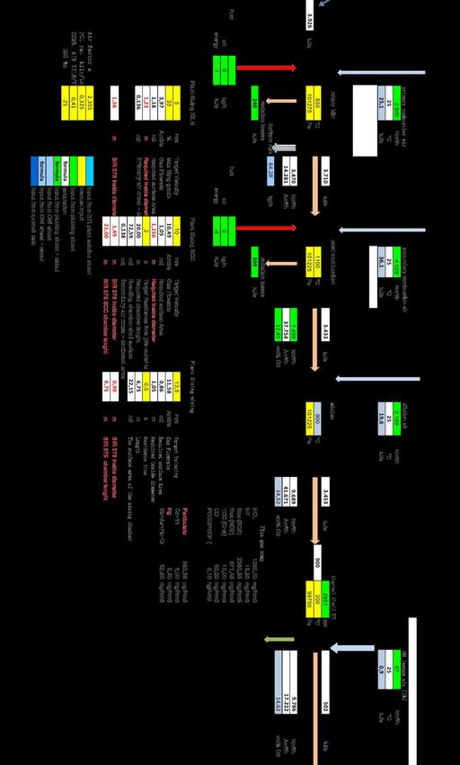
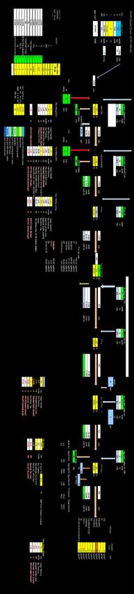
5.5.4.5 Thermal Treatment Facility’s Mass Balance
The thermal treatment facility’s mass balance is shown in Figure 5.6.1a and Figure 5.6.1b
5.6 Pollution Control System and Waste Management
5.6.1 Air Pollution Control
The Air Pollution Control (APC) that will be installed at the thermal treatment facility includes a dry
scrubber (with sodium bicarbonate (NaHCO3) and activated carbon storing and injection systems) and
a bag house filter.
Chemsain Konsultant Sdn Bhd Page | C5-31
Revision No. : 0
CK/EV703/7024/18
Date : August 2019ENVIRONMENTAL IMPACT ASSESSMENT FOR PROPOSED CLINICAL WASTE TREATMENT PLANT AT TELUK KALONG INDUSTRIAL ESTATE, KEMA
Sodium Bicarbonate will be used for acidic gas neutralizer. The advantage of using Sodium Bicarbonate
instead of lime, is that the neutralising reaction time is much (five times) shorter and the reaction itself
nearly stoichiometric. Activated carbon will be used to remove any remaining of Dioxin and Furan in the
flue gases.
Sodium bicarbonate and activated carbon are stored and injected according to loss-in-weight. The new
chemical dosing design is such that it will dose the chemical flow with adjustable feeding rate according
to the quantity and quality of the flue gas. The dosing of chemical flow is by loss-in-weight feedback.
The operators will be notified by the No/Low sensor together with alarms. Moreover, the dosing system
is designed to prevent clogging of bicarbonate powder.
The flue gas then will enter the bag house filter to remove particulates and dust. A pulsating compressed
air system will blow-off the filtered dust from the filter bags and be triggered by differential pressure
across the bags. A large maintenance platform is installed at the top of the bag-house. Rotary air locks
will collect the fly-ash and the collected fly-ash drops by gravity into sealed containers with automatic
lid. The exhaust fan speed is controlled by the negative pressure in the kiln. The flue gas treatment
system is able to treat the flue gas to meet the emission standards.
5.6.1.1 Emission Monitoring
Emission monitoring equipment installed at the incinerator will comprise of in-situ CO, CO2, SO2
analysers which adopt NDIR measurement principle; extractive NOx, O2 analysers which adopt CLD /
Zirconia measurement Principle; in situ HCL/HF analysers and in-situ dust monitoring system. With
SCADA, the data of the monitoring system will be connected and integrated with the plant PLC/PC.
The plant supervision PC will show and log all emission monitoring data continuously. The compact
emission monitoring system is enclosed with a weather proof analyser cabinet, equipped with air
condition unit, power distribution panel, lighting, switch and plug C/W rack.
The emission monitoring equipment can continuously record and online monitor all gas components
that are specified by the Malaysian Authorities. Alarms are activated to notify when the present value
are exceeded. If the pre-set values are further exceeded, the incinerator will trip. The emission
monitoring enclosure will be installed on the ground floor level, at the chimney base. The trial burn
results from the Teluk Panglima Garang incinerator shall be made as references for the prediction of
emitted pollutants explained in Chapter 6.
5.6.1.2 Air Emission Limit
Air emission from the Project shall comply with emission limits based on Activity K: Waste Incinerators
in All Sizes under the Third Schedule of Environmental Quality (Clean Air) Regulations 2014 as listed
in Table 5.6.1.
Table 5.6.1: Air Emission Limit- Activity K-CAR 2014
Activity K
Parameter
Limit Values Monitoring
3
Total PM 100 mg/m Continuous
3
NMVOC as total organic carbon 10 mg/m Continuous
3
Hydrogen Chloride (HCl) 40 mg/m Continuous
3
Hydrogen Fluoride (HF) 1 mg/m Continuous
Chemsain Konsultant Sdn Bhd Page | C5-32
Revision No. : 0
CK/EV703/7024/18
Date : August 2019You can also read