Installation, Operation & Maintenance Manual Energy Storage System (ESS) Storion-SMILE5 (AU) - V02 - GC Solar online Shop
←
→
Page content transcription
If your browser does not render page correctly, please read the page content below
Installation, Operation & Maintenance

              Manual

   Energy Storage System (ESS)

        Storion-SMILE5 (AU)

                                 V02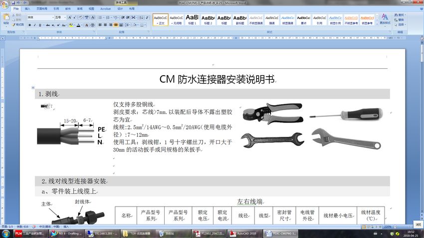
Your Smart Energy                             Introduction

  Copyright Statement

  This manual is under the copyright of Alpha ESS Co., Ltd. with all rights reserved. Please keep the
  manual properly and operate in strict accordance with all safety and operating instructions in this
  manual. Please do not operate the system before reading through the manual.

  Version Information

   Version         Date               Content

                                      Notes are added for better overview purposes. RJ45
   V1.6            02022018
                                      connecting diagram was updated.

                                      Figures changed after firmware version update.
   V1.7            06032018           Figures and installation steps changed after new pre-wired
                                      cable configuration in CB.

   V1.72           14052018           Package parts list modified. Power definition modified.
                                      ADL3000 3-phase connection added.

                                      Daily maintenance content added, installation environment
   V1.74           22092018           requirements and parameters in DS. EMS display indication
                                      modified.

   V1.76           05112018           Differentiation of outdoor and indoor versions.

   V02             25092019           Off-grid application removed; two wirings in the inverter
                                      reduced; ACR meter connection added; color of the inverter
                                      display light modified; new version of the cover drawing
                                      added;
                                      Australian standard split machine wiring modified

  ___________________________________________________________________
                                            Alpha ESS Co., Ltd.
  Page 2
Introduction                                    Your Smart Energy

Content

IMPRINT ................................................................................................................................................. 1
Copyright Statement ............................................................................................................................ 2
Version Information .............................................................................................................................. 2
Content .................................................................................................................................................. 3
    Introduction ...................................................................................................................................... 5
    1.1 System Introduction ................................................................................................................ 5
    1.2 Safety Introduction .................................................................................................................. 6
    1.3 Battery Safety Datasheet......................................................................................................... 8
    1.4 General Precautions ................................................................................................................ 8
    1.5 Parts List................................................................................................................................... 9
    1.6 System Appearance............................................................................................................... 11
    1.7 Liability Limitation ................................................................................................................. 13
    Installation ...................................................................................................................................... 14
    2.1 Installation Site and Environment ........................................................................................ 14
    2.2 Installation .............................................................................................................................. 15
    2.3 Power Meter Wiring ............................................................................................................... 31
    System Operation .......................................................................................................................... 42
    3.1 Switch on ................................................................................................................................ 42
    3.2 Switch off ................................................................................................................................ 42
    3.3 Emergency Procedure ........................................................................................................... 43
    EMS Introduction and Set up ....................................................................................................... 44
    4.1 Function Description ............................................................................................................. 44
    4.2 Introduction ............................................................................................................................ 45
    Online Monitoring .......................................................................................................................... 52
    5.1 System Setup in Monitoring ................................................................................................. 53
    Routine Maintenance .................................................................................................................... 54
    6.1 Maintenance Plan................................................................................................................... 54
    6.2 Notes ....................................................................................................................................... 54

___________________________________________________________________
                                                                Alpha ESS Co., Ltd.
                                                                                                                                                  Page 3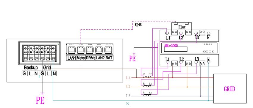
Introduction                   Your Smart Energy

     Introduction

1.1 System Introduction
AlphaESS Storion-SMILE5 (incl. SMILE5-BAT and SMILE-INV) can be applied in DC-coupled systems
(mostly new installation), AC-coupled systems (mostly retrofit) and Hybrid-coupled systems (mostly
retrofit, and PV capacity-increase), as the following schemes show:

                           Figure 1 DC - Coupled Storage System – Scheme

                           Figure 2 AC - Coupled Storage System – Scheme

___________________________________________________________________
                                        Alpha ESS Co., Ltd.
                                                                                           Page 5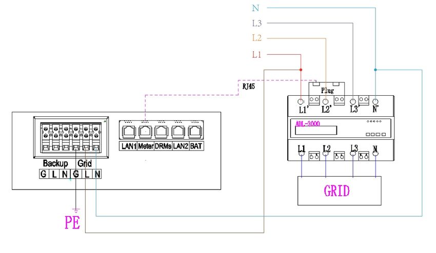
Your Smart Energy                              Introduction

                              Figure 3 Hybrid - Coupled Storage System – Scheme

      CAUTION:
  For the AC-/ Hybrid-coupled system, unlike DC, two power meters are to be mounted.
  SMILE5 cannot be used in pure off-grid systems!

  1.2 Safety Introduction
  1.2.1       Manual keeping
  This manual contains important information about operating the system. Before operating, please read
  it very carefully.
  The system should be operated in strict accordance with the description in the manual, otherwise it
  can cause damages or loss to equipment, personnel and property.
  This manual should be kept carefully for maintenance and reparation.

  1.2.2       Operator Requirements
  The operators should get a professional qualification, or trained.
  The operators should be familiar with the whole storage system, including compositions and working
  principles of the system.
  The operators should be familiar with the Product Instruction.
  While maintaining, the maintainer is not allowed to operate any equipment until all the equipment has
  been turned off and fully discharged.

  1.2.3       Protection of Warning Sign
  The warning signs contain important information for the system to operate safely, and it is strictly
  prohibited to torn or damage them. Ensure that the warning signs are always read-able and correct
  placed. The signs must be replaced immediately when damaged.

  ___________________________________________________________________
                                             Alpha ESS Co., Ltd.
  Page 6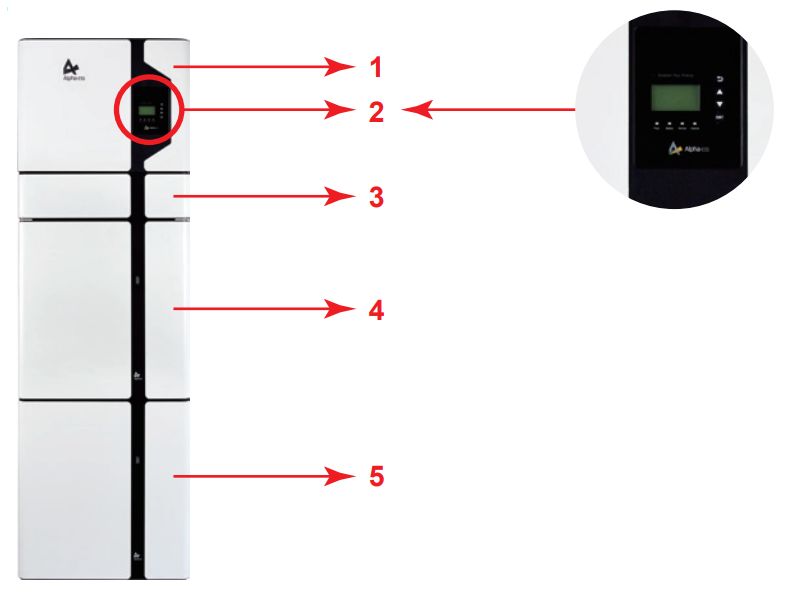
Introduction                    Your Smart Energy

                    This sign indicates a hazardous situation which, if not avoided, could result in
                    death or serious injury!

                    This sign shows danger of high voltage and electric shock!

                    The Storion SMILE5 must not be touched or put into service until 5 minutes after
                    it has been switched off or disconnected to prevent an electric shock or injury.

                    This sign shows danger of hot surface!

                    Refer to the operating instructions.

1.2.4        Setting of Warning Sign for Safety
During instruction, maintenance and repair, follow the instructions below to prevent non-specialist
personnel from causing misuse or accident:
        •   Obvious signs should be placed at front switch and rear-level switch to prevent accidents
            caused by false switching.
        •   Warning signs or tapes should be set near operating areas.
        •   The system must be reinstalled after maintenance or operation.

1.2.5        Measuring Equipment
For ensuring the electrical parameters to match requirements, related measuring equipment are
required when the system is being connected or tested.
Ensure that the connection and use matched specification to prevent electric arcs or shocks.

1.2.6        Moisture Protection
It is very likely that moisture may cause damages to the system.
Repair or maintaining activities in wet weather should be avoided or limited.

1.2.7        Operation After Power Failure
The battery system is part of the energy storage system and stores life-threatening high voltage even
when the DC side is switched off. Touching the battery outlets is strictly prohibited. The inverter can
keep a life-threatening voltage even after disconnecting it from the DC and / or AC side. Therefore, for
safety reasons, it must be tested with a properly calibrated voltage tester before an installer works on
the equipment..

___________________________________________________________________
                                           Alpha ESS Co., Ltd.
                                                                                                  Page 7
Your Smart Energy                              Introduction

  1.3 Battery Safety Datasheet
  1.3.1       Hazard Information
  Classification of the hazardous chemical
  Exempt from classification according to Australian WHS regulations.

  Other hazards
  This product is a Lithium Iron Phosphate Battery with certified compliance under the UN
  Recommendations on Transport of Dangerous Goods, Manual of Tests and Criteria, Part III, sub-
  section 38.3. For the battery cell, chemical materials are stored in a hermetically sealed metal case,
  designed to withstand temperatures and pressures encountered during normal use. As a result, during
  normal use, there is no physical danger of ignition or explosion and chemical danger of hazardous
  materials' leakage. However, if exposed to a fire, added mechanical shocks, decomposed, added
  electric stress by misuse, the gas release vent will be operated. The battery cell case will be breached
  at the extreme. Hazardous materials may be released. Moreover, if heated strongly by the surrounding
  fire, acrid or harmful fume may be emitted.

  1.3.2       Safety Datasheet
  For detailed information please refer to the provided battery safety datasheet.

  1.4 General Precautions

           DANGER
   Danger to life due to high voltages of the PV array, battery and electric shock.
   When exposed to sunlight, the PV array generates dangerous DC voltage which will be present in
   the DC conductors and the live components of the inverter. Touching the DC conductors or the live
   components can lead to lethal electric shocks. If you disconnect the DC connectors from the system
   under load, an electric arc may occur leading to electric shock and burns.
        Ø    Do not touch uninsulated cable ends.
        Ø    Do not touch the DC conductors.
        Ø    Do not open the inverter and battery.
        Ø    Do not wipe the system with damp cloth.
        Ø    Have the system installed and commissioned by qualified people with the appropriate
             skills only.
        Ø    Prior to performing any work on the inverter or the battery pack, disconnect the inverter
             from all voltage sources as described in this document.

  ___________________________________________________________________
                                             Alpha ESS Co., Ltd.
  Page 8
Introduction Your Smart Energy
WARNING
Risk of chemical burns from electrolyte or toxic gases.
During standard operation, no electrolyte shall leak from the battery pack and no toxic gases shall
form. Despite careful construction, if the Battery Pack is damaged or a fault occurs, it is possible
that electrolyte may be leaked or toxic gases formed.
Ø Do not install the system in any environment of temperature below -10°C or over 50°C and
in which humidity is over 85%.
Ø Do not touch the system with wet hands.
Ø Do not put any heavy objects on top of the system.
Ø Do not damage the system with sharp objects.
Ø Do not install or operate the system in potentially explosive atmospheres or areas of high
humidity.
Ø Do not mount the inverter and the battery pack in areas containing highly flammable
materials or gases.
Ø If moisture has penetrated the system (e.g. due to a damaged enclosure), do not install or
operate the system.
Ø Do not move the system when it is already connected with battery modules.
Ø Secure the system to prevent tipping with restraining straps in your vehicle.
Ø The transportation of AlphaESS Storion-SMILE5 must be made by the manufacturer or an
instructed personal. These instructions shall be recorded and repeated.
Ø A certified ABC fire extinguisher with minimum capacity of 2kg must be carried along
when transporting.
Ø It is totally prohibited to smoke in the vehicle as well as close to the vehicle when loading
and unloading.
Ø For the exchange of a battery module, please request for new hazardous goods
packaging if needed, pack it and let it be picked up by the suppliers.
Ø In case of contact with electrolyte, rinse the affected areas immediately with water and
consult a doctor without delay.
CAUTION:
Risk of injury through lifting or dropping the system.
The inverter and battery are heavy. There is risk of injury if the inverter or battery is lifted incorrectly
or dropped during transport or when attaching to or removing from the wall.
Ø Lifting and transporting the inverter and battery must be carried out by more than 2
people.
1.5 Parts List
Check the following parts list to ensure it is complete.
AlphaESS delivers a total system separately on site to client, this consists of:
___________________________________________________________________
Alpha ESS Co., Ltd.
Page 9Your Smart Energy Introduction
SMILE5-INV
1x Mounting 10x M6
8x φ8*60 2x M4 Nuts 4x M6 Nuts 1x Mounting Panel
Bracket Gasket
Two AC
1x Meter 1x
Connectors 1x User
2x MC4 (1x SM60A or 1x ADL3000 or 1x Installation
for grid and Manual
ACR10R) Manual
backup
SMILE5-BAT
6xφ8*60 6x M5*10 6x M4*10 2x Mounting Panel
2x Power Cable
6x M6 Gasket 1x User Manual Battery Communication Cable
(1 black, 1 red)
___________________________________________________________________
Alpha ESS Co., Ltd.
Page 10Introduction Your Smart Energy
1.6 System Appearance
Total height about 182 cm
Figure 4 Storion-SMILE5 Delivery Scope
Object Description
1 Hybrid Inverter
2 EMS Display Screen
3 Cable Box (connected to Inverter)
4 SMILE5-BAT (Battery 1)
5 SMILE5-BAT (Battery 2)
___________________________________________________________________
Alpha ESS Co., Ltd.
Page 11Your Smart Energy Introduction
1.6.1 Cable Box Part
Figure 5 Inverter without Cable Box Covers– Front View
Figure 6 Cable Box Part without Covers – Front View
Item Description Item Description
Dry Contact
External Device Control Interface USB USB Debug Communication Port
Relay
INV Inverter Debug Communication DRMS Power Dispatching Port
Meter Meter Communication Port LAN Net Wire Connection Port
External Expansion Port
BMS Battery Communication Port CAN
Or External Dispatching Port
___________________________________________________________________
Alpha ESS Co., Ltd.
Page 12Introduction Your Smart Energy
Figure 7 Cable Box Part without Covers - Bottom View
Figure 8 Cable Box Part without Covers -
left View
Object Description Item Description
PV1, PV2 PV Connector GRID Terminal Board Grid
Battery Connector Terminal Board Backup
BAT +, BAT - BACKUP
Load
1.7 Liability Limitation
Any product damage or property loss caused by the following conditions AlphaESS does not assume
any direct or indirect liability.
• Product modified, design changed or parts replaced without AlphaESS authorization;
• Changes, or attempted repairs and erasing of series number or seals by non AlphaESS
technician;
• System design and installation are not in compliance with standards and regulations;
• Failure to comply with the local safety regulations (VDE for DE, SAA for AU);
• Transport damage (including painting scratch caused by rubbing inside packaging during
shipping). A claim should be made directly to shipping or insurance company in this case
as soon as the container/packaging is unloaded and such damage is identified;
• Failure to follow any/all of the user manual, the installation guide and the maintenance
regulations;
• Improper use or misuse of the device;
• Insufficient ventilation of the device;
• The maintenance procedures relating to the product have not been followed to an
acceptable standard;
• Force majeure (violent or stormy weather, lightning, overvoltage, fire etc.);
• Damages caused by any external factors.
___________________________________________________________________
Alpha ESS Co., Ltd.
Page 13Your Smart Energy Installation
Installation
This Manual introduces the basic steps how to install and set up AlphaESS Storion-SMILE5.
SMILE5-BAT is a sealed component with no access to battery terminals or cell components within the
module.
SMILE5-BAT contains a Bi-pole DC isolator, which conforms to IEC 60947. It has been operated in all
live conductors
NOTE: please pay attention for unpacking the battery, otherwise components could be
damaged.
2.1 Installation Site and Environment
2.1.1 General
This SMILE5 energy storage system is outdoor version and can be installed in an outdoor or an indoor
location.
When SMILE5 systems are installed in a room, SMILE5 must not be hampered by the structure of the
building, the furnishings and equipment of the room.
The Storion SMILE5 is naturally ventilated. The location should therefore be clean, dry and adequately
ventilated. The mounting location must allow free access to the unit for installation and maintenance
purposes, and the system panels must not be blocked.
The following location are not allowed for installation:
• habitable rooms;
• ceiling cavities or wall cavities;
• on roofs that are not specifically considered suitable;
• access / exit areas or under stairs / access walkways;
• where the freezing point can be reached, such as garages, carports or other places as well
as wet rooms (environmental category 2);
• locations with humidity and condensation over 85%;
• places where salty and humid air can penetrate;
• seismic areas - additional security measures are required;
• sites higher than 3000 meters above sea level;
• places with an explosive atmosphere;
• locations with direct sunlight or a large change in the ambient temperature;
• places with flammable materials or gases or an explosive atmosphere.
2.1.2 Restricted Locations
The SMILE5 shall not be installed —
(a) in restricted locations as defined for panels in AS / NZS 3000;
(b) within 600 mm of any heat source, such as hot water unit, gas heater, air conditioning unit or
any other appliance.
(c) within 600 mm of any exit;
(d) within 600 mm of any window or ventilation opening;
(e) within 900 mm of access to 240 Vac connections; and
(f) within 600 mm of side of other device.
___________________________________________________________________
Alpha ESS Co., Ltd.
Page 14Installation Your Smart Energy
A SMILE5 installed in any corridor, hallway, lobby or the like and leading to an emergency exit shall
ensure sufficient clearance for safe egress of at least 1 meter.
The SMILE5 must also not be installed in potentially explosive atmospheres for gas cylinders that are
heavier than air gases and have a vent clamp in accordance with AS / NZS 3000.
2.1.3 Barrier to habitable rooms
To protect against the spread of fire in living spaces where the SMILE5 is mounted or on surfaces of a
wall or structure in living spaces with a SMILE5 on the other side, the wall or structure shall have a
suitable non-combustible barrier. If the mounting surface itself is not made of a suitable non-
combustible material, a non-combustible barrier can be placed between the SMILE5 and the surface
of a wall or structure.
If the SMILE5 is mounted at a wall or at a distance of 300 mm from the wall or structure separating it
from the habitable space, the distances to other structures or objects must be increased. The following
distances must then remain free:
(i) 600 mm beside the SMILE5;
(ii) 1200 mm above the SMILE5; and
(iii) 600 mm before the SMILE5.
If the distance between the Storion SMILE5 and
the ceiling or any object above the system is
less than 1200 mm, the ceiling or structural
surface above the system must be made of non-
combustible material within a radius of 600 mm
around the system.
The SMILE5 must be mounted so that the
highest point is not more than 2.2 m above the
ground or the platform.
Figure 9 Limit Distance of Installation to
Neighboring Objects
2.2 Installation
Figure 10 Unpacking the inverter and battery
Step 1: Remove the battery and inverter from the packaging box.
___________________________________________________________________
Alpha ESS Co., Ltd.
Page 15Your Smart Energy Installation
2.2.1 Battery Installation
Communication
wiring baffle
Figure 11 Battery with Lid off - Front View Figure 12 Battery with Lid off – Side View
Step 2: Open the front cover of the battery and remove the communication wiring
cover (each battery has such a cover on the left and right sides of the case.). Set the
covers aside and close the case.
NOTE: The front cover of the battery should not be opened more than 90°
Battery Cover
Positive Connector
Negative
Connector
Figure 13 Disassembly Diagram of Battery Top Cover
Step 3: If you use more than 1 battery module, they must be interconnected. For all
other battery modules (battery modules 2-6) you will have to remove the top cover
(with 2 batteries you must remove the cover of one battery, with 3 batteries the
covers of 2 batteries, with 4 batteries the covers of 3 batteries etc.) For the new
version battery please connect the power cables directly.
___________________________________________________________________
Alpha ESS Co., Ltd.
Page 16Installation Your Smart Energy
Figure 14 Battery power cable installation diagram
Step 4: Close the battery front cover and connect the power cable at the top, which
are included in the parts list of SMILE5-BAT
M5*10 Screws
Figure 15 Assemble Battery Mounting Panel
Step 5: Assemble the battery mounting panel on the battery.
___________________________________________________________________
Alpha ESS Co., Ltd.
Page 17Your Smart Energy Installation
Debris Baffle, drill φ8, depth about 70 mm
Figure 16 Battery Installation - Drill Holes
Step 6: Position the battery parallel to the wall and use a Φ8mm drill to drill holes at a
depth of about 70mm in the wall for subsequent fixation of the mounting plates.
NOTE: Place a cover (paper, foil, etc.) over the battery while drilling into the wall to
protect it from dust. In addition, at the place of installation, the slope of the ground on a
horizontal plane may not exceed 3°.
M6 Gasket
φ8*60
Figure 17 Battery Installation – Mounting on the Wall
Step 7: Remove the debris baffle and secure the battery to the wall with screws and
___________________________________________________________________
Alpha ESS Co., Ltd.
Page 18Installation Your Smart Energy
gaskets..
Figure 18 Battery Installation – Second Battery Installation
Step 8: To assemble the second (and all other) battery, repeat steps 6 and 7,
respectively.
Figure 19 Inverter Mounting Panel Installation
Step 9: Remove the inverter mounting plate and bracket and connect them using the
M4 nuts as shown above. Check carefully if everything is tight.
___________________________________________________________________
Alpha ESS Co., Ltd.
Page 19Your Smart Energy Installation
M6 Nuts
Figure 20 Inverter Installation - Inverter Mounting Panel
Step 10: Drill the corresponding holes into the wall with a drill and fix the inverter
mounting plate with screws on the wall and with the M6 nuts to the mounting plate of
the battery. The battery assembly is now complete.
2.2.2 Inverter Installation
Step 11: Please make AC cables on site.
Step 12-1: Please follow the AC cable requirements below.
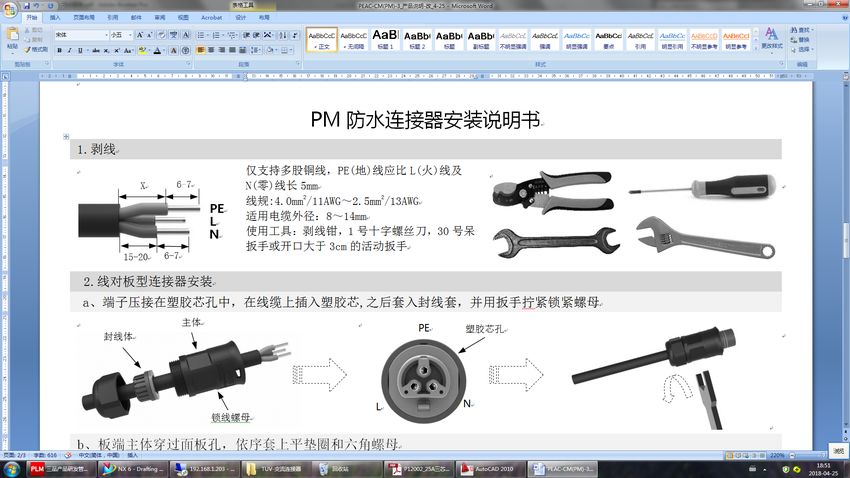
For backup AC cables the stripping method is as following:
Strip the insulation sheath of the three-core AC cable for about.
30mm. Strip L, N and PE cables for 6-7mm respectively.
For grid AC cables the stripping method is as following:
Strip the insulation sheath of the three-core AC cablefor about
35mm. Cut L and N cable for 5mm. Strip L, N and PE cables 6-
7mm for respectively to make sure X-length is 5mm longer than Y-
length of L/ N cable.
Y
___________________________________________________________________
Alpha ESS Co., Ltd.
Page 20Installation Your Smart Energy
Object Description Value
A External diameter 8 mm to 14 mm
B Conductor cross-section 2.5 mm² to 4 mm²
Stripping length of the insulated
C approx.6.5mm
conductors
approx. 30 mm (Backup)
Stripping length of the outer
D approx.30mm (Grid L and N)
sheath of the AC cable
approx.35mm (Grid PE)
Step 11-2: Assemble the AC connector and connect the conductor to the AC
connector
Step 11-3: Ensure that all conductors are securely connected to the AC connector.
Step 11-4: Plug the AC connector into the jack for the AC connection.
a. Parts are equipped with cables
Sealing body
Main part
Lock nut
b. Crimp the wire according to the position shown, tighten the screw torque0.8±
0.1N·m.
PE
Line male
Insert the cables into
the corresponding
Pin holes and tighten
L the screws with the
screwdrivers.
Male N Female
c. The plastic core is screwed into the body
___________________________________________________________________
Alpha ESS Co., Ltd.
Page 21Your Smart Energy Installation
Female
Screw the
body onto
the plastic
core Female
d. Put the sealing body into the main body groove, and then tighten the lock nut to the main body with
a wrench. Torque 2.0±0.3 N·m
Female
Put the sealing
body into the
main body and
lock the lock nut
with a wrench
Figure 21 Cable Box Bottom View, Wiring Connectors
Step 11-5: Connect the Backup and Grid cables in advance according to the connector mode, and
connect them to the Backup and Grid board connectors in turn.
___________________________________________________________________
Alpha ESS Co., Ltd.
Page 22Installation Your Smart Energy
Figure 22 Communication interface of the inverter
Step 12: Take out the communication cable set provided in the accessory parts of one SMILE5-BAT,
cut off one end and crimp a new RJ45 connector. If there are two batteries, you only need to remake
one of battery communication cable on site.
___________________________________________________________________
Alpha ESS Co., Ltd.
Page 23Your Smart Energy Installation
Figure 23 Network Cable Type B
NOTE: The communication cable is in type B, see Figure 23. Leave the power cables
and communication cables hang on the outside. Leave the device aside.
Figure 24 Inverter Installation on the Wall
Step 13: Hang the inverter onto the mounting panels, adjust the entire system and
ensure that the battery and the inverter have been securely hung onto the panels and
brackets.
___________________________________________________________________
Alpha ESS Co., Ltd.
Page 24Installation Your Smart Energy
Figure 25 Wiring the Communication Cable
Step 14: Connect the BAT communication cable of the cable box from Step 12 to the
topmost battery at the right side. Then use the communication cable supplied with
the batteries to connect the batteries to each other via the respective connectors on
the left side. After you have connected all the modules together, close all covers (if
you want to connect further battery modules, you must mount them before closing).
Figure 26 Wiring the Battry Power Cable
Step 15: Connect the power cables of the bottom battery from Step 4 to the side
terminals of the top battery. Make sure that red connects to red and black connects to
black.
___________________________________________________________________
Alpha ESS Co., Ltd.
Page 25Your Smart Energy Installation
Figure 27 Wiring the Power Cable of the Cable Box
Step 16: Connect the power cable of the top battery from Step 4 to the terminals of
the cable box. Make sure that red connects to red and black connects to black.
___________________________________________________________________
Alpha ESS Co., Ltd.
Page 26Installation Your Smart Energy
4*MC4
Figure 28 PV Wiring
Step 17: Close the battery covers and connect the PV-MC4 connectors to the system
(connection on both sides). Also, connect all AC cables, the meter communications
cable METER, and the Ethernet cable LAN. Then close the cable box cover.
The installation is now complete.
NOTE: the RCD unit must be installed. A 100mA RCD device is recommended.
Figure 29 DIP Operation
Step 18: Open the front cover of the last battery and remove the DIP cover. Now set
the DIP switch 2 to "on" mode and close the cover again.
___________________________________________________________________
Alpha ESS Co., Ltd.
Page 27Your Smart Energy Installation
1. If there is only one BAT, the DIP switch of this BAT must be set following:
Battery
DIP 1 DIP 2 DIP 3 DIP 4 DIP Switch
Position.
Battery OFF ON OFF OFF
2. If there are two or more than two BATs, the DIP switch of the BATs must be set
following:
Battery
DIP 1 DIP 2 DIP 3 DIP 4 DIP Switch
Position.
Non-bottom
OFF OFF OFF OFF
battery
Bottom battery OFF ON OFF OFF
NOTE: The DIP setting is only changed on the last battery.
If you connect more than 2 battery modules to the system, please only install the
additional batteries 3-6 on the side of the system. You can connect up to 6 batteries, 2
each mounted on top of each other, to the SMILE 5.
To do this, carry out the individual installation steps as for the first two batteries,
including the DIP setting on the last module.
Figure 30 Increase the Battery Modules
___________________________________________________________________
Alpha ESS Co., Ltd.
Page 28Installation Your Smart Energy
NOTE: Recommended AC circuit breaker rating is 32A.
NOTE: Installer in Australia or New Zealand must install external cuicult breaker or
switch for PV, backup and grid side.
NOTE: In Australia and New Zealand, the neutral of backup and grid circuit should
be externally connected on the neutral bar.
2.2.3 Single Line Diagram
The single line diagrams of DC-, AC- and Hybrid-coupled system are as below:
Figure 31 DC-coupled system
___________________________________________________________________
Alpha ESS Co., Ltd.
Page 29Your Smart Energy Installation
Figure 32 AC-coupled system
Figure 33 Hybrid-coupled system
___________________________________________________________________
Alpha ESS Co., Ltd.
Page 30Installation Your Smart Energy
2.3 Power Meter Wiring
The electricity meter should be mounted and connected at the grid transition point (feed-in point) so
that it can measure the grid reference and feed-in power. Alpha ESS currently provides 4 different
power meter solutions:
Ø ADL-3000: three-/ single-phase meter (with or without CT)
Ø SM60A: single-phase meter
Ø Backup Box: three-/ single-phase meter (Contain off-grid switching and load
management)
Ø ACR10R: Three-phase CT electric meter
Table 1 CT meter ratio and accuracy table
Model CT ratio Accuracy
ADL3000-N/CT & 300A/5A CT 60 0.6 kWh
ADL3000-N/CT & 400A/5A CT 80 0.8 kWh
ADL3000-N/CT & 400A/1A CT 400 4.0 kWh
ACR10R-200A CT 200 2.0 kWh
ACR10R-120A CT 120 1.2 kWh
2.3.1 Meter ADL-3000 (If Applicable)
2.3.1.1 Single-phase in house
ADL-3000 single-phase connection (without CT, without meter plug), if applicable:
LOAD
Figure 34 ADL-3000 single-phase Connect (with CT, without Meter Plug)
NOTE: Connect the power meter (PIN 7, 8) to the meter port of the cable box (PIN 3, 6)
using the RJ45 cable.
___________________________________________________________________
Alpha ESS Co., Ltd.
Page 31Your Smart Energy Installation
ADL-3000 single-phase connection (without CT, with meter plug), if applicable:
LOAD
Figure 35 ADL-3000 single-phase Connect (without CT, with Meter plug)
ADL-3000 single-phase connection (with CT, without meter plug), if applicable:
LOAD
Figure 36 ADL-3000 single-phase Connect (with CT, without Meter plug)
NOTE: Connect the power meter (PIN 7, 8) to the meter port of the cable box (PIN 3, 6)
using the RJ45 cable.
ADL-3000 single-phase connection (with CT, meter plug), if applicable:
LOAD
Figure 37 ADL-3000 single-phase Connect (with CT, with Meter plug)
___________________________________________________________________
Alpha ESS Co., Ltd.
Page 32Installation Your Smart Energy
2.3.1.2 Three-phase in house
ADL-3000 three-phase connection (without CT, without meter plug), if applicable:
Figure 38 ADL-3000 three-phase Connect (without CT, without Meter plug)
NOTE: Connect the power meter (PIN 7, 8) to the meter port of the cable box (PIN 3, 6)
using the RJ45 cable.
.
ADL-3000 three-phase connection (without CT, with meter plug), if applicable:
Figure 39 ADL-3000 three-phase Connect (without CT, with Meter plug)
___________________________________________________________________
Alpha ESS Co., Ltd.
Page 33Your Smart Energy Installation
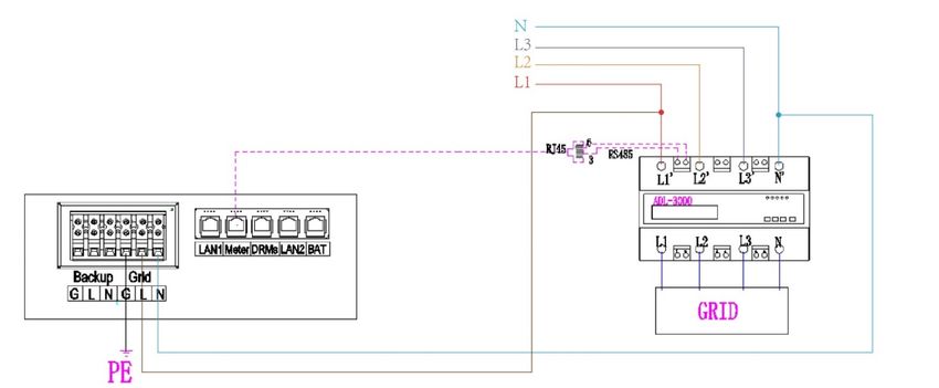
ADL-3000 three-phase connection (with CT, without meter plug), if applicable:
Figure 40 ADL-3000 three-phase Connect (with CT, without Meter plug)
NOTE: Connect the power meter (PIN 7, 8) to the meter port of the cable box (PIN 3, 6)
using the RJ45 cable.
.
ADL-3000 three-phase connection (with CT, with meter plug), if applicable:
Figure 41 ADL-3000 three-phase Connect (with CT, with Meter plug)
NOTE: To connect the current transformer, connect S1 to L1 and S2 to L1’.
For AC-/ Hybrid-system, there are two meter needed:
Option 1: with Meter Plug Option 2: without Meter Plug
Figure 42 Two Meter Connect, with Meter Plug
Figure 43 Two Meter Connect, without
Meter Plug
NOTE: If the ADL3000 meter with CT is used as a grid meter, the direction of arrow in CT
___________________________________________________________________
Alpha ESS Co., Ltd.
Page 34Installation Your Smart Energy
should point away from the grid to the energy storage system.
If the ADL3000 meter with CT is used as a PV meter in AC- or hybrid-coupled system, the
direction of arrow in CT should point away from the PV inverter to the energy storage system.
2.3.2 Meter SM60A (If Applicable)
2.3.2.1 SM60A connect (with meter plug), if applicable:
LOAD
Figure 44 SM60A connect (with meter plug)
2.3.2.2 SM60A connect(without meter plug), if applicable:
LOAD
Figure 45 SM60A connect (without meter plug)
NOTE: Connect the power meter (PIN 5, 6) to the meter port of the cable box (PIN 3, 6)
using the RJ45 cable.
For AC/Hybrid system, there are two meter needed:
Option 1: with Meter Plug Option 2: without Meter Plug
Figure 46 Two Meter Connect, with Meter Plug Figure 47 Two Meter Connect, without Meter
Plug
___________________________________________________________________
Alpha ESS Co., Ltd.
Page 35Your Smart Energy Installation
2.3.3 ACR10R Meter (if applicable)
2.3.3.1 ACR10R single-phase connection
Figure43 ACR10R single-phase connection (if applicable)
2.3.3.2 ACR10R three-phase connection
Figure 44 CR meter three-phase connection (if applicable)
NOTE: Connect the power meter (PIN 21, 22) to the meter port of the cable box (PIN 3, 6)
using the RJ45 cable.
For AC/Hybrid system, there are two meter needed:
___________________________________________________________________
Alpha ESS Co., Ltd.
Page 36Installation Your Smart Energy
without Meter Plug
Figure 48 Two Meter Connect, without Meter Plug
If the ACR10 meter is used as a grid meter, the direction of arrow in CT should point away from the
grid to the energy storage system.
If the ACR10R meter is used as a PV meter in hybrid system, the direction of arrow in CT should point
away from the PV inverter to the energy storage system.
2.3.4 Backup Box (If Applicable)
Backup Box Connect to SMILE5 (single-phase grid in house):
patch cable
COM
patch cable
GRID_L1
LOAD_L1
PV-INV_L1 AC_L1
GRID_L2 BAK_L1 LOAD3 LOAD2 LOAD1
L PV-INV_L2 LOAD_L2
GRID N AC_L2
GRID_L3 RCD
PE BAK_L2
PV-INV_L3 LOAD_L3
AC_L3 L
meter patch cable
GRID_N
齿
for backup box
BAK_L3 N AC
L PV-INV_N PE Storion-S5 侈
LOAD_N PV
PV PV-INV meter ECO-ES5
N
GRID_PE AC_N L SMILE5
PV-INV_PE BAK_N N BACK
Meter Port
PE
patch cable
Bat
DSP_BackupBox
Figure 49 Backup Box Connect to SMILE5 (single phase grid in house)
___________________________________________________________________
Alpha ESS Co., Ltd.
Page 37Your Smart Energy Installation
2.3.5 Meter setting
2.3.5.1 SM60A
There are 3 buttons on the front of the electricity
meter:
1. Down arrow: shift button
2. Up arrow: value adjustion
3. Enter button / Menu button
Step 1: Click the “Enter” button to enter the Step 2: Click the “Enter” button to input the
menu interface. password. The initial password is 0000. Then
click the “Enter” button.
Step 3: You will get into the code interface. Then Step 4: Please set the meter address by using
click the “Shift” button to enter the adress the “Value adjustion” button, the Grid meter (DC,
interface. AC and Hybrid system) address is set to 003,
and the PV meter (AC and Hybrid system)
address is set to 004.
Step 5: Click the “Enter” button to get back to Step 6: Click the “Shift” button to save the
the menu interface. Then click the “Shift” button setting.
5 times to enter the save interface.
___________________________________________________________________
Alpha ESS Co., Ltd.
Page 38Installation Your Smart Energy
2.3.5.2 ADL3000
There are 4 buttons on the front of the electricity
meter:
1. Enter button / Energy button
2. Down arrow / Power button
3. Up arrow / Voltage & current button
4. SET button
Step 1: The initial interface of the meter Step 2: Click the “SET” button to enter the
(normal working mode) is shown above. password interface
Step 3: Click the "Enter" button to enter the Step 4: Click the "Enter" button and the
above interface, and press the up and down password input is completed.
arrow keys to enter the password 0001.
Step 5: Click the “Enter” button again to Step 6: Click the “Enter” button and press the
enter the address interface up and down arrow keys to set the meter
address. The Grid meter (DC, AC and Hybrid
system) address is set to 001, the PV meter
(AC and Hybrid system) address is set to 002.
___________________________________________________________________
Alpha ESS Co., Ltd.
Page 39Your Smart Energy Installation
Step 7: Click the "Enter" button and the Step 8: Click the “SET” button to enter the
address setting is completed. following interface
Step 9: Click the “SET” button again to
enter the save interface
Step 10: Click the “Enter” button to enter the
following interface, press the up and down
arrow keys, and set “no” to “YES” to save the
configuration.
Step 11: Click the "Enter" button and the
setting ends.
2.3.5.3 ACR10R
There are 5 buttons on the meter's front:
1. Enter key
2. Arrow to the right
3. Up arrow
4. SET button
5. FN key (no function)
___________________________________________________________________
Alpha ESS Co., Ltd.
Page 40Installation Your Smart Energy
Step 1: Activate the meter display by pressing Step 2: Use the arrow keys to select the
any key. Then click the "Set" button. "SETUP" menu item and confirm your selection
with the Enter key.
Step 3: Enter the password "0001" and confirm Step 4: Select the menu item "Comm" in the
the entry by pressing the Enter key. settings menu to change to the communication
settings.
Step 5: Set the communication address and communication baud rate in the communication setting
interface. When the meter is used as Grid meter (DC, AC/Hybrid system), the address is set to
“005”. When it is used as the PV meter (AC/Hybrid system), the address is set to “006”. The baud
rate is set to 9600.
___________________________________________________________________
Alpha ESS Co., Ltd.
Page 41Your Smart Energy System Operation
System Operation
3.1 Switch on
When turning on the system, it is very important to follow the order of the following steps to prevent
damage to the system.
WARNING: Please check the installation again before turning on the system.
Step 1: Turn on the external PV switch
Step 2: Turn on the external grid switch.
Step 3: If backup load is applied, turn on the external
Backup switch.
1
NOTE: the Backup switch is only used when a
2
backup load is applied.
Step 4: Open the outer shell of the cable box. Open the
battery switch cover and turn on the battery switch on
the cable box.
Step 5: Press power button on all the batteries until the
indicator lights turn on.
Step 6: Close the battery switch cover and the outer
shell of the cable box.
3.2 Switch off
Step 1: Press the power button on all the batteries, till the lights turn off.
Step 2: Open cable box outer shell, open the battery switch cover and turn off the battery
switch.
Step 3: Turn off the external grid switch.
___________________________________________________________________
Alpha ESS Co., Ltd.
Page 42System Operation Your Smart Energy
Step 4: If backup load is applied, turn off the external backup switch.
Step 5: Turn off the external PV switch on the cable box.
Step 6: Close the battery switch cover and the outer shell of cable box.
More information can be found in SMILE5-BAT user manual.
3.3 Emergency Procedure
When the SMILE5 energy storage system appears to be running abnormally you can turn off the grid
connected main switch directly feeding the BESS and turn off all load switches within the BESS, turn
off the battery switch at the same time. To prevent a potentially fatal personal injury, if you want to
repair or open the machine after the power is switched off please measure the voltage at the input
terminals with a suitably calibrated voltage tester.
Before working on this equipment, please confirm that there is no grid electric supply to the BESS!
The upper cover plate cannot be opened until the DC-link capacitance inside the battery modules
discharges completely about 15 minutes later.
3.3.1 Emergency Handling Plan
1. Disconnect the AC breaker.
2. Check the control power supply. If it is OK, return the power supply to find out the reason.
3. Please record every detail related to the fault, so AlphaESS can analyse and solve the fault. Any
operation of equipment during a fault is strictly forbidden, please contact Alpha as soon as possible.
4. As battery cells contains a little Oxygen inside and all cells have got explosion-proof valves,
explosion hardly happens.
5. When the indicator light on the battery shows a red fault, check the fault type through the
communication protocol, and contact our after-sales service personnel for advice.
3.3.2 Hazards
If the battery pack leaks electrolyte, avoid contact with the leaking liquid or gas. If one is exposed to
the leaked substance, immediately perform the actions described below:
Inhalation: Evacuate the contaminated area, and seek medical attention.
Eye contact: Rinse eyes with running water for 5 minutes, and seek medical attention.
Contact with skin: Wash the affected area thoroughly with soap and water, and seek medical attention.
Ingestion: Induce vomiting and seek medical attention.
3.3.3 Fire
If a fire breaks out in the place where the battery pack is installed, perform the following
countermeasures:
Fire extinguishing media
During normal operation no respirator is required. Burning batteries can not be extinguished with a
regular fire extinguisher, this requires special fire extinguishers such as the Novec 1230, the FM-200
or a dioxin extinguisher. If the fire is not from a battery, normal ABC fire extinguishers can be used for
extinguishing.
___________________________________________________________________
Alpha ESS Co., Ltd.
Page 43Your Smart Energy EMS Introduction and Set up
Fire -fighting instructions
1. If fire occurs when charging batteries, if it is safe to do so, disconnect the battery pack circuit
breaker to shut off the power to charge.
2. If the battery pack is not on fire yet, extinguish the fire before the battery pack catches fire.
3. If the battery pack is on fire, do not try to extinguish but evacuate people immediately.
There may be a possible explosion when batteries are heated above 150°C. When the battery
pack is burning, it leaks poisonous gases. Do not approach.
Effective ways to deal with accidents
Battery in dry environment: Place damaged battery into a segregated place and call local fire
department or service engineer.
Battery in wet environment: Stay out of the water and don’t touch anything if any part of the battery,
inverter, or wiring is submerged.
Do not use a submerged battery again and contact the service engineer.
EMS Introduction and Set up
4.1 Function Description
Figure 50 SMILE5 EMS Interface
Object Name Description
A Red: The inverter is in fault.
Green: The battery is in charging or
B
discharging.
Indicator LED
C Green: The inverter is in normal state.
D Green: The inverter is in communication.
Return Button: Escape from current
E
interface or function.
Button Function
Up button: Move cursor to upside or
F
increase value.
___________________________________________________________________
Alpha ESS Co., Ltd.
Page 44EMS Introduction and Set up Your Smart Energy
Down Button: Move cursor to downside or
G
decrease value.
H ENT Button: Confirm the selection.
Display the information of the inverter in
I LCD Screen
this LCD screen.
4.2 Introduction
This part is suitable for EMS firmware-version 1.01.67 and above.
4.2.1 Main
Main displays the inverter working status and
information, including:
• Power: Current PV power
• Total: Total power generation.
• Battery: Current remaining battery
power (SOC).
• Normal: Current working state of the
equipment, including Standby.
In the Main interface, press ENT key to enter the
menu’s main interface.
Use the up and down key to select a sub-menu,
press the ENT key to enter the selected sub-
menu, press Return key to return to the previous
layer.
4.2.2 Status
Status menu contains five sub-menus: Solar,
Battery, Grid, UPS and Comm .These display the
relevant information about the current physical or
communication interface respectively.
Grid interface displays the real-time information
on the ultility grid side:
voltage U, current I, frequency F, PInv, PMeterAC,
PMeterDC.
___________________________________________________________________
Alpha ESS Co., Ltd.
Page 45Your Smart Energy EMS Introduction and Set up
Solar interface displays the real-time information
of PV side: voltage U1, current I1, power P1,
voltage U2, current I2 and power P2.
Battery interface displays the real-time information
of battery side: voltage U, current I, power P,
residual capacity of Battery (SOC), the internal
environmental temperature Temp
UPS interface displays the real-time information in
this mode: voltage U, current I, power P,
frequency F
Communication interface displays the real-time
communication situation of BMS, Net, MeterGrid
and MeterDC.
4.2.3 History
History menu contains seven sub-menus: Grid
Consumption, INV Gen., BAT Gen., PV Gen.,
Grid Charge, PV Charge, Error Logs
Grid Consumption interface displays today’s or
total load consumption from grid
___________________________________________________________________
Alpha ESS Co., Ltd.
Page 46EMS Introduction and Set up Your Smart Energy
INV Gen. interface displays today’s or total
electricity quantity generated from SMILE5-INV.
Bat Gen. interface displays today’s or total
electricity quantity discharged from the battery.
PV Gen. interface displays today’s or total
electricity quantity generated from the PV-panels.
Grid Charge interface displays today’s or total
electricity quantity battery charging from the grid.
PV Charge interface displays today’s or total
electricity quantity battery charging from the PV-
panels.
Error Logs interface displays the 10 latest fault
records of this device, including the name of the
fault and time of error.
___________________________________________________________________
Alpha ESS Co., Ltd.
Page 47Your Smart Energy EMS Introduction and Set up
Make sure all numbers in the information menu
are correct.
4.2.4 Setting
4.2.4.1 General Setting
Step 1: Click setting and enter the password.
The installation's password is a four-digits
password: 1111, after four-digits password was
correctly input, you can enter into the main
Setting interface (administrator permissions).
Step 2: Click Function to enter function setting. Step 3: Click Solar to set the Solar relevant
information.
Step 4: Set on-grid capacity, storage capacity Step 5: Click the Battery Function and check
and number of PV strings (MPPT number). battery type SMILE5-BAT.
Step 6: Check SOC Calibration function set No. Step 7: Check the Battery Ready function set
No. If you only use the inverter without battery,
___________________________________________________________________
Alpha ESS Co., Ltd.
Page 48EMS Introduction and Set up Your Smart Energy
please set it Yes.
Step 8: Click the Grid Function to set up Step 9: Set the Max. Feed in rate value.
relevant parameters about the grid
Step 10: Click Function-System Mode to set Step 11: Click the mode then set up work
system mode: DC, AC, Hybrid. mode.(self-use or force time charge)
Step 12: If you want to use force charge, sett Step 13: Set the charge and discharge time.
Enable here.
Step 14: Set the UPS Reserve SOC, it means Step 15: Click Safety in the setting menu. Set
how much battery energy to keep for UPS safety standard.
function.
AS4777 for Australia, ARN4105 for Germany,
CEI0_21 for Italy, G83_2 for Great Britain,
NRS097_2_1 for South Africa, RD1699 for
Spain, VDE0216 for 60Hz countries.
___________________________________________________________________
Alpha ESS Co., Ltd.
Page 49Your Smart Energy EMS Introduction and Set up
Step 16: If you use CT meter, please set CT Step 17: If you use UPS function, please set the
meter enable and the relevant ration mute as YES in UPS System interface and the
relevant Frequency.
Step 18: Click System in the setting menu. Click Step19: Click Ethernet to set the IP address.
Date &Time and set up the date and time. DHCP mode means that setup IP address is set
up automatically.
If you want to set up the IP address manually,
please choose manual mode.
NOTE: It is needed to set the following 3 parameters for manual mode:
IP Address: IP address;
Subnet Mask: Subnet mask;
Default Gateway: Default gateway;
Automatic display one parameter:
MAC Address: display MAC Address.
Figure 51 Date&Time Setting Interface Figure 52 Date&Time Setting Interface
Step 20: Click Language to set language Step 21: Make sure all the following number is
correct.
4.2.4.2 Additional Function Setting
If you use Backup box, please set as below:
Step 1: Click Enable to set yes. Step 2: Set the priority of the load,
___________________________________________________________________
Alpha ESS Co., Ltd.
Page 50EMS Introduction and Set up Your Smart Energy
L1>L2>L3
If external device will dispatch the system, please set as following steps:
Step 1: Please go to the function menu, choose Step 2: Please set Modbus enable as yes.
“ModBus” and press enter.
If you use cascading function please set as following steps:
Step 1: Please go to the function menu, choose Step 2: Please choose “Select” as “Yes” and
“Parallel” and press enter. press enter.
Step 3: Please choose “Phase” as L1 (master) Step 4: Please choose “Mode” as “Parallel
and press enter. mode” and press enter.
Step 5: please repeat Step 1 to 4 to set the other device as L2 (slave) L3 (slave).
___________________________________________________________________
Alpha ESS Co., Ltd.
Page 51Your Smart Energy Online Monitoring
Online Monitoring
Installers who haven't registered yet need to click “Register” to visit the registration page. Please refer
to “AlphaCloud Online Monitoring Webserver Installers User Manual”, which you can get from
AlphaESS sales and get your personal license number from relevant AlphaESS sales.
Log in to your installer account and choose
Storage System Maintenance> "Install new
system" to register a new system at Alpha
ESS.
___________________________________________________________________
Alpha ESS Co., Ltd.
Page 52Online Monitoring Your Smart Energy
Enter the system S/N, check code, license, installation date, client name, contact number, contact
address, and click the save button. The red * marks required information for this process. Click the
Browse button to select an attachment you want to add.
5.1 System Setup in Monitoring
Some of the system settings must be carried in the installer monitoring. To do this, follow the steps
below:
Step 1: Please login in the installer account, click the list of storage systems and enter the SN.
5.1.1 Basic Information
Step 2: After selecting the correct system, enter System Setup interface. Enter in the "Basic
Information" and input below information:
- Address,
- Zip code,
- Contact name,
- E-Mail address,
- Currencies and
- Telephone number.
NOTE: Do not forget to click “Save” button!
5.1.1 Other Information
Step 3: select the "Other Information" submenu and set the following parameter:
- Time zone
- Data upload frequency: SMILE5 has second level data, you can choose it as 10s data if you wish.
___________________________________________________________________
Alpha ESS Co., Ltd.
Page 53Your Smart Energy Routine Maintenance
Routine Maintenance
6.1 Maintenance Plan
Ø Check if wire connections are loose.
Ø Check if cables are aged/damaged.
Ø Check if cable insulating ribbon drops.
Ø Check if cable terminal screw loose, any overheat sign.
Ø Check if ground connection is well.
6.1.1 Operating Environment
(Every half year)
Carefully observe whether the battery system equipment is ineffective or damaged;
When the system is running, listen to any part of the system for abnormal noise;
Check whether the voltage, temperature and other parameters of the battery and other equipment
parameters are normal during system operation;
6.1.2 Equipment Cleaning
(Every six months to one year, depending on the site environment and dust content, etc.)
Ensure that the ground is clean and tidy, keep the maintenance access route unblocked, and ensure
that the warning and guiding signs are clear and intact.
Monitor the temperature of the battery module and clean the battery module if necessary.
6.1.3 Cable, Terminal and Equipment Inspection
(Every six months to one year)
Ø Check if the cable connections are loose.
Ø Check whether the cables are aged / damaged.
Ø Check whether the cable tie of the cable has fallen off.
Ø Check if the cable terminal screws are loose and the terminal position has any signs of
overheating.
Ø Check whether the management system of the system equipment, monitoring system and
other related equipment are invalid or damaged.
Ø Check that the grounding of the equipment is good and the grounding resistance is less than
10 ohms.
6.2 Notes
After the equipment are out of operation, the following notes should be paid attention to while
maintaining:
Ø Related safety standards and specifications should be followed in operation and
maintenance.
Ø Disconnect all the electrical connections so that the equipment would not be powered on.
Ø Wait at least 5 minutes after disconnection, so that the residual voltage of the capacitors
drops to a safe voltage. Use a multimeter to make sure that the equipment is completely
discharged.
___________________________________________________________________
Alpha ESS Co., Ltd.
Page 54You can also read