SeapiX Installation Manual - iXblue
←
→
Page content transcription
If your browser does not render page correctly, please read the page content below
SeapiX Installation Manual
SeapiX – Installation Manual

Revision History

 Edition    Date     Comments

 A         01/2020   Creation

                                SSD-C-1306 Ed. A – 01/2020                             2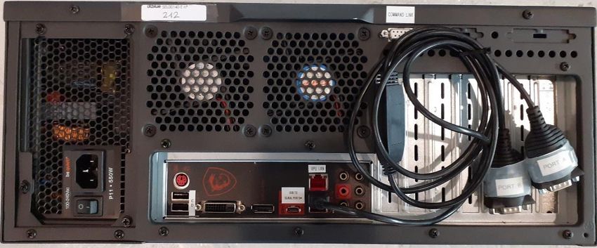
SeapiX – Installation Manual

Copyright
             All rights reserved. No part of this manual may be reproduced or transmitted, in any form or
             by any means, whether electronic, printed manual or otherwise, including but not limited to
             photocopying, recording or information storage and retrieval systems, for any purpose
             without prior written permission of iXblue.

Disclaimer
             iXblue specifically disclaims all warranties, either expressed or implied, included but not
             limited to implied warranties of merchantability and fitness for a particular purpose with
             respect to this product and documentation. iXblue reserves the right to revise or make
             changes or improvments to this product or documentation at any time without notify any
             person of such revision or improvments.
             In no event shall iXblue be liable for any consequential or incidental damages, including but
             not limited to loss of business profits or any commercial damages, arising out of the use of
             this product.

Trademarks
             Microsoft, MS-DOS and Windows are registered trademarks of Microsoft Corporation.
             Intel and Pentium are registered trademarks and Celeron is a trademark of Intel
             Corporation.
             Delph is a registered trademark of ELICS.

                                                           SSD-C-1306 Ed. A – 01/2020                             3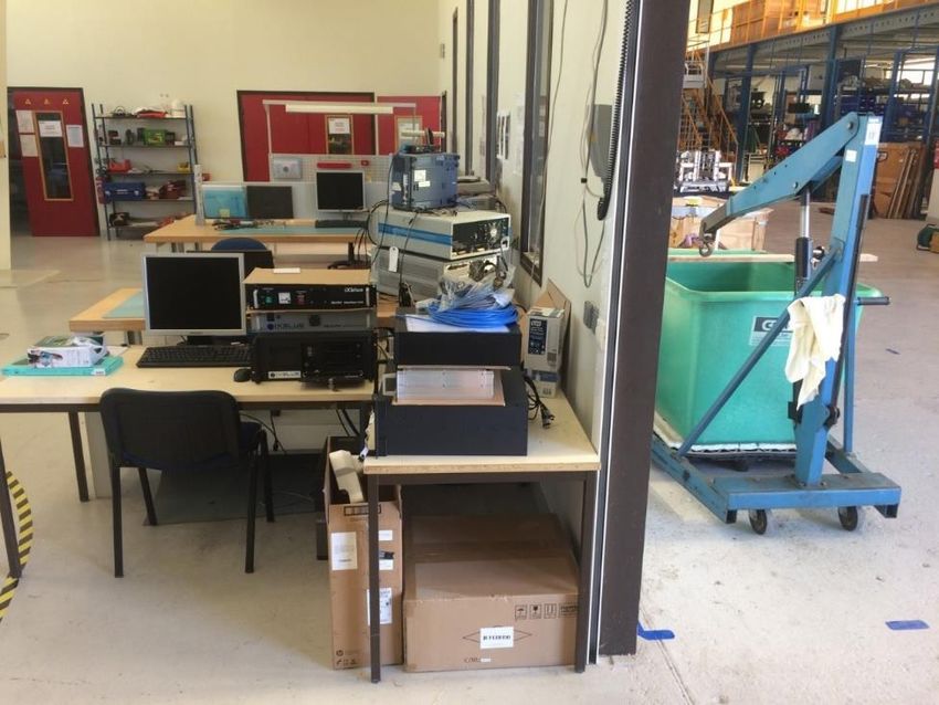
SeapiX – Installation Manual

Warranty
           iXblue provides a standard warranty of two (2) years covering this product against any
           defect in materials or manufacture. The warranty starts from the date of the product received
           at the customer’s location. In the event that a defect in materials or manufacture becomes
           obvious during the stipulated warranty period, iXblue will undertake, at its sole discretion,
           either to repair the defective product, bearing the cost of all parts and labor, or to replace it
           with an identical product.
           In order to avail itself of this warranty, Customer must notify iXblue of the defect before
           expiry of the warranty period and take all steps necessary to enable iXblue to proceed.
           Customer shall be responsible for the packaging and the shipment of the defective product
           to the repair center notified by iXblue, the cost of such shipment being borne by Customer.
           iXblue agrees to bear the cost of return freight, based on CPT (Cost Paid To) Customer’s
           airport location, import tax-free.
           This warranty shall not be construed as covering defects, malfunctions or damages caused
           by improper use or inadequate maintenance of the product. Under no circumstances shall
           iXblue be due to provide repair or replacement under this warranty in order a) to repair
           damage caused by work done by any person not representing iXblue for the installation,
           repair or maintenance of the product ; b) to repair damage caused by improper use or
           connection to incompatible equipment, and specifically, the opening of the housing of the
           equipment under warranty shall cause the warranty to be automatically cancelled ; c) to
           maintain any product that has been modified or integrated into a larger configuration, if such
           modification or integration increases the duration or difficulty of the maintenance of said
           product ; d) the operating defect is caused by an intervention or as a result of a modification
           that was performed without iXblue prior consent ; e) the failure was caused by normal
           deterioration (wear and tear) of the product, or by negligence or by improper care on the
           part of the Customer.
           This warranty covers the product hereunder and is provided by iXblue in place of all and
           any other warranty whether expressed or implied. iXblue does not guarantee the suitability
           of the product under warranty for sale or any specific use. iXblue’s liability is limited to the
           repair or replacement of defective products, this being the sole remedy open to Customer
           in the event the warranty becomes applicable. iXblue cannot be held liable for indirect,
           special, subsequent or consequential damage, irrespective of whether iXblue has or has
           not received prior notification of the risk of occurrence of such damage. The repair,
           replacement or re-performance of parts of defective product shall not cause the warranty
           period mentioned above to be extended, to the exception of the said replaced, repaired or
           re-performed parts for which a 3 month warranty period is granted from shipment to the
           Customer of the replaced or repaired product part.

                                                        SSD-C-1306 Ed. A – 01/2020                             4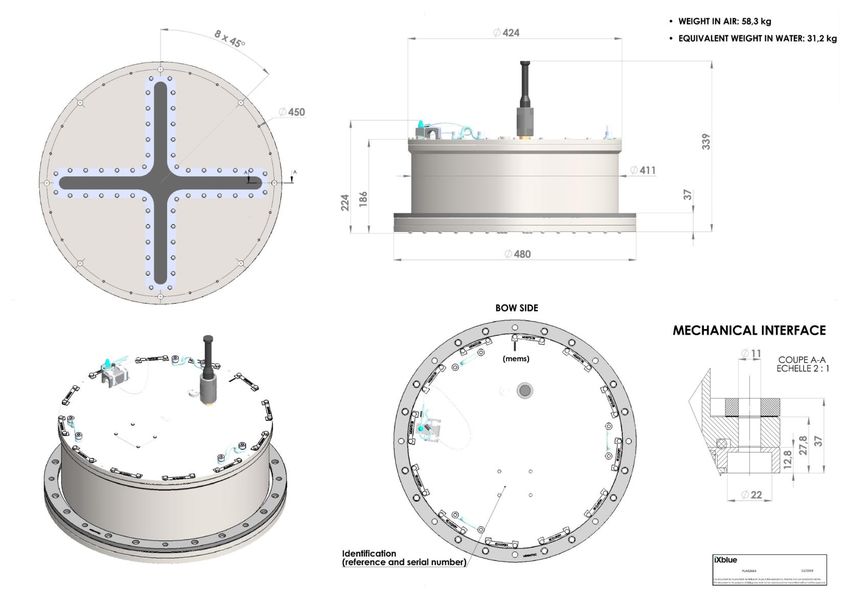
SeapiX – Installation Manual

Software License Agreement
                    PLEASE READ THIS SOFTWARE LICENSE AGREEMENT CAREFULLY BEFORE
                    INSTALLING OR USING THE SOFTWARE.

                    BY CLICKING ON THE "ACCEPT" BUTTON, INSTALLING THE SOFTWARE, OR USING
                    THE SOFTWARE, YOU ARE CONSENTING TO BE BOUND BY THIS AGREEMENT. IF
                    YOU DO NOT AGREE TO ALL OF THE TERMS OF THIS AGREEMENT, CLICK THE "DO
                    NOT ACCEPT" BUTTON AND THE INSTALLATION PROCESS WILL NOT CONTINUE,
                    RETURN THE PRODUCT TO THE PLACE OF PURCHASE FOR A FULL REFUND.
 Grant of license   iXblue grants you a non-exclusive and non-transferable license to use the enclosed iXblue
                    software in the manner provided below:

                    • the number of software users depends on the licenses agreed by iXblue. The user is
                       able to connect with a security key provided by iXblue for use on a single computer;

                    • you may couple multiple iXblue licenses on a single computer;
                    • you may make up to two (2) copies of the software for archival or backup purposes,
                       provided that you reproduce proprietary notices.
    Restrictions
                    • You shall not share by any means, other than by agreement with iXblue, the software
                       licenses between multiple computers.

                    • You shall not copy the software except as set forth in the section above. Any copy of the
                       software that you make must contain the same copyright and other proprietary notices
                       that appear on or in the software.

                    • You shall not modify, adapt or translate the software. You shall not reverse engineer,
                       decompile, disassemble or otherwise attempt to modify or discover the source code of
                       the software.

                    • You shall not install, neither operate the software on virtual machines.
                    • You shall not, rent, lease, sublicense, assign or transfer your rights in the software
                       without prior written authorization from iXblue.
       Copyright    The software (including any images, animations and text incorporated into the software) is
                    owned by iXblue and protected by copyright laws and international treaty provisions
                    applicable.

 Maintenance /      iXblue offers software maintenance during the warranty period. This maintenance includes
  Data update
                    the delivery of minor documentary and software licenses. The major or intermediary updates
                    are not included and shall be dealt with in a separate agreement. If the software supplied
                    under license is an updated version, the licensee will only be allowed to use the software in
                    order to replace versions of the same software previously and duly acquired under license.

      Extended      Extended Maintenance Agreements – E.M.A. – may be purchased to extend the product
   Maintenance
                    maintenance after the warranty period. An E.M.A. shall be applied to every software license
                    that will be maintained and upgraded.

                                                               SSD-C-1306 Ed. A – 01/2020                             5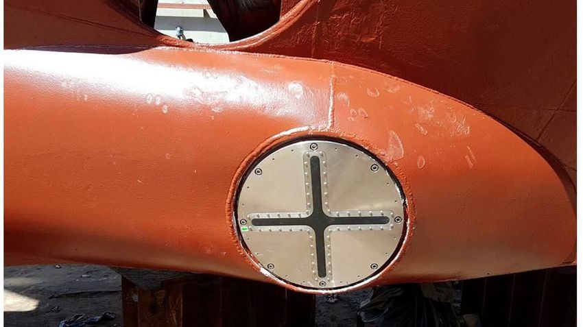
SeapiX – Installation Manual

Technical support    Technical support is available free of charge during the warranty period:

                     • On iXblue website: http://www.ixblue.com/
                     • By dedicated e-mail box: support@ixblue.com
                     • 24/7 hotline: +33 1 30 08 98 98 (EMEA-LATAM), +1 617 861 4589 (NORAM), +65 6747
                        7027 (APAC)

             Price   The price comprises the main product together with accessories: grant of license and
                     accrued expenses (as referred to in the order, contract, or in the manufacturer or supplier
                     price list).

                     The user license is considered to be granted when iXblue acknowledges reception of the
                     whole price paid by the Buyer. Payment is made by means of a secure electronic payment
                     system or by any other means authorized by iXblue.

                     iXblue will notify reception of payment by electronic mail.

     Termination     In case of non-payment and/or non-respect of the present terms, all rights of the license
                     and the use of software will be terminated, without prejudice to any legal action iXblue may
                     carry out against the defaulting party.

                     The Buyer will be obliged, at its own expense and risk, to return to iXblue all copies of the
                     software under license in its possession together with physical protection keys, or to confirm
                     in writing that all software copies under license in its possession have been destroyed.

                     iXblue reserves the right to proceed to all the necessary verifications in order to be assured
                     of the buyer’s observance of the aforementioned conditions.

   Applicable law    This license agreement is governed by the laws of France. Both parties will do their utmost
and Settlement of
          disputes   to bring an end to disputes relative to the interpretation and/or the execution of this
                     document by settling an amicable agreement between their respective management. If an
                     amicable agreement has not been reached within three months, the dispute will be
                     submitted to the jurisdiction of the competent courts of Paris.

                                                                SSD-C-1306 Ed. A – 01/2020                             6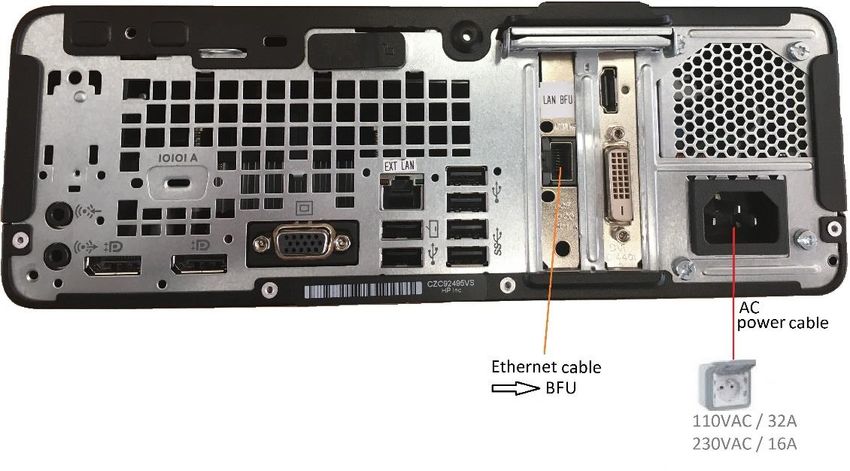
SeapiX – Installation Manual

Limited Warranty
Warranty period    iXblue guarantees that the software will perform substantially in accordance with the
                   accompanying written materials for a period of two (2) years from the date of shipment.

      Customer     iXblue’s entire liability and your exclusive remedy shall be, at iXblue’s option, repair or
      Remedies
                   replacement of the software that does not meet iXblue’s Limited Warranty. Warranty service
                   is F.O.B. iXblue France. All shipping and insurance costs to iXblue are paid for by the Buyer;
                   shipping and insurance costs returning to the Buyer will be paid for by iXblue.

                   On-site Customer Service and Warranty Repair may be provided by iXblue, at its own
                   discretion. Travel and accommodation (including travel hours, transportation, lodging and
                   meals) will be charged by iXblue to the Buyer at cost plus ten (10) per cent. However, actual
                   labor hours to provide this service or repair will be free of charge to the Buyer. This Limited
                   Warranty is void if failure of the software or hardware has resulted from accident, abuse, or
                   misapplication. Any replacement software or hardware will be guaranteed for the remainder
                   of the original warranty period or thirty (30) days, whichever is longer.

    Limitations    iXblue makes no other warranties than the above limited warranties. iXblue makes no
                   warranties, expressed, implied, statutory, or in any communication with you, and iXblue
                   specifically disclaims any implied warranty of merchantability or fitness for a particular
                   purpose. iXblue does not warrant that the operation of the program will be uninterrupted or
                   error free. The Buyer agrees that the responsibility, based on contract or tort law, or the
                   responsibility related to the warranty, shall not exceed the price paid for the acquisition of
                   the product.

       Liability   iXblue’s liability is excluded in case of misuse of the software or any use in contradiction
                   with iXblue’s instructions. This application program is only to be used in order to help
                   optimize fishing and shall not exempt the skipper of his responsibilities in terms of navigation
                   security and respect for law enforcement.

       Dongles     iXblue will not replace lost dongles free of charge, neither offer discounted pricing terms for
                   replacement dongles.

                   iXblue strongly recommends that you insure your iXblue products against loss, theft or
                   damage where applicable.

                   iXblue will propose the replacement of damaged dongles only for a limited fee, provided
                   that the damaged dongle units are returned to iXblue. All shipping and insurance costs are
                   paid for by the buyer.

                                                               SSD-C-1306 Ed. A – 01/2020                             7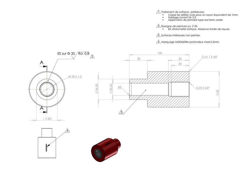
SeapiX – Installation Manual

Export Regulation
                 Export of the products and services described in this document may be subject to different
                 national rules and regulations related to export control.
                 iXblue products and services shall not be exported, re-exported or used in the following
                 countries (including their territorial waters): Cuba, Iraq, Iran, North Korea, Sudan and Syria.
                 The following export control guidelines shall apply as related to French rules and
                 regulations.

   Free export   This product or service can be freely exported.

                                                             SSD-C-1306 Ed. A – 01/2020                             8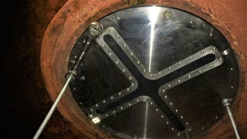
SeapiX – Installation Manual

Manual Overview
         This manual is the Installation Manual for SeapiX manufactured by iXblue. It is intended for
         qualified installing technicians. It must be read and understood prior to using SeapiX. The
         manufacturer shall in no case be held liable for any application or use that does not comply
         with the stipulations in this manual.
         It is divided into several chapters:

         • Part 1: Introduction
         This part contains a general descrition of SeapiX and provides information about the theory
         of operation.

         • Part 2: Technical Characteristics
         This part gives details on mechanical, acoustic and electrical characteristics of the SeapiX
         components.

         • Part 3: SeapiX Pack
         This part details a typical SeapiX pack and its contents; it also gives some
         recommendations.

         • Part 4: Installation Process
         This part details SeapiX installation process.

         • Part 5: SeapiX Commissioning
         This part details how to set up SeapiX for the first time.

         • Part 6: SeapiX Configuration
         This part details which parameters to set prior to using SeapiX.

         • Part 7: Shutdown Procedure
         This part explains how to shut down SeapiX system properly.

         • Part 8: Software Upgrade
         This part explains how to upgrade SeapiX programs.

         • Part 9: Preventive Maintenance
         This part describes the preventive maintenance tasks.

         • Part 10: Troubleshooting
         This part provides a table helping to solve minor problems encoutered while using SeapiX.

         • Part 11: Support through TeamViewer
         This part provides support contacting information through TeamViewer.

         • Appendices
         It contains the detailed drawings and diagrams.

         Warning: SeapiX is NOT a navigation tool. SeapiX is a fishing tool and it must be used as
         such.

         The abbreviations and acronyms used in this manual are listed hereafter.

                                                     SSD-C-1306 Ed. A – 01/2020                             9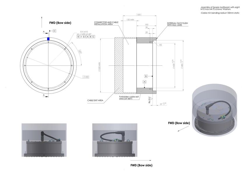
SeapiX – Installation Manual

Abbreviations and Acronyms
          BFU    Beam Former Processor Unit

          CSV    Plain text format file

          ETA    Estimated Time of Arrival

          FEBL   Tool showing the Range Bearing Line

          GUI    Graphical Interface Unit

          ITU    Interface Unit

          GNSS   Global Navigation Satellite System (including GPS, ...)

          MRU    Motion Reference Unit

          RX     Reception

          SAT    Sonar Axial Tiltable mode

          SATA   Data transfer format

          SAU    Sonar Antenna Unit

          SAV    Sonar Axial Volumetric mode

          SED    Single Echo Detection

          SLI    Sonar Lateral Imaging mode

          STT    Sonar Transverse Tiltable mode

          STV    Sonar Transverse Vertical mode

          SV     Scattered Volume; in acoustics, fish shoal measurement mode (in dB)

          TS     Target Strength; in acoustics, single fish measurement mode (in dB)

          TX     Transmission

          VPU    Viewer Processor Unit

                                              SSD-C-1306 Ed. A – 01/2020                           10
SeapiX – Installation Manual
Text Usage
Bold Bold text is used for items you must select or click in the software.
It is also used for the field names used into the dialog box.
Courier Text in this font denotes text or characters that you should enter
from the keyboard, the proper names of disk Drives, paths,
directories, programs, functions, filenames and extensions.
Italic Italic text is the result of an action in the procedures. It is also
used for referencing to other document titles.
Icons
The Note icon indicates that the following information is of particular interest and should be
read with care.
Important
The Important mention indicates that the following information should be read to forbid or
prevent a product dysfunction or a faulty operation of the equipment.
The Caution icon indicates that the following information should be read to forbid or
prevent product damage.
The Warning icon indicates that possible personal injury or death could result from failure
to follow the provided recommendation.
The Advanced/Expert icon indicates that the described procedure/action is reserved to
advanced level of operation.
SSD-C-1306 Ed. A – 01/2020 11SeapiX – Installation Manual
Table of Contents
1 INTRODUCTION ............................................................................................................ 14
1.1 SEAPIX SYSTEM OVERVIEW.......................................................................................................14
1.2 SEAPIX PRINCIPLE ....................................................................................................................15
1.2.1 Downward-Looking Swath .................................................................................................16
1.2.2 Forward-Looking Swath .....................................................................................................16
1.2.3 Side-Looking Swath ...........................................................................................................16
2 TECHNICAL CHARACTERISTICS .................................................................................... 17
2.1 SEAPIX-F .................................................................................................................................17
2.2 SEAPIX-R .................................................................................................................................18
2.3 SEAPIX-L .................................................................................................................................19
3 SEAPIX PACK ............................................................................................................. 20
3.1 PACK CONTENTS ......................................................................................................................20
3.2 DESCRIPTION OF THE PACK ITEMS .............................................................................................21
4 INSTALLATION PROCESS ............................................................................................. 23
4.1 INSTALLATION CHECKLIST .........................................................................................................24
4.2 CABLING AND WIRING ...............................................................................................................27
4.2.1 Transducer Cable (SAU↔ITU) ..........................................................................................27
4.2.1.1 Bending Radius ..................................................................................................................28
4.2.1.2 Connectors .........................................................................................................................28
4.2.2 Ethernet Cables (ITU↔BFU and BFU↔VPU) ...................................................................30
4.2.3 Control Command Cable (ITU↔BFU) ...............................................................................31
4.3 CHECKING THE SYSTEM BEFORE INSTALLING .............................................................................32
4.4 INSTALLING SEAPIX ANTENNA UNIT (SAU) ................................................................................33
4.4.1 Considering the Slamming .................................................................................................33
4.4.2 Cooling Down the SAU ......................................................................................................33
4.4.3 Corrosion Protection of the SAU ........................................................................................33
4.4.4 Hull-Mounting an SAU Step by Step ..................................................................................34
4.4.4.1 Views of Hull-Mounted Antennas ......................................................................................37
4.4.5 Pole-Mounting an SAU Step by Step .................................................................................39
4.4.5.1 Views of Pole-Mounted Antennas ......................................................................................40
4.5 INSTALLING THE INTERFACE UNIT (ITU) .....................................................................................41
4.6 INSTALLING THE BEAM FORMER UNIT (BFU) ..............................................................................42
4.7 INSTALLING THE VIEWER PROCESSOR UNIT (VPU) .....................................................................43
4.7.1 SeapiX Software installation ..............................................................................................44
4.7.2 SeapiX Software reinstallation ...........................................................................................44
5 SEAPIX COMMISSIONING ............................................................................................. 45
6 SEAPIX CONFIGURATION ............................................................................................. 47
6.1 SETTING THE OFFSETS ..............................................................................................................47
6.1.1 Offset Conventions ............................................................................................................47
6.1.2 Offsets Menu ......................................................................................................................47
6.2 SETTING THE INPUTS .................................................................................................................48
SSD-C-1306 Ed. A – 01/2020 12SeapiX – Installation Manual
6.3 SETTING THE OUTPUTS ............................................................................................................. 53
6.4 CHECKING STATUS THROUGH MAIN CONTROLS.......................................................................... 54
6.5 SOFTWARE VERSION & UNITS ................................................................................................... 55
7 SHUTDOWN PROCEDURE ............................................................................................. 56
8 SOFTWARE UPGRADES ................................................................................................ 57
9 PREVENTIVE MAINTENANCE ......................................................................................... 58
10 TROUBLESHOOTING .................................................................................................... 62
11 SUPPORT THROUGH TEAMVIEWER ............................................................................... 66
11.1 USING TEAMVIEWER ................................................................................................................. 66
11.2 REINSTALLING TEAMVIEWER ..................................................................................................... 68
A MECHANICAL AND ELECTRICAL DRAWINGS ................................................................................ 72
SSD-C-1306 Ed. A – 01/2020 13SeapiX – Installation Manual
1 Introduction
1.1 SeapiX System Overview
SeapiX is a volumetric 3D Sonar dedicated to the fishing industry. It provides a realistic fish
evaluation together with a full ecosystem description. Composed of a dual Mills Cross
multibeam sonar array, this compact system is able to generate one or more scan swaths
along or across a vessel axis. The result is a total three-dimensional coverage of the water
column; it also provides a bathymetric profile of the seabed and the identification of the
sediment type.
SeapiX is connected to the vessel navigation system for real-time geo-referenced data
generation. it is used with SeapiX Surface Software for configuration, control and
visualization of data.
SSD-C-1306 Ed. A – 01/2020 14SeapiX – Installation Manual
1.2 SeapiX Principle
SeapiX is a volumetric multibeam echosounder which can operate:
• downward-looking,
• forward-looking,
• side-looking.
Each multibeam swath is proposed along and across the vessel track (is either “axial” or
“transverse”). Swaths are tiltable to control the biomass all around the vessel. For each
swath, 3 echogram sectors are formed from 1° to 120° beam aperture.
On board a fishery vessel, the skipper watches the shoal behavior and steers the vessel to
perform catches.
Warning: SeapiX is NOT a navigation tool. SeapiX is a fishing tool and it must be
used as such.
SSD-C-1306 Ed. A – 01/2020 15SeapiX – Installation Manual
1.2.1 DOWNWARD-LOOKING SWATH
Downward-looking swath (axial & transverse)
1.2.2 FORWARD-LOOKING SWATH
Forward-looking swath (axial & transverse)
1.2.3 SIDE-LOOKING SWATH
Side-looking swath (axial & transverse)
Axial swaths correspond to SAT or SAV sonar modes.
Transverse swaths correspond to STT or STV sonar modes.
SSD-C-1306 Ed. A – 01/2020 16SeapiX – Installation Manual
2 Technical Characteristics
Seapix is available in 3 versions:
• SeapiX-F for fishery
• SeapiX-R for fishery research
• SeapiX-L for marine science and fish farming
2.1 SeapiX-F
SeapiX-F is dedicated to the fish industry and is installed on fishery vessels.
SeapiX-F SAU
Applications Fishery
Frequency 150 kHz
Modulation CW and Chirp
Across-track multibeam swath 64 channels, stabilized
Along-track multibeam swath 64 channels, stabilized
Beam stabilization TX + RX, built-in MRU
Beam resolution 1.6° angular / 7.5 cm radial
Triple echograms from all swaths Adjustable from 1° to 120° each
Typical range Biomass 400m, Bathymetry 600 m
Volume resolution 0,6 m3 @100 m
Volume coverage 120° X 120°
Signal processing SV, TS, NORMALIZED
SED fish extraction Up to 200.000 single fish detection
Transmission power 2 kW (4 kW as an option)
Scientific pack (option)
Sonar Antenna Unit (SAU) cable 20 m
SAU weight 61.5 kg
SSD-C-1306 Ed. A – 01/2020 17SeapiX – Installation Manual
2.2 SeapiX-R
SeapiX-R is dedicated to fishery research and is installed on large fishery research vessels.
SeapiX-R SAU
Applications Fishery research
Frequency 150 kHz
Modulation CW and Chirp
Across-track multibeam swath 64 channels, stabilized
Along-track multibeam swath 64 channels, stabilized
Beam stabilization TX + RX, built-in MRU
Beam resolution 1.6° angular / 7.5 cm radial
Triple echograms from all swaths Adjustable from 1° to 120° each
Typical range Biomass 400 m, Bathymetry 600 m
Volume resolution 0,6 m3 @100 m
Volume coverage 120° X 120°
Signal processing SV, TS, NORMALIZED
SED fish extraction Up to 200.000 single fish detection
Transmission power 4 kW
Scientific pack yes
Sonar Antenna Unit (SAU) cable 20 m
SAU weight 61.5 kg
SSD-C-1306 Ed. A – 01/2020 18SeapiX – Installation Manual
2.3 SeapiX-L
SeapiX-L is a mobile research version dedicated to marine Science and fish Farming; it can
be mounted on a pole and used on an “opportunity vessel”.
SeapiX-L SAU
Applications Marine science and fish farming
Frequency 150 kHz
Modulation CW and Chirp
Across-track multibeam swath 64 channels, stabilized
Along-track multibeam swath 64 channels, stabilized
Beam stabilization TX + RX, built-in MRU
Beam resolution 1.6° angular / 7.5 cm radial
Triple echograms from all swaths Adjustable from 1° to 120° each
Typical range Biomass 400m, Bathymetry 600 m
Volume resolution 0,6 m3 @100 m
Volume coverage 120° X 120°
Signal processing SV, TS, NORMALIZED
SED fish extraction Up to 200.000 single fish detection
Transmission power 2 kW (4 kW as an option)
Scientific pack yes
Sonar Antenna Unit (SAU) cable 20 m
SAU weight 24 kg, floating
SSD-C-1306 Ed. A – 01/2020 19SeapiX – Installation Manual
3 SeapiX Pack
3.1 Pack Contents
The shipping pack contains a Packing List detailing all delivered items. This Packing List
has been completed and checked for by iXblue shortly before shipment and should match
the content of the pack that you have received.
CAUTION: PACK NON-CONFORMITY OR DAMAGE
It is recommended to check the content of the pack and all equipment items immediately
after reception. Specifically, you should check that all items referred to in the Packing List
are present and that none has sustained damage.
If you observe any non-conformity or damage, please inform the carrier and iXblue
without delay by certified mail describing in detail the problem encoutered.
Example of a SeapiX Packing List
SSD-C-1306 Ed. A – 01/2020 20SeapiX – Installation Manual
CAUTION: DO NOT LOSE ANY SMALL PACK ITEM
Before disposing of the packaging, carefully check that no small pack item - such as a key
or a dongle – has been left; otherwise, it would prevent the system from working.
If any part is lost at that stage, you will have to order and pay for it.
3.2 Description of the Pack Items
Item Reference Designation
SMI01628 Sonar Antenna Unit (SAU)
for SeapiX-F and SeapiX-R
either
MDI04776 SAU ring (interface plate)
including
-------------------------------------------
SMI04796 Sonar Antenna Unit (SAU)
for SeapiX-L
or
MDI07607 Mounting flange
optional
SMI01632 Interface Unit (ITU)
+ AC power cable
SEL00140 Beam Former Processor Unit (BFU)
+ 2 sets of keys (front door & disk lock-up)
+ USB to RS-232 converter cable
+ AC power cable
SMI02373 Viewer Processor Unit (VPU)
+ AC power cable
SSD-C-1306 Ed. A – 01/2020 21SeapiX – Installation Manual
Wireless QWERTY Keyboard (for VPU)
Wireless Trackball (for VPU)
SCA00162206-A Transducer Cable (20 m)
(former ref: SCA00130)
SME00573 Cable Gland
SCA00132 ITU-BFU Ethernet Cable (30 m)
SCA00131 ITU-BFU Control Command Cable (30 m)
IOP00122 SeapiX VPU Dongle
FCO00212 BFU-VPU Ethernet Cable (10 m)
CE Declaration of Conformity
Certificate of Warranty
Customer Satisfaction Survey
SSD-C-1306 Ed. A – 01/2020 22SeapiX – Installation Manual
4 Installation Process
This chapter explains how to connect the different units together and how to interface with
the vessel ancillaries and servitudes.
Simplified SeapiX architecture
* UPS is recommended to protect electronic devices. The UPS model must have a ‘pure sine’ output. Other output
wave forms are not SeapiX compatible.
SSD-C-1306 Ed. A – 01/2020 23SeapiX – Installation Manual
4.1 Installation Checklist
As part of the Installation process, a checklist must be completed (see next two pages).
CAUTION: INSTALLATION CHECKLIST TO BE DETACHED AND COMPLETED
When setting up your SeapiX, the Installation Checklist must be completely filled in and
sent back to iXblue. This is compulsory.
Otherwise, your SeapiX system will not be covered by iXblue warrantee.
Fill in the Installation Checklist (see next two pages):
• Enter names and references
• Circle the correct answers when there are Y / N (yes or no) proposals
• Complete your answer with photo(s) when there is a camera icon:
• Complete your answer with screenshot(s) when there is a selection icon:
• Check the boxes when the operation (either check or installation) described has been
done
• Make comments, if any
• Enter your ID, date it and sign it.
When the Installation Checklist has been filled in, scan it (both sides).
Gather all your photos and screenshots in a folder, add the scanned checklist, then
compress it all (make a zip file).
Send a mail to ix-support-seapix@ixblue.com:
• Subject: “Installation Checklist / NameOfShip / Date”,
and attach the zip file.
SSD-C-1306 Ed. A – 01/2020 24SeapiX – Installation Manual
Fill in the form. = Make a photo. = Make a screenshot.
Then e-mail it all to ix-support-seapix@ixblue.com
Installation Checklist (page 1/2)
SSD-C-1306 Ed. A – 01/2020 25SeapiX – Installation Manual
Installation Checklist (page 2/2)
SSD-C-1306 Ed. A – 01/2020 26SeapiX – Installation Manual
4.2 Cabling and Wiring
CAUTION: CRITICAL DAMAGE TO SEAPIX IN CASE OF WRONG WIRING
Wiring shall be made by qualified persons. Any error may induce critical damages to the
SeapiX system and/or equipment onboard the vessel.
4.2.1 TRANSDUCER CABLE (SAU↔ITU)
The transducer cable ensures the powering and the synchronization between the SAU and
the ITU, and the data communication between the SAU and the BFU - through the ITU. It
has been designed and built to work in vessel environment and shall be carefully
manipulated and installed to avoid any system malfunction. The following characteristics
and constraints shall be considered.
CAUTION: DAMAGE TO THE TRANSDUCER CABLE IF EXCESSIVE STRESS OR
TENSION OR IF NOT PROPERLY SECURED
No excessive stress or tension shall apply on the transducer cable.
It shall be secured in such a way that it does not get damaged during cruise in rough
conditions.
CAUTION: FOR OPERATIONAL REASONS, NEVER CUT A TRANSDUCER CABLE
When installing a transducer cable within a pipe, it may happen that the pipe is too
narrow, and you could be tempted to cut the cable to facilitate the cable path. Please note
that it is prohibited to cut the cable as it is part of the EMC protection.
If any cable size issue, please contact iXblue Support.
SSD-C-1306 Ed. A – 01/2020 27SeapiX – Installation Manual
4.2.1.1 Bending Radius
4.2.1.2 Connectors
On SAU side, the connector is un/pluggable underwater.
77 mm
54 mm
Transducer connector, SAU side
A fluorescent “CABLE” sticker indicates the way the connector shall be positioned.
SSD-C-1306 Ed. A – 01/2020 28SeapiX – Installation Manual
Before plugging, please follow the cable manufacturer’s recommendations.
1. Grease the connectors with Molykote 44 Medium (or Novagard Versilube G624) before
mating.
A layer of grease corresponding to approximately 1/3 of the socket depth should be
applied to the female connector.
All sockets should be completely sealed, and a transparent layer of grease left visible on
the connector face.
2. After greasing, fully mate the male and female connectors and remove any excess
grease from the connector joint.
On ITU side, the connector’s dimensions shall be considered when the cable is running
through tubes inside the hull.
To plug the cable onto the ITU, please note that the red dot on top of the cable connector
needs to match the red dot on top of the transducer port on the ITU:
Transducer connector, ITU side
SSD-C-1306 Ed. A – 01/2020 29SeapiX – Installation Manual
4.2.2 ETHERNET CABLES (ITU↔BFU AND BFU↔VPU)
Both Ethernet cables (ITU↔BFU and BFU↔VPU) shall be terminated during the installation
as per the following instructions.
Ethernet cable locking system onto the Interface unit (ITU)
SSD-C-1306 Ed. A – 01/2020 30SeapiX – Installation Manual
4.2.3 CONTROL COMMAND CABLE (ITU↔BFU)
ITU↔BFU Control Command cable shall be terminated during the installation as per the
following instructions.
SSD-C-1306 Ed. A – 01/2020 31SeapiX – Installation Manual
4.3 Checking the System before Installing
We advise you to check the system before installing SeapiX on board the vessel. This
operation shall be done in a clean, dust-free and protected room. Please go to next chapters
and run SeapiX Commissioning (chapter 5) and SeapiX Configuration (chapter 6).
If any anomalies, it will be detected during the check. iXblue recommands to perform it with
its Support Service through TeamViewer (see Support through TeamViewer, chapter 11).
In the example below, the SAU is immersed for testing into a (green) water tank.
We suggest test sequences no less than 15mn long.
Typical test bench including a water tank
SSD-C-1306 Ed. A – 01/2020 32SeapiX – Installation Manual
4.4 Installing SeapiX Antenna Unit (SAU)
To help for assembly, refer to SAU drawings from design office appended in Mechanical
and Electrical Drawings:
• For any details about SeapiX-F or SeapiX-R antenna, go to PLA02664 AG.
• For any details about SeapiX-L antenna, go to PLA14711-AA.
4.4.1 CONSIDERING THE SLAMMING
Please note that the SAU must always be fully immersed – whatever the vessel’s motion.
CAUTION: SLAMMING COULD DAMAGE THE ANTENNA (SAU)
The SAU must be installed in a part not exposed to slamming.
There is a risk the SAU could be distorted - which would not be covered by iXblue
warrantee.
If any slamming risk, it is under the installer’s / shipyard’s responsability. Please refer to 4.1
Installation Checklist and the following box to check:
4.4.2 COOLING DOWN THE SAU
Please note that the SAU must always be fully immersed.
CAUTION: DAMAGE TO THE ANTENNA (SAU)
When using SeapiX, as the SAU is cooled down by thermal dissipation on its rear face, it
is mandatory to have the SAU completely immersed all the time and to insure enough
water flow.
There is a risk the SAU electronics could be damaged because of overheating -
which would not be covered by iXblue warrantee.
4.4.3 CORROSION PROTECTION OF THE SAU
SeapiX SAU is made of marine grade stainless steel (SAE 316 L). When immersed, it shall
be protected against corrosion by anodes:
• an anode is positioned on the SAU rear face,
• a witness anode is positioned on the SAU front face, oriented to the back to avoid
turbulences.
CAUTION: SAU CORROSION IF WORN ANODES
The customer must ensure the anode protection efficiency and its maintainance over time.
Lack of protection may result in severe damage to the SAU and would not be
covered by iXblue warranty.
SSD-C-1306 Ed. A – 01/2020 33SeapiX – Installation Manual
Please refer to 4.1 Installation Checklist:
The following boxes must be checked:
Then
See also ANODES table in 9 Preventive Maintenance.
4.4.4 HULL-MOUNTING AN SAU STEP BY STEP
Step Action
Check that the mounting flange has been welded to the boat’s hull to host the SAU.
1.
2. Position the plastic ring on the SAU and screw it:
3. Check the orientation of the SAU: the indicator located on the SAU rear side shall be
pointing towards the bow. There is also a fluorescent arrow on the SAU front face.
.
SSD-C-1306 Ed. A – 01/2020 34SeapiX – Installation Manual
Step Action
4. Pass the transducer cable through the hull. To tighten it and ensure watertightness, use
iXblue-delivered cable gland: refer to plans PLA05712 AA and PLA06149 AA.
Cable gland
Transducer
cable
Caution
The installation of the cable gland and its qualification are under the shipyard/customer
responsability. The cable gland delivered has been designed for steel hull configuration.
5. Connect the transducer cable onto the SAU; screw it completely but without forcing.
Refer to plan 00162207-A and to 4.2.1 Transducer Cable (SAU↔ITU) to have
information on the authorized bending radius and the connectors’ lubrication and
screwing.
6. Clip the cable into the SAU clipping device then attach it with tie-wraps all along the
compartment to prevent excessive movement during operations.
SSD-C-1306 Ed. A – 01/2020 35SeapiX – Installation Manual
7. Fix the SAU onto the ship’s hull, inside the mouting flange: using a flat wrench and an
Allen wrench, screw the eight (8) M10-screws and washers (inox A4-70). The
appropriate torque is 30N.m ± 10%.
Important
The SAU installation can be done in dry dock or by divers.
SSD-C-1306 Ed. A – 01/2020 36SeapiX – Installation Manual
4.4.4.1 Views of Hull-Mounted Antennas
The antenna (SeapiX-F or SeapiX-R SAU) can be installed in different places on a ship’s
hull; it can be side-looking or down-looking.
Here are a few examples of side-looking antennas:
Side keel blister
Side blister
Bulb
SSD-C-1306 Ed. A – 01/2020 37SeapiX – Installation Manual
Here are a few examples of downward-looking antennas:
Side blister
Side keel blister
SSD-C-1306 Ed. A – 01/2020 38SeapiX – Installation Manual
4.4.5 POLE-MOUNTING AN SAU STEP BY STEP
Step Action
1. Position the plastic ring on the SAU and screw it: refer to PLA02664 AG
2. Check the orientation of the SAU: the indicator located on the SAU rear side shall be
pointing towards the bow. There is also a fluorescent arrow on the SAU front face.
3. Connect the transducer cable:
• refer to plan 00162207-A and to 4.2.1 Transducer Cable (SAU↔ITU) to have
information on the authorized bending radius and the connectors’ lubrication.
• Screw it completely without forcing.
4. Using brackets, fix the SAU to the interface.
5. Let the transducer cable run through the pole and attach the interface to the pole.
Steps 4 and 5 are not under iXblue responsability.
SSD-C-1306 Ed. A – 01/2020 39SeapiX – Installation Manual
4.4.5.1 Views of Pole-Mounted Antennas
Examples of pole-mounted SAUs:
SSD-C-1306 Ed. A – 01/2020 40SeapiX – Installation Manual
4.5 Installing the Interface Unit (ITU)
Once connected to the SAU, passed through the hull and tightened by a cable gland, the
transducer cable must be connected to the Interface Unit (ITU).
Location
The ITU is installed either in a dedicated sonar room or into a technical room, fairly close to
the SAU (transducer cable length = 20 m).
CAUTION: CLEARANCE SPACE NEEDED AT THE REAR OF THE ITU
Enough space shall be available at the rear of the ITU for cable connections
The connectors are located at the back of the ITU:
Figure 1 - ITU back face and connections
• The ITU power cable is plugged into a 110VAC or 230VAC electrical outlet.
• The ITU-BFU control command cable - with DE-9 female termination on ITU side - is
connected to the DE-9 male port (labeled COMMAND LINK).
• The ITU-BFU Ethernet cable is connected to the RJ45 port (labeled DATA LINK) – which
is secured by a clipping system.
• The transducer cable from the SAU is connected to the Fischer port
(labeled TRANSDUCER) – both red dots matching upwards.
SSD-C-1306 Ed. A – 01/2020 41SeapiX – Installation Manual
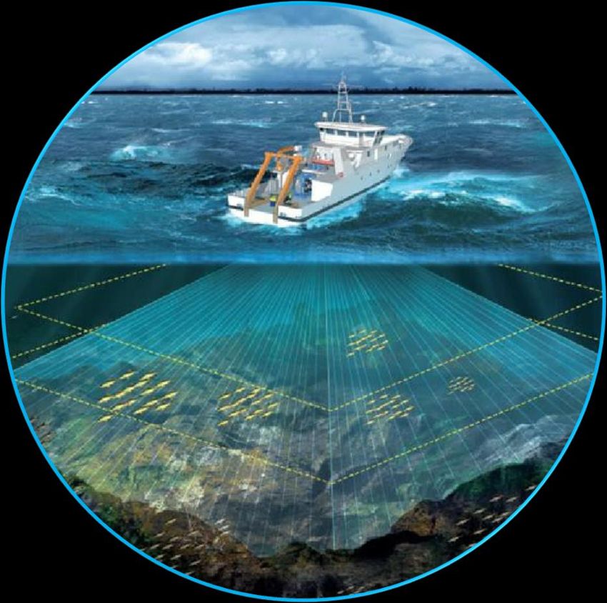
4.6 Installing the Beam Former Unit (BFU)
Once connected to the ITU, the control command and Ethernet cables have been connected
to the Beam Former Unit (BFU).
Location
The BFU is installed on the bridge, often close to the VPU.
The connectors are located at the back of the BFU:
Figure 2 - BFU back face and connections
• The BFU power cable is plugged into a 110VAC or 230VAC electrical outlet.
• The ITU-BFU control command cable - with DE-9 male termination on BFU side - is
connected to the DE-9 female port (labeled CMD LINK).
• The ITU-BFU Ethernet cable is connected to the Ethernet port (labeled LAN ITU).
• The USB-to-RS-232 converter cable - linked to vessel equipment for navigation: e. g.
GPS and Heading sensor - is connected to a USB port (labeled USB TO SERIAL
PORTS).
• The BFU-VPU Ethernet cable is connected to the Ethernet port (labeled LAN VPU).
SSD-C-1306 Ed. A – 01/2020 42SeapiX – Installation Manual
4.7 Installing the Viewer Processor Unit (VPU)
Once connected to the BFU, the Ethernet cable has been connected to the Viewer
Processor unit (VPU).
Location
The VPU is installed on the bridge.
The connectors are located at the back of the VPU:
Figure 3 - VPU back face and connections
• The VPU power cable is plugged into a 110VAC or 230VAC electrical outlet.
• The BFU-VPU Ethernet cable is connected to the RJ45 port (labeled LAN BFU).
• An Ethernet cable to connect to the vessel network is inserted into the RJ45 port (labeled
EXT LAN).
• 2 USB keys for the wireless keyboard and trackball are inserted into 2 USB ports – or
just 1 USB key for both is inserted into either port.
• The SeapiX VPU dongle is inserted into any USB port.
In case the VPU back face would not be easy to reach, please note that ports are
available on its front face.
SSD-C-1306 Ed. A – 01/2020 43SeapiX – Installation Manual
4.7.1 SEAPIX SOFTWARE INSTALLATION
SeapiX software has been factory-installed and set for a specific use (a fishing mode).
If needed to reinstall it – for instance to change settings – go to 4.7.2.
4.7.2 SEAPIX SOFTWARE REINSTALLATION
SeapiX software can be reinstalled on a VPU.
Follow the different steps; then, at some point, the Fishing Mode window will open:
You can select only 1 fishing mode out of 4. Check the fishing mode used on the vessel:
• Pelagic Trawling (PT), or
• Bottom Trawling (BT), or
• Purse Seining (PS), or
• Tuna Seining (TS).
Then click Next > to finish up the software installation.
Important
To get the reinstallation procedure, please contact SeapiX Support.
SSD-C-1306 Ed. A – 01/2020 44SeapiX – Installation Manual
5 SeapiX Commissioning
When SeapiX is used for the first time, follow the step-by-step commissioning process
described below:
Warning: Before proceeding, make sure that the SAU is in the water. Otherwise, severe
damage can occur to SeapiX system.
Step Action
1. Check that the different elements of the SeapiX system have been tested, installed and
connected properly: see 4 Installation Process.
2. Check the power supply voltage and connect the power cords.
3. Check that the ITU is shut down.
4. Power on the BFU.
5. Power on the ITU.
The ITU shall start: on its front face, the blue LED switches on and a peak
consumption (up to 10A) is visible on the current indicator.
6. Power on the VPU. At that stage, SeapiX is ready to be configured.
7. Check that the VPU dongle is inserted.
8. Configure the Offsets and the Inputs / Outputs and check them (see SeapiX
Configuration).
9. From Windows® desktop on the VPU, double-click the SeapiX icon to launch SeapiX
software:
SSD-C-1306 Ed. A – 01/2020 45SeapiX – Installation Manual
10. In the Welcome to SeapiX window which opens, select Administrator as the User -
and a Password, if needed:
Click OK to validate.
11. From the main menu on top of the display, select SeapiX > Service information to
check the connection status.
Note: If any No Connections text shows in red, please check the BFU-to-VPU
connection (see Troubleshooting).
To use SeapiX software, refer to SeapiX Operation Manual, SeapiX Graphical User
Interface (GUI) section.
SSD-C-1306 Ed. A – 01/2020 46SeapiX – Installation Manual
6 SeapiX Configuration
Connect to the web via a browser - Chrome for instance – then type in
192.168.16.9:8989
A program opens which lets you set different controls: start with the Offsets tab, then the
Inputs tab and the Outputs tab. You can then check them all through Main controls tab.
6.1 Setting the Offsets
6.1.1 OFFSET CONVENTIONS
Where, in SeapiX menu, LV1 = XV1, LV2 = XV2 and LV3 = XV3.
6.1.2 OFFSETS MENU
Click OFFSETS to open the following window:
SSD-C-1306 Ed. A – 01/2020 47SeapiX – Installation Manual
All distance values are defined as compared with a Central Reference Point (CRP),
which can be the vessel CoG.
Before filling in the offset values, make sure the SeapiX is not pinging.
• Roll, Pitch and Heading angular values correspond to the installation angles of SeapiX
as compared to the vessel axes.
• LV1, LV2 and LV3 metric values correspond to SeapiX position – the distance between
the SAU central point and the CRP, projected in the vessel frame.
• CRP depth metric value corresponds to the immersion value of the reference point
(positive values increasing as going deeper).
When all settings are done, click OK to validate.
6.2 Setting the Inputs
SeapiX system uses the navigation information from the vessel in order to geo-reference
data. These inputs are connected to the BFU serial ports or Ethernet port:
Input C, Input D Input A, Input B
• Inputs A and B are the serial ports provided.
• Inputs C and D will only be used If a 3rd or a 4th port is needed, after connecting a USB-
to-single-serial port converter.
Inputs A, B, C and D can also be configured as Ethernet ports, if they are not used as serial
ports.
CAUTION: RISK OF SYSTEM CRASH IF WRONG INPUT DATA
The recurrence of navigation data incoming on the BFU must be between 1 Hz (1 value
per second) and 10 Hz (10 values per second).
Outside this range, there is a risk that the system would crash or behave
unexpectedly.
SSD-C-1306 Ed. A – 01/2020 48SeapiX – Installation Manual
Inputs Heading tab lets you set the connections:
Choose a Protocol among:
• $PFEC,GPatt
• $xxHDT
Select on which device the data will be transmitted in the Physical Link drop-down list:
• Serial or Ethernet: data is transmitted via the serial or the Ethernet stream
When Serial physical link is selected :
SSD-C-1306 Ed. A – 01/2020 49SeapiX – Installation Manual
Set the following parameters:
• Parity: from None, Even, or Odd
• Stopbits: from 1.0 or 2.0
• Standard: electric standard for serial output (RS232)
• Baudrate: from 4800 bauds up to 115200 bauds
When Ethernet physical link is selected:
Set the following parameters:
• Transport Layer: TCP Server, TCP Client, UDP, UDP Broadcast.
> “TCP Server” requires a client to establish the connection to the BFU software.
> With “TCP Client”, the address specified is that of the server which sends or receives
data. The BFU software will establish the connection to the server.
> With “UDP”, the address specified is that of the terminal which sends or receives
data. The specific terminal will need to send or listen to data from the BFU software.
> With “UDP Broadcast”, the address specified is a broadcast address limited to the
subnet mask. For example, if the subnet mask is 255.255.0.0 and the system IP is
192.168.16.9, the broadcast address will be 192.168.255.255. All connected
terminals will be able to receive the same data simultaneously by opening the same
port to listen to data.
• IP: IP address of the target (only used in UDP and TCP client)
• Port: port socket number
> You can select any 4-digit number above 1024 as the port number.
Important
To prevent conflicts with other systems or applications, it is important that no identical
numbers are used and that reserved ports are not used.
SSD-C-1306 Ed. A – 01/2020 50SeapiX – Installation Manual
You can manage Misalignments:
• Heading misalignment (-180° / +180°) is the angle between the vessel longitudinal axis
and the heading sensor reference.
• When sensor information is not time-stamped, Latency misalignment is a positive
value used to estimate the exact timing of the information received.
Inputs Attitude tab lets you select a port:
If internal port: nothing to do.
If external port (Input A, B, C, D), fill in the menu which opens (similar as Heading) and
choose a protocol among:
• $PFEC,GPatt
• $PIXSE,ATTITUD
• TSS1
Inputs Heave tab lets you select a port:
If INTERNAL port: nothing to do.
If EXTERNAL port (Input A, B, C, D), fill in the menu which opens (similar as Heading) and
choose a protocol among:
• $PFEC,GPhve
• $PIXSE,HEAVE_
• $xxLIN
• TSS1
• $xxHEV
If port is none, the heave is considered as zero.
SSD-C-1306 Ed. A – 01/2020 51SeapiX – Installation Manual
Inputs Position tab lets you set different connections (Input A, B, C, D):
Choose a protocol among:
• $xxGGA
• $xxRMC
• $PIXSE,POSITI
Inputs UTC tab lets you configure SeapiX according to different modes:
• If None: SeapiX is the master and there is no synchronization of its internal clock.
• If External: SeapiX is a slave and cannot ping unless it receives a TTL signal.
• If RTC: SeapiX is the master and it sets its internal clock through PPS and timeframe
(only $xxZDA protocol is available). Better use it for all applications needing precision
bathy.
SSD-C-1306 Ed. A – 01/2020 52SeapiX – Installation Manual
6.3 Setting the Outputs
The output tabs (Output A to D) let you edit the protocols associated to each one:
The outputs available as a stream from SeapiX are:
• OLEX: protocol read by OLEX software, system for navigation and charting developed
by the norwegian company OLEX AS
• DELPH: XTF protocol read by DELPH software
Caution: If the port you choose has been already configured as an INPUT, there could be
a compatibility issue.
If this happens, choose another output.
SSD-C-1306 Ed. A – 01/2020 53SeapiX – Installation Manual
6.4 Checking Status through Main Controls
Once all settings have been done, click MAIN CONTROL to check the BFU, SAU and
navigation status:
Correct. Problem to fix or just a warning. Critical issue - Not working.
Below are examples without warnings then with warnings:
SSD-C-1306 Ed. A – 01/2020 54SeapiX – Installation Manual
6.5 Software Version & Units
To the right side of the top menu, let you:
When clicking Maintenance, you can check the software version, reset the calibration, or
check the temperature and high voltage hardware status:
When clicking Options, you can change different basic parameters (language, day/night
mode, latitude/longitude notation):
SSD-C-1306 Ed. A – 01/2020 55SeapiX – Installation Manual
7 Shutdown Procedure
If you need to shutdown SeapiX system, follow the step-by-step shutdown process
described below:
Step Action
1. Stop pinging (pressing Start button in SeapiX Software, on the VPU)
2. Shut down the BFU (press the push-button)
Note: At that stage, the ITU & SAU should be shut down too.
3. Check that the ITU is not powering the SAU (the blue LED is off).
4. If any long stop (dry dock, ...) or maintenance operation, switch off the ITU
5. Close SeapiX program.
6. Shut down the VPU.
SSD-C-1306 Ed. A – 01/2020 56SeapiX – Installation Manual
8 Software Upgrades
SeapiX software is continuously improved with bug fixes and new features development.
To make sure you are running the latest software version, visit our Downloads section on
iXblue web site then click Downloads button:
Each release usually consists in:
• An Upgrade Note to explain how to upgrade your SeapiX. Please note that the
procedures might change depending on which version you are currently running.
• A VPU Software Setup File to update the VPU software.
• A BFU Software installation File to update the BFU software.
Download the software upgrade pack then follow the process.
SSD-C-1306 Ed. A – 01/2020 57SeapiX – Installation Manual
9 Preventive Maintenance
The tables below summarize when and how the different items of the SeapiX system shall
be maintained – with typical values.
Important
Please note that harsh environmental conditions can increase the maintenance tasks and
shorten the periodicity.
Caution: Always perform the maintenance tasks requested. Otherwise, it could impact the
SeapiX operation as well as its warranty.
SAU ANTENNA CLEANING
Place Periodicity Time needed Maintenance task
Dry dock Every year 2 hours needed Clean the SAU front face using vinegar-type liquid
and a scraper: remove seaweeds, shells, ...
Caution
While scraping the stainless-steel part, be careful
when approaching the cross - clean it carefully as
the black rubber part is fragile.
ANODES
Place Periodicity Time needed Maintenance task
Dry dock or Every 6 5 mn to check, Inspect the anodes and change them if necessary
Underwater months 2 hours to change Check the witness anode on the SAU front face:
• if its integrity is > 30%: no action.
• if it is worn out (integrity ≤ 30%), change the
witness anode then change the anode located on
the rear side of the SAU:
> Take new anodes from the spare parts.
[witness anode]
[main anode]
> Unscrew each anode.
> Replace it by a new one.
> Screw it again.
SSD-C-1306 Ed. A – 01/2020 58You can also read