Using VUE software to view and organize data - DOC-4399-22 25 Mar 2015
←
→
Page content transcription
If your browser does not render page correctly, please read the page content below

Using VUE software to
view and organize data.

                          DOC-4399-22
                          25 Mar 2015
Summary of Manual

This manual is intended to provide our users with the information they require to use VUE software.
       VEMCO highly recommends that the user fully read the manual before using VUE.

Section 1: Introduction
     Getting to know what VUE software can do for you

Section 2: Getting Started
     How to get VUE ready to begin a study (i.e. before you deploy your receivers)

Section 3: Data Analysis – the basics
     Getting your data ready for analysis

Section 4: Viewing Data
     How to view your data in VUE, including using the filter feature

Section 5: Managing Data
     How to import and export data, and how to view the millisecond timestamps

Section 6: Viewing Events
     To view event information

Section 7: Additional Information
     Helpful information, like how to install the software and set options

Section 8: Frequently Asked Questions
     Things people commonly want to know

Section 9: Appendices

                       Information pertaining to using VUE software with VEMCO
                       receivers is now located in the user manual for that receiver. It is
         NEW           no longer located in this manual. For example, to learn how to
                       communicate with a VR2W, go to the VR2W User Manual.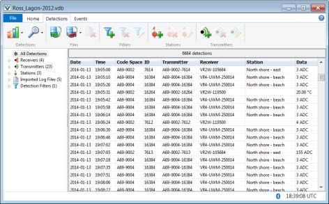
Table Of Contents

1 Introduction ....................................................................... 6
 1.1    Overview of VUE Software ............................................................................................... 6
   1.1.1    What can VUE do? .................................................................................................... 6
   1.1.2    What’s a VRL file? ..................................................................................................... 7
 1.2    The order of things… ........................................................................................................ 8
 1.3    Software Tabs - an overview............................................................................................. 8
   1.3.1    Detections Tab .......................................................................................................... 9
   1.3.2    Events Tab .............................................................................................................. 10
 1.4    Getting Help.................................................................................................................... 10

2 Getting VUE Started ............................................................ 11
 2.1    Open or Create a Database ............................................................................................ 11
 2.2    Set Up Tags.................................................................................................................... 12
   2.2.1    Add Information for a New Sensor Tag .................................................................... 12
   2.2.2    Edit Information for an Existing Sensor Tag ............................................................. 13
 2.3    Set Up Stations ............................................................................................................... 14
   2.3.1    Add a New Station ................................................................................................... 14
   2.3.2    Edit a Station ........................................................................................................... 15

3 Data Analysis – the basics ..................................................... 17
 3.1    Time Correction .............................................................................................................. 17
 3.2    Remove False Detections (FDA Tool)............................................................................. 19
   3.2.1    Using the FDA (False Detection Analysis) tool ......................................................... 19
   3.2.2    Reviewing “Questionable” Data ............................................................................... 20
   3.2.3    Changing FDA Interval times ................................................................................... 21
 3.3    Residency Search........................................................................................................... 22

4 Viewing Data..................................................................... 24
 4.1    Viewing Detections ......................................................................................................... 24
   4.1.1     Detections Ribbon ................................................................................................... 25
   4.1.2     Detections in the Selection Tree .............................................................................. 25
   4.1.3     Viewing All Detections ............................................................................................. 25
   4.1.4     Viewing Detections by Receiver ............................................................................... 26
   4.1.5     Viewing Transmitter Detections ............................................................................... 26
     4.1.5.1      Transmitter name.............................................................................................. 26
     4.1.5.2      Nomenclature for Code Maps and Code Spaces .............................................. 27
   4.1.6     Viewing by Station ................................................................................................... 27
 4.2    Plotting Data ................................................................................................................... 28
 4.3    Filtering Data .................................................................................................................. 31
   4.3.1     Creating Detection Filters ........................................................................................ 31
   4.3.2     An Example of a Common Filter .............................................................................. 32
   4.3.3     Filter Options ........................................................................................................... 33
   4.3.4     Editing and Deleting Detection Filters ...................................................................... 35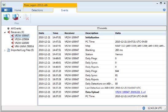
4.3.5        Exporting Detection Filters to Another Database ..................................................... 35

5 Managing Data ................................................................... 36
 5.1    Importing Data ................................................................................................................ 36
 5.2    Editing a VRL file ............................................................................................................ 38
   5.2.1     Correcting the Time Zone in a VRL .......................................................................... 39
   5.2.2     Correcting the Initialization Time in a VRL ............................................................... 40
   5.2.3     Correcting or Adding a Station Name to a VRL file .................................................. 40
 5.3    Managing Duplicate Tags in VUE ................................................................................... 41
   5.3.1     What is a duplicate tag?........................................................................................... 41
   5.3.2     Verifying a transmitter and its data ........................................................................... 43
 5.4    Removing files from VUE ................................................................................................ 44
 5.5    Viewing Millisecond Timestamps .................................................................................... 45
   5.5.1     Viewing millisecond timestamps in MS Excel ........................................................... 46
 5.6    Exporting Data ................................................................................................................ 46
 5.7    Metadata......................................................................................................................... 48
   5.7.1     What is Metadata? ................................................................................................... 48
   5.7.2     Transferring Metadata Between Databases ............................................................. 48

6 Viewing Events .................................................................. 50
    6.1.1    Events Tab .............................................................................................................. 50
    6.1.2    Events Ribbon ......................................................................................................... 50
    6.1.3    Events in the Selection Tree .................................................................................... 50
    6.1.4    Events Common to all Receiver Types .................................................................... 51
      6.1.4.1    Reset Event ...................................................................................................... 51
      6.1.4.2    Initialization Event ............................................................................................. 51
      6.1.4.3    Memory Capacity Event .................................................................................... 51
    6.1.5    Receiver-Specific Events ......................................................................................... 51
    6.1.6    “Old” Events............................................................................................................. 52
    6.1.7    Exporting Events...................................................................................................... 53

7 Additional Information ........................................................ 54
 7.1    VUE software .................................................................................................................. 54
   7.1.1    Installing VUE Software ........................................................................................... 54
   7.1.2    Auto Updates ........................................................................................................... 55
 7.2    Select VUE Options ........................................................................................................ 56
   7.2.1    Display Settings ....................................................................................................... 56
   7.2.2    Offload Settings ....................................................................................................... 56
   7.2.3    Export Settings ........................................................................................................ 57
   7.2.4    Devices .................................................................................................................... 57
   7.2.5    Managing Releases ................................................................................................. 58
   7.2.6    FDA Tool Settings.................................................................................................... 58
   7.2.7    Other VUE Settings ................................................................................................. 58
 7.3    Importing VR2 and VR3-UWM Text Data Files ............................................................... 59
   7.3.1    How does VUE display sensor data from VR2PC files? ........................................... 60

8 Frequently Asked Questions ................................................. 61
 8.1      How do I open a database? ............................................................................................ 61
8.2      Where do I find my VRL files?......................................................................................... 61
 8.3      How to I view my VRL files in VUE?................................................................................ 61
 8.4      What happens to multiple-copy detections? .................................................................... 61
 8.5      Can I adjust for clock drift on my receiver? ..................................................................... 61
 8.6      Can I import old VR2 data files? ..................................................................................... 61
 8.7      How do I view summary information about my VRL files? ............................................... 62
 8.8      How do I access statistics from my VRL files? ................................................................ 62
 8.9      How do I start over with my VRL Files? .......................................................................... 63
 8.10     How do I export my data for use in another application? ................................................. 63
 8.11     How do I separate date and time in my exported data? .................................................. 63
 8.12     How do I change option settings? ................................................................................... 63
 8.13     I deleted a receiver from VUE. What now? .................................................................... 63
 8.14     How do I export data into old VR2 format?...................................................................... 64
 8.15     Why does VUE want internet access? ............................................................................ 64
 8.16     Why do I get a window asking me to update my software (or firmware)? ........................ 64
 8.17     Why does VUE create two .VRL file types? .................................................................... 64
 8.18     What is “Hide this alert in future” for? .............................................................................. 65

9 Appendices....................................................................... 66
 9.1      Contact Information ........................................................................................................ 66
 9.2      Warranty and Disclaimer................................................................................................. 67
 9.3      Index............................................................................................................................... 68

       © (2015) AMIRIX Systems Inc. All rights reserved. The information contained herein includes
       information which is confidential and proprietary to AMIRIX Systems Inc. and may not be used
       or disclosed without prior written consent of AMIRIX Systems Inc.
       The Bluetooth® word mark and logos are owned by the Bluetooth SIG, Inc. and any use of such
       marks by AMIRIX Systems Inc. is under license. Other trademarks and trade names are those of
       their respective owners.

                                For the latest versions of user
                                 manuals and software, visit
                                           www.vemco.com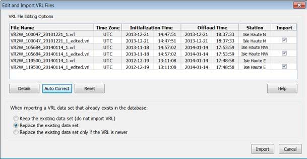
1 Introduction

   1.1       Overview of VUE Software
   The VUE (VEMCO User Environment) software has been developed to aid researchers in gathering,
   viewing, and analyzing acoustic detection data from VEMCO equipment. VUE employs a central database
   to allow the collection and viewing of data from multiple VEMCO receivers of various types.

   VUE uses receiver plug-ins to provide a receiver-specific communication link to perform such tasks as
   retrieving receiver data files, setting the receiver’s clock, clearing the receiver’s memory, and changing the
   receiver code map. Information on using VUE for this receiver-specific communication is located in the
   individual receiver user manuals.

   VUE can create one or more central databases combining data files from multiple
   receivers and multiple types of receivers (for example, VR4-UWM, VR2W, and                  VUE databases
                                                                                              combine detection
   VR2C). Old VR2 and VR3-UWM data files can also be imported into VUE                        data from multiple
   databases. Having a central database allows easy comparison between detections                 receivers!
   from multiple studies, across multiple years, and from various locations.

   You may choose to create smaller, temporary databases on laptops used for collecting data in the field. A
   larger, more central, database containing all receiver data files can then be created on a lab computer or
   network server.

   We advise that you always update to the latest version of VUE on your entire suite of PC's and laptops. By
   always using the latest version of VUE on all your PC’s and laptops, you can be assured of compatibility
   with all versions of compatable VEMCO monitoring receivers, both new and old.

   1.1.1      What can VUE do?

   VUE can…
       1. Setup receivers to record data (details found in related receiver manual)
       2. Collect data from receivers and create VRL files (details found in related receiver manual)
       3. Adjust data for clock-drift (see section 3.1)
       4. Filter data within the database (see section 4.3)
       5. Deal with duplicate tags (see section 5.3)
       6. Identify potential false detections for review (FDA tool, see section 3.2)
       7. View data in graphical form (see section 4.2)
       8. Export data (see section 5.6)
       9. Update receiver firmware (details found in related receiver manual)

VEMCO - VUE Manual                                                                                                  6
Export Files
                                                                         Selected data can be
                                                                      exported from the database
                                                                         into text file formats.

                                                                                                        Several
                                                                                     VEMCO              independent
     Receivers                                                                       Database           databases
                                                                                                        can easily be
                                                                                      (VDB)             created.

         Every offload from a
                                                                      VRL files can be imported into
         receiver generates a
                                                                        the database at any time.
             new VRL file.
                                           VEMCO
                                         Receiver Logs                          User Managed Backup
                                            (VRL)                                    of VRL files

   1.1.2      What’s a VRL file?
   A VRL file, or VEMCO Receiver Log file, is created each time data is offloaded from a receiver. VRL files
   are digitally encrypted/signed binary files that cannot be altered and provide a permanent record of the data
   stored by the receiver. A copy of these files should be stored in a
   safe location as a backup of the collected data. If you ever need to
                                                                                         Always store a backup
   restore your database, you can import the original data from your
                                                                                         copy of all your VRL
   VRL files.                                                                            files in a safe location!

   A VRL file contains all the information pertinent to the dataset,
   including the receiver configuration (code map, clock initialization, receiver serial number, deployment
   location, etc.) and, of course, the detection data. VRL files can be imported into any number of VUE
   databases, making it easy to share information.

   VRL files are named to allow you to identify the receiver to which they belong and the date that the data
   was offloaded. For example, the file VR2W_103047_20131130_1.VRL came from a VR2W receiver with
   the serial number 103047 and was offloaded on November 30, 2013. The “1” at the end indicates that it was
   the first offload of the day for that receiver using a particular PC.

VEMCO - VUE Manual                                                                                                   7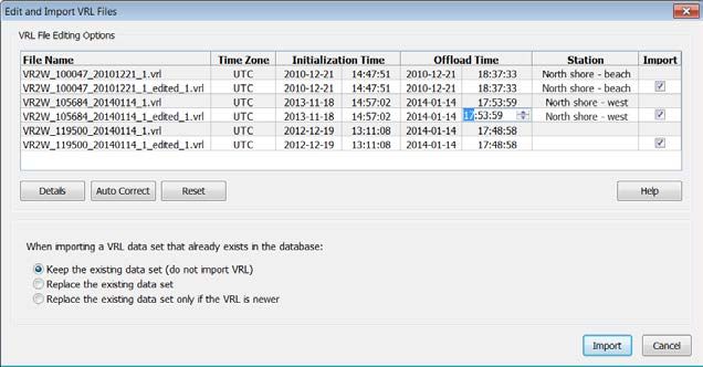
1.2        The order of things…
   A common question is “what tasks do I perform and in what order am I supposed to perform them?” The
   list below contains common tasks in a popular order.

       1.    Install VUE software (see section 7.1.1)
       2.    Setup VUE options (see section 7.2)
       3.    Create a database, if one doesn’t yet exist (see section 2.1)
       4.    Setup sensor tags and stations (see sections 2.2 and 2.3)
       5.    With the receiver(s) (details found in related receiver manual):
                 a. Initialize the study
                 b. Test receiver(s) in-air and in water
                 c. Deploy receivers and tags and wait…
                 d. Offload data from receivers
       6.    Time correct data (see section 3.1)
       7.    Import data into database, if not imported during Time Correction (see section 5.1)
       8.    Identify any potential false detections and remove as required (see section 3.2)
       9.    View data (see section 4)
       10.   Export data, if desired (see section 5.6)

   1.3        Software Tabs - an overview
   VUE has a number of tabs allowing access to detections, events, and receivers depending if a database is
   open and/or a receiver is connected.

   The File tab allows for databases to be created, opened, and closed, settings to be altered, and VRL files to
   be edited. The Home tab is used when connecting to a receiver and is explained in the receiver user manual.
   The Receiver tab is used, and only available, when VUE is communicating with a receiver, although
   multiple receivers can be in communication with VUE at once, requiring more than one receiver tab to be
   open (see receiver manual for more information).

   The tabs used during data analysis are the Detections tab (see sections 1.3.1 and 4) and the Events tab (see
   sections 1.3.2 and 6). This VUE manual focuses on the functions and information involved in these two
   tabs. The Home and Receiver tabs are discussed in the receiver user manuals.

     File          Home         Detections          Events          Receivers

VEMCO - VUE Manual                                                                                                 8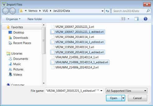
1.3.1       Detections Tab
   The Detections tab contains all the detections in the open database and is only visible if a database is open.
   From here, we can graph detections (section 4.2), search data for tag residency (section 3.3), import (section
   5.1) and export files (section 5.6), filter the data according to user-set parameters (section 4.3), add a new
   station (section 2.3.1) or transmitter record (section 2.2.1), and view data by receiver, transmitter, or station
   (section 4.1).

        The Detections Tab
                                                                       Must select the “Detections” tab
                                                                       to see detection information.
    The ribbon
    section contains
    functions that can
    be performed with
    the data, such as
    graphing or
    filtering data
    (section 4.1.1).

       Selection Tree:
       Select “All Detections”, a
       receiver, a transmitter, a
       station, a log file, or a filter to
       display the associated data
       in the right side of the VUE
       window.
       Each item in the list can be
       expanded as shown below
       so an individual receiver,
       transmitter, etc. can be
       viewed (section 4.1.2).

                                              The right side of the VUE window changes according to what’s
                                              selected in the tree on the left side of the window. If a receiver is
                                              selected, then this half of the window reports which tags were
                                              detected by that receiver. If a tag is selected, all of the detections
                                              in the database for that tag are shown. If a station is selected, all
                                              detections in the database recorded at that station are shown.

VEMCO - VUE Manual                                                                                                     9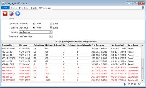
1.3.2        Events Tab
   The Events tab contains a list of key events that occurred to the receivers in the currently open database and
   is only visible if a database is open. From here, we can view events by receiver, import and export files, and
   delete individual log files. Event information is explained in more detail in section 6.

            The Events Tab
                                                                     Must select the “Events” tab
                                                                     to see events information.

   The ribbon section
   contains the tasks
   pertaining to the
   log files (section
   6.1.2).

   Selection Tree:
   Select “All Events” to view
   every event or select a
   receiver or a log file to display
   the associated event
   information in the right side of
   the VUE window.
   Each item in the list can be         The right side of the VUE window changes according to what’s selected
   expanded so an individual            in the tree on the left side of the window. If a receiver is selected, then
   receiver or file can be viewed       this half of the window reports the events that occurred to that receiver.
   (section 6.1.3).                     If a log file is selected, the events contained in that file are shown here.

   1.4        Getting Help
   While VUE is open, you can access the user manual for VUE and for the
   receivers that are used with VUE by selecting the “Help” icon near the top right
   corner of the window (blue circle with question mark). When this icon is
   selected, a list of the available manuals will appear and you can select the
   manual related to your question. For example, if you have a question about
   communicating with the VR2W, then select the VR2W manual.

           The manuals in VUE Help were current when the software was
        compiled. See www.vemco.com for the latest version of the manuals.

VEMCO - VUE Manual                                                                                                     10
2 Getting VUE Started
This section of the VUE manual, Getting VUE Started, has the necessary information to get you started
using VUE for your data analysis. After you’ve collected the data from your receivers as explained in the
user manual for your receiver(s), the remaining sections of this manual will explain how to prepare, view,
and export your data.
2.1 Open or Create a Database
To view data that has been offloaded from various VEMCO receivers, we must first create a new database
or open an existing database.
Begin by selecting the File menu button in the top left corner of the VUE software (circled
at right). From the menu that appears, choose “New Database” to create a new database or
choose “Open Database” to open an existing database (see below).
File menu button
Regardless of your choice, the window entitled “Open or Create a new database” opens to allow you to
select an existing database from the list shown or to enter the name of the new database in the “File name”
box.
If you are opening a database created by an earlier version of VUE (version 1.4.4 or older), you will receive
a warning that the database will be converted to the new version of VUE and will no longer be compatible
with older versions of the software.
TIP: After a database is opened, it will automatically open each time you
re-open VUE. This feature can be disabled, if desired, in the
Options window (see section 7.2.7).
VEMCO - VUE Manual 112.2 Set Up Tags Coded tags will
be detected
without being
Coded pingers (tags without sensors) do not need to be entered in VUE to be detected and setup.
identified. Tags with sensors (or Sensor Tags) can be detected without entering their
information in VUE but the data they report is in Analog to Digital Converter units, or ADC. To view the
data in the applicable units, the slope and intercept of the sensor (found in the Transmitter Specifications
received with your tags) must be entered in VUE. This can be done before the tag is deployed (section
2.2.1) or after the tag has been detected and imported into the database (section 2.2.2). The sensor tag setup
information can be sent from VEMCO in a VEMCO XML file format (*.vxm) and then imported into VUE
(see section 5.1). Check with VEMCO for more information.
Tag calibration information is not stored in the receiver but instead is kept within the VUE database.
Therefore, it is not necessary to enter tag calibration information into VUE before initializing and deploying
a receiver. Tag calibration information can be exchanged between databases using the Export Metadata and
Import Metadata features described in section 5.7.
2.2.1 Add Information for a New Sensor Tag
If a sensor tag has not been detected and entered in a VUE database, then the steps below will allow you to
enter the necessary information for the data to be displayed in the proper units (units selected in the Options
window, section 7.2.1).
STEP 1
Open the Add Transmitter window by either clicking on the “Add a new
transmitter record” icon in the Detections ribbon (shown below) or by
right-clicking on the transmitter list and
selecting “Add Transmitter” (shown at far right).
STEP 2
Enter the information in the Add Transmitter window. This information
is provided in the Transmitter Specifications manual that was shipped
with the tags. The Coding Type (at the top) and the Sensor Type (at
the bottom) are selected from drop-down lists.
Click “OK” when finished.
If you choose to name the tag, DO NOT use
the same name for more than one tag. This
causes confusion in the database.
TIP: To ease the task of adding sensor tag information to VUE, try importing the detection data
collected during your in-air testing (instructions found in receiver manuals; test every sensor
tag). Once the data is in VUE, follow the instructions in section 2.2.2 to edit the tag
information to include the serial number and calibration information.
VEMCO - VUE Manual 122.2.2 Edit Information for an Existing Sensor Tag
If a sensor tag has been detected and entered in a VUE database without first being setup, then the steps
below will allow you to enter the necessary information for the data to be displayed in the proper units (units
are selected in the Options window, section 7.2.1). As mentioned in the tip found in section 2.2.1, it is
sometime easier to enter a sensor’s information after the tag has been detected by a receiver. In-air testing
performed before the equipment is deployed, as described in the receiver manuals, not only ensures the
equipment is functioning properly but can also be used to aid in entering sensor tag information. Also, the
sensor tag setup information can be sent from VEMCO in a VEMCO XML file format (*.vxm) and then
imported into VUE (see section 5.1). Check with VEMCO for more information.
STEP 1
Highlight the sensor tag in the Transmitter section of the Selection Tree.
STEP 2
Open the Edit Transmitter window by either clicking on the “Edit
the selected transmitter record” icon in the Detections ribbon
(identified below) or by right-clicking on the tag’s ID number in the
transmitter list and selecting “Edit Transmitter” (shown at right).
STEP 3
Enter the information in the Edit Transmitter window. This
information is provided in the Transmitter Specifications manual
that was shipped with the tags. The Sensor Type (at the bottom)
is selected from a drop-down list.
Click “OK” when finished.
If you choose to name the tag, DO NOT use
the same name for more than one tag. This
causes confusion in the database.
VEMCO - VUE Manual 132.3 Set Up Stations
As receivers are portable units easily moved from one location to another, VUE has A station is used to
identify the location
provided the option to associate a receiver with a station (location) for a particular
of the receiver
deployment. This is setup when the user configures the receiver (see Start a Study
during deployment.
in the receiver manual). The station specifies a location, including latitude and
longitude (if desired), which is assigned and recorded in the receiver’s memory
during initialization.
Multiple receivers can be associated with the same station name and a receiver
can be associated with multiple stations.
Selecting a station name in the Detections tab (see section 4.1.2) will show all
detections in the open database from that station, including those from multiple
receivers.
It is possible to associate detections with a station after the data has been offloaded from a receiver, but the
original VRL file will not contain any location information. This post-deployment editing is explained in
section 2.3.2).
WARNING: DO NOT give multiple
locations the same Station Name.
This causes confusion in the database.
2.3.1 Add a New Station
To associate a receiver with a particular station before it is deployed, you must first use VUE to add a station
name to your database. Follow the steps listed below to add a station.
STEP 1
Open the Add Station window by either clicking on the “Add a new station
record” icon in the Detections ribbon (shown below) or by right-clicking on
the station list and selecting “Add Station”
(shown at far right).
Continued…
VEMCO - VUE Manual 14STEP 2
Enter the location’s unique name in the box labelled “Name”. The station name will be used to identify the
station in the selection tree and in the Station field of the database. This name should be unique from all
other station names.
Optionally, enter the location’s latitude and longitude in the
boxes marked “latitude” and “longitude”. There are various
formats that will be recognized and you may use any of the
formats listed in the table below when inputting your data.
Hemisphere must be indicated by either using +/- or by N/S/E/W.
Regardless of which format of “latitude” and “longitude” you
choose to input, the default display setting is in +/- Degrees and
will automatically convert to that format. This default display can
be changed in the Options window (see section 7.2.1).
Format Latitude Longitude
+44.64085 -063.67083
Degrees 44.64085° N 063.67083° W
N44.64085 W063.67083 Always use unique station
names (no two stations with
44°38.451′ N 063°40.250′ W
the same name) to avoid
Degrees/Mins N4438.451 W06340.250 confusion in the database.
+4438.451 -06340.250
44°38′27.07″ N 063°40′14.98″ W Enter a description of the location in the
Degrees/Mins/Secs N443827.07 W0634014.98 “Description” box for your reference.
+443827.07 -0634014.98 Click “OK” when finished.
TIP: Holt the “Alt” key and type “248” on the number
pad to enter the degree symbol (°).
2.3.2 Edit a Station
It is possible to change the station association of a detection or group of detections. To do so, select the
desired detections and “drag and drop” them onto the correct station name within the station selection tree.
Remember that you can use Shift key to select a group of detections together. If you want to change the
station for an entire VRL file, see section 5.2.3.
You can also edit a station name, the
location, and/or the description
associated with a station. When
station information is changed, it
will change for all data associated
with the original station name. It’s
better to edit a station name rather
than delete a station and then add a
new station at the same location
because the data association is lost
when a station is deleted.
Edit a station rather than
delete it and add a
replacement.
VEMCO - VUE Manual 15Follow the steps below to edit an existing station’s information.
STEP 1 STEP 2
Highlight the station in the Stations Open the Edit Station window by either clicking on the “Add a new
section of the Selection Tree. station record” icon in the Detections ribbon (on left, below) or by
right-clicking on the station in the list and selecting “Edit Station” (on
right, below).
STEP 3
Enter the location’s unique name in the box labelled “Name”. The station name will be used to identify the
station in the selection tree and in the Station field of the database. This name should be unique from all
other station names.
Optionally, enter the location’s latitude and longitude in the
boxes marked “latitude” and “longitude”. There are various
formats that will be recognized and you may use any of the
formats listed in the table below when inputting your data.
Hemisphere must be indicated by either using +/- or by N/S/E/W.
Regardless of which format of “latitude” and “longitude” you
choose to input, the default display setting is in +/- Degrees and
will automatically convert to that format. This default display can
be changed in the Options window (see section 7.2.1).
Format Latitude Longitude
+44.64085 -063.67083
Degrees 44.64085° N 063.67083° W
N44.64085 W063.67083 Always use unique station
44°38.451′ N 063°40.250′ W
names (no two stations with
the same name) to avoid
Degrees/Mins N4438.451 W06340.250 confusion in the database.
+4438.451 -06340.250
44°38′27.07″ N 063°40′14.98″ W Enter a description of the location in the
Degrees/Mins/Secs N443827.07 W0634014.98 “Description” box for your reference (optional).
+443827.07 -0634014.98 Click “OK” when finished.
TIP: The degree symbol (°) can be entered on the keyboard by holding the “Alt” key
while typing “248” on the number pad.
VEMCO - VUE Manual 163 Data Analysis – the basics
Data processing with VUE begins by collecting the data from the various receivers being used in a study.
The data collection, or Offloading, process is explained in detail in the various receiver user manuals. Some
additional steps are: time correcting data files (section 3.1), removing false detections (section 3.2), and
performing residency searches if desired (section 3.3).
3.1 Time Correction
What is time correction and why should you do it? VEMCO submerged receivers rely on crystal oscillators
to keep track of time. Due to manufacturing variations, the frequency of the crystal oscillators varies
slightly between receivers. Each receiver’s internal clock will drift – losing or gaining up to 4 seconds per
day. This time drift can be caused by changes in temperature and/or
variations in the oscillator. For this reason the drift is highly linear and can We strongly recommend
be corrected. you time-correct the data
before beginning any
As for why, time correcting aids in lining up your detections to make sure the analysis of the data.
detections from all the receivers in your study are giving you data for the
same time period. For example, if five receivers receive the same transmission from Fish A, the time stamp
of the detection can very between the receivers by as much as 15 minutes. This variance may lead a person
to believe that multiple detections of this animal were made on multiple receivers in the area, but it’s
actually caused by the clock-drift of the receivers. Correcting this clock-drift would reveal it is a single
detection on multiple receivers.
STEP 1 STEP 2
Establish that the PC clock was correct when the receiver Open the File menu (circled below) and
was initialized and when the data was offloaded. Time select Tools → VRL File Editor (see arrow
correction is performed based on the assumption that the below).
initialization and offload times are both correct. If either is
incorrect then the time
correction changes will
be incorrect. Times can
be edited if necessary
(see Step 4).
Continued…
VEMCO - VUE Manual 17STEP 3
Select the VRL files you wish to time correct.
You may edit multiple files at one time by holding the CTRL key while
selecting multiple files with the mouse.
Click “Open”.
Your default location will open automatically.
See section 7.2.2 to change your default location.
STEP 4
Select the Auto Correct button in the VRL
editing window.
Notice that beneath each chosen file
is a new file with “_edited” appended
If needed, reset any
to the filename. Your existing VRL
files will not be altered but a new changes made manually
edited file will be created and stored or with the Auto Correct
with your existing VRL files. button to the dates, times,
or time zones.
If a date, time, or time zone is incorrect, click on the incorrect information
in the white line (edited file) and make the necessary change(s). Make sure the Auto Correct button is
selected after the change has been made.
STEP 5
Select from the three options listed at the bottom of the window to tell VUE what to do if the VRL has already
been imported.
Watch for very large differences in times
between the offloaded time and the corrected
offloaded time as this may indicate there’s a
problem.
If you’re uncertain if the times in a VRL file are
correct, then uncheck the “Import” box on the
right to not import that VRL file into the
database, look into the issue, and import the file
later. Corrected times are
shown in red.
Click “Import” to save the edited files and import
the corrected data into the open database.
TIP: Hover your mouse pointer over the boundary between two column titles to adjust column widths.
VEMCO - VUE Manual 183.2 Remove False Detections (FDA Tool)
All communication systems experience transmission errors which can result in false detections – i.e.
detections of animal tags that are not present. The Vemco system is quite conservative in its approach and
thus the number of false detects is normally low, however they can still occur. The FDA (False Detection
Analysis) tool is designed to allow you to quickly identify the detections that may be questionable and
therefore require further scrutiny. This tool does not state that the identified detections are false, but rather
that the detections occurred in such a way that further analysis is needed before determining if the detection
was false or not.
The FDA tool is based on an algorithm that uses the premise that false detections are generally separated by
long intervals with only occasional short intervals. Details on the algorithm can be found in the application
note False Detections: What They Are and How to Remove Them from Detection Data available from our
website at http://vemco.com/wp-content/uploads/2012/11/false_detections.pdf.
The FDA tool analyzes your detection data and determines, on a receiver to tag basis, the number of short
and long intervals between detections. Those tag-receiver records for which there are more long intervals
than short intervals are flagged as questionable data and require additional scrutiny before being accepted by
the researcher as valid data.
3.2.1 Using the FDA (False Detection Analysis) tool
STEP 1 STEP 2
Open VUE and open the Select the
database (if not already Detections tab to
open – see section 2.1 bring the
about automatically Detections ribbon
opening a database). into view.
STEP 3 STEP 4
Select the database Select “FDA Analyzer” to
search icon open the FDA Analyzer
(magnifying glass) tab.
Continued…
VEMCO - VUE Manual 19STEP 5
Select a start and end date and time, if desired. The location
(receiver) and transmitter can also be selected, or you can
leave them as “Any Receiver” and “Any Transmitter” and all
the data in the database will be analyzed
STEP 6
Click the blue “Execute” button and wait
for the results. Any tags that have more
long intervals than short intervals in the
database are shown in red, and the
acceptance is listed as “Questionable”.
3.2.2 Reviewing “Questionable” Data
It’s important to note that FDA analysis does not conclusively determine that the “questionable detections”
are false, only that the data requires further scrutiny. Some things to consider when looking at questionable
data are:
1. Detection activity. If there are many tags around a receiver, tag collisions can happen and can cause
false detections. Single detections, or multiple detections spaced far apart recorded in the presence of
other tags should be viewed very cautiously as they are most likely false.
2. Detections of a certain ID number on other receivers may provide you with enough confidence to
classify a questionable detection as real, assuming the timing makes sense.
3. Fixed tags or range test tags – if you have deployed tags for a range test and they are on the edge of
the detection range, it will be normal for them to fade in and out during the range testing. Depending
on the range performance these could look like detections that are separated by long intervals and thus
flagged as questionable even though they are legitimate detections.
VEMCO - VUE Manual 204. The short and long intervals are set up by default as 30 minutes and 12 hours respectively. This works
well with normal tag delays (e.g. 30 sec to 5 minute delays). If your tags have very long random
delays – tens of minutes and longer – you may not detect any short intervals and thus they are flagged
as questionable even though they are valid detections. The default interval times can be changed as
required (see below).
5. High Residency situation – if you have a large number of tags resident around a receiver, you may
expect to see longer intervals between tag detections due to tag collisions. It may be necessary to
stretch out the minimal interval for the FDA analysis to allow for these longer intervals.
6. Finally, when in doubt call us. We are happy to have our team of experts review your data and
provide guidance on whether to accept detections as real.
3.2.3 Changing FDA Interval times
There are situations when the FDA tool’s default interval times may need to be adjusted according to the
needs of your data. If you decide to do so, access to the FDA Parameters by opening the Options window
(see section 7.2.6) and selecting the FDA Tool tab. The default times are shown in the window below.
VEMCO - VUE Manual 213.3 Residency Search
The residency search option provides a method of reducing the data by accumulating the number of
detections during a fixed period of time. You can specify the start and stop times and the number of
detections to be considered residency (i.e. how many times must a tag be detected before it’s considered in
residence). The “Absence Threshold” allows you to specify the maximum time between detections to be
considered part of a single residency period. Specific receivers or transmitters can be selected as parameters
of the residency search.
Residency Search is particularly helpful if you are working in a fixed area, such as a reef, and you wish to
know when the tagged animals left the area and when they returned but you are not too interested in what
they were doing while they were in the area.
Follow the steps below to use Residency Search:
STEP 1 STEP 2
Open VUE and open the Select the
database (if not already Detections tab to
open – see section 2.1 bring the
about automatically Detections ribbon
opening a database). into view.
STEP 3 STEP 4
Select the database Select “Residency
search icon Search” to open the
(magnifying glass). Residency tab.
STEP 5
Enter the desired start and end times within which to search.
Also, if desired, select a location (receiver or station) to search
for a specific tag to search for. Both are drop-down lists. The
defaults are “Any receiver” and “Any transmitter”.
The “Sort By” field lets you select if the results will be listed
based on when a tag arrived or when it departed.
Continued…
VEMCO - VUE Manual 22STEP 6
Select the Absence Threshold, the maximum length of time
permitted between detections within a single residency period, and the
Detection Threshold, the minimum number of detections required for
a residency to be reported.
The Allow residencies to span time limits option, when enabled,
allows residencies to span the start and end time limits. When
disabled, residencies are cut off before the limit.
STEP 7 STEP 8
Click the “Execute the search”
button to begin the search.
Export the search results
The results are listed in the as a CSV file by clicking
lower section of the window. the “Export search results
as a CSV file” icon and
entering a directory and
file name.
STEP 9
Close the Residency tab by clicking the red “X” icon in the ribbon.
More than one Residency tab can be open at the same time.
VEMCO - VUE Manual 234 Viewing Data
Data is retrieved from receivers using the Offload feature. Specifics for offloading data are described in the
receiver’s user manual. If a database is open when the data is offloaded from a receiver, then a prompt will
ask if the data should be imported into the open database. Data can be added to a database at any time by
importing the .VRL file(s) into VUE.
4.1 Viewing Detections
The Detections tab contains all the detections in the open database and is only
visible if a database is open (see section 2.1 for opening a database). While
in the Detections tab, it’s possible to graph detections, search data for tag
residency, import and export files, filter data according to user-set
parameters, add/edit station or transmitter information, and view data by
receiver, transmitter, or station.
Name of open database Must select “Detections” tab
The ribbon to see detection info.
section contains
functions that can
be performed with
the data, such as
graphing or
filtering data (see
section 4.1.1)
Selection Tree:
Select “All Detections”, a receiver, a
transmitter, a station, a log file, or a
filter to display the associated data in
the right side of the VUE window.
Each item in the list can be expanded
so an individual receiver, transmitter,
etc. can be viewed (see section 4.1.2).
The right side of the VUE window changes according to what’s selected in the tree on the left side of the
window. If a receiver is selected, then this half of the window reports which tags were detected by that receiver.
If a tag is selected, all of the detections in the database for that tag are shown. If a station is selected, all
detections in the database recorded at that station are shown.
VEMCO - VUE Manual 244.1.1 Detections Ribbon
Selecting the Detections tab will bring the Detections Ribbon to the fore, allowing any of the available
features to be selected. Each feature is explained elsewhere in the manual – see the references below.
Chart data Filter data Station (receiver location)
(section 4.2). (section 4.3). information (section 2.3).
FDA tool (section 3.2) or Residency Import (section 5.1), export (section Transmitter (tag) information,
Search (section 3.3). 5.6), or delete (section 5.4) files. particularly sensor tags (section 2.2).
4.1.2 Detections in the Selection Tree
The selection tree on the left side of the window allows access to the detections of individual receivers,
transmitter, stations, imported log files, and detection filters. Clicking on the symbol next to a category
will open the expanded view, as shown below.
4.1.3 Viewing All Detections
To view all detections in a database, first select the Detections tab at the top of
the window. This tab is only visible when a database is open. Select “All
Detections” at the top of the selection tree on the left hand side of the VUE
window. All detections, sorted by date, will be listed on the right-hand side of
the screen.
VEMCO - VUE Manual 254.1.4 Viewing Detections by Receiver
Receivers are uniquely named according to their model and serial number, for
example, VR2W-100282. To view detections collected with a specific receiver,
select the receiver in the selection tree on the Detections tab. All detections from
that receiver, sorted by date, will be listed on the right-hand side of the screen.
4.1.5 Viewing Transmitter Detections
Each transmitter is provided an ID number at the factory. The transmitter data sheet which was shipped with
the transmitter will provide the ID number, the transmitter serial number, and the transmitter code space (see
section 4.1.5.2). Within VUE, the default transmitter name will be displayed as a combination of the code
space and the ID number. By selecting the transmitter name in the list on the left side of the VUE detections
window, VUE will show all detections found in the current database for that transmitter.
Default Transmitter Name: code_space – ID#
example: A69-1601-6185
4.1.5.1 Transmitter name
A transmitter can also be assigned a user-defined name. To do this, highlight the tag in the selection
tree and click the Edit selected transmitter in the Transmitter section of the Detections ribbon (shown
at right), or right-click on the tag in the selection tree and select Edit transmitter. Either method will
open the Edit Transmitter window shown below. The serial number and a user-defined name can be
entered to be assigned to that tag.
The user-defined transmitter name will appear in the “Transmitter”
column on the right hand side of the VUE window when “All
Detections”, “All Events” or a receiver, station, log file, or filter is
selected on the left hand side. The database columns “Code Space”
and “ID” will still contain the code space and transmitter ID.
Default
transmitter name
User-defined
name
VEMCO - VUE Manual 264.1.5.2 Nomenclature for Code Maps and Code Spaces
A Code Space is a term used to describe the type of coding scheme used for a particular tag type. VEMCO
has various coding schemes available to support a large number of unique IDs. In the past, these have been
described with a series of parameters such as R4K, sync 340 ms, bin 20 ms,
etc. This required our customers to know the intricate details of the coding Code Space describes
scheme, which could lead to confusion and error. VUE now uses unambiguous everything the receiver
nomenclature that provides each coding scheme with a unique identifier that needs to know about that
encompasses all of the information required for the receiver to detect that tag. transmitter
Tag datasheets include this identifier.
An example of a valid Code Space label is A69-1601. The “A69” indicates an Acoustic Tag operating at a
frequency of 69 kHz. The “1601” is a unique number that is understood by the receiver firmware to
determine how to detect and decode the tags. VUE will report tag detections as Code space-ID# by default.
Datasheets sent to the customer with each tag order will contain this label. It is important to note that a tag
that transmits a Code space-ID#, e.g., A69-1601-2056, is a different transmitter then one with a label of
A69-9001-2056. The ID codes are the same but the coding scheme is different!
A Code Map describes a collection of Code Spaces. When a receiver is configured with a particular Code
Map, it can detect and decode all types of transmitters in that map.
4.1.6 Viewing by Station
As receivers are mobile units easily moved from one location to another, VUE
has provided the option to associate a receiver with a station (location) for a A station is used to
identify the location of
particular deployment. The station specifies a location, including latitude and
the receiver during
longitude (if desired), which is assigned and recorded in the receiver’s memory deployment.
during initialization. More information on stations is found in section 2.3.
VEMCO - VUE Manual 274.2 Plotting Data
Any data displayed in the Detection tab can be plotted by time. The plot can be viewed by selecting
the “Chart Detections” icon in the Detections ribbon (shown at right). The detections plotted are
selected using the selection tree on the left. Selecting a transmitter will plot all the detections from
that transmitter, grouped by receiver. Selecting a receiver will plot all the detections from that receiver,
grouped by transmitter. Selecting “All Detections” will plot all database detections, grouped by transmitter.
Adding or removing data from the database automatically updates the plot.
There are two plot display modes in VUE: a detail mode that includes details with each datum and an
overview mode. When you first generate a plot, the data is shown in Detail mode. In this mode, the plot
window is capable of simultaneously displaying up to 8192 detections. The number of detections currently
displayed, as well as the total number of detections in the selected data are shown on the top left of the plot
window. The black section of the grey bar at the top of the plot indicates which portion of your selected
data you are currently viewing. In the example below, the plot shows the first 2048 of all 81,728 detections
for the receiver VR2W-100248.
Group detections based on
Multiple Chart tabs one of these groups (from
can be open at the down-down list): Transmitters;
same time Receivers; Stations.
Close
Chart
tab
Navigation tools as
described in the table
on following pages
Detections can be grouped by transmitters, receivers, or stations. The legend on the right hand side of the
window provides a list of the transmitters, receivers, or stations for which detections are currently visible on
the plot.
To view all detections in your database simultaneously, click on the “Overview” button in the navigation
tools (below the chart). Overview mode will display all detections but will not display the details of each
detection.
VEMCO - VUE Manual 28To return to detail mode, click on the
“Detail” button at the bottom of the
plot window (this replaced the
“Overview” button).
For large datasets, overview mode may take considerable time to display. For this reason, VUE provides the
option to abort loading the overview plot. To do so, click on the “Abort” button at the bottom left of the plot
window.
To more easily distinguish the time of day each transmission was detected,
you can opt to select the Day/Night Shading box above the chart. When
selected, a dialog box initially appears where you can set the sunrise and
sunset times or use latitude and longitude values. The plot will then show
any night detections with a shaded area, as shown in the sample below.
VEMCO - VUE Manual 29The Chart tab contains several navigation tools to help browse your data. These are listed and described in
the table below.
Button Description
Go to the beginning of the data selection
Go to the end of the data selection
Skip back one display page (keyboard left arrow)
(or keyboard left arrow)
Skip forward one display page (keyboard right arrow)
(or keyboard right arrow)
Display a shorter time range. You can also zoom in on a particular area
by clicking anywhere on the graph and dragging to define a time range.
(or keyboard down arrow)
Display a longer time range (keyboard up arrow)
(or keyboard up arrow)
Display entire dataset at once
In both detail and overview modes, moving the mouse pointer over any point on the
plot will display the transmitter ID number, the receiver it was stored on, and the date
and time details of that detection (see example at right).
VEMCO - VUE Manual 30You can also read