AVOCENT AUTOVIEW 2108/2216/3108/3216 SWITCH - INSTALLER/USER GUIDE - VERTIV
←
→
Page content transcription
If your browser does not render page correctly, please read the page content below
Avocent® AutoView™ 2108/2216/3108/3216
Switch

Installer/User Guide
The information contained in this document is subject to change
without notice and may not be suitable for all applications. While
every precaution has been taken to ensure the accuracy and
completeness of this document, Vertiv assumes no responsibility
and disclaims all liability for damages resulting from use of this
information or for any errors or omissions. Refer to other local
practices or building codes as applicable for the correct methods,
tools, and materials to be used in performing procedures not
specifically described in this document.

The products covered by this instruction manual are manufactured
and/or sold by Vertiv This document is the property of Vertiv and
contains confidential and proprietary information owned by Vertiv.
Any copying, use or disclosure of it without the written permission
of Vertiv is strictly prohibited.

Names of companies and products are trademarks or registered
trademarks of the respective companies. Any questions regarding

 Technical Support Site

 If you encounter any installation or operational issues with your product, check the pertinent
 section of this manual to see if the issue can be resolved by following outlined procedures.
 Visit https://www.VertivCo.com/en-us/support/ for additional assistance.

                                                              Vertiv™ | Avocent® AutoView™ 2108/2216/3108/3216 Switch Installer/User Guide
TABLE OF CONTENTS
1 Product Overview 1
1.1 Features and Benefits 1
1.1.1 Reduce cable bulk 1
1.1.2 IQ modules 1
1.1.3 Multiplatform support 1
1.1.4 User interfaces 1
1.1.5 Security 2
1.1.6 Virtual media and smart card support 2
1.1.7 IPv4 and IPv6 capabilities 2
1.1.8 Access the AutoView™ switch using a standard TCP/IP network 3
1.1.9 Upgradeable 3
1.1.10 Two-tier expansion 3
1.1.11 KVM remote access 3
1.1.12 Avocent® DSView™ management software plug-in 3
1.1.13 Local video scaling 3
1.1.14 Encryption 3
2 Installation 5
2.1 Setting Up Your Network 5
2.1.1 Keyboards 5
2.2 Quick Setup 5
2.3 Connecting the AutoView™ Switch Hardware 5
2.4 Tiering Your Switch Using an IQ Module 8
2.4.1 Adding a tiered switch 9
2.4.2 Adding a tiered legacy switch 11
2.5 Configuring Your Switch 13
2.6 Setting Up the Built-in Web Server 13
2.7 Connecting to the OBWI Through a Firewall 13
2.8 Verifying Power Status 14
2.9 Adjusting Mouse Settings on Target Devices 14
3 Local OSCAR™ User Interface 17
3.1 Main Dialog Box Functions 17
3.1.1 Viewing and selecting ports and devices 17
3.1.2 Viewing switch system status 18
i3.1.3 Selecting devices 19
3.1.4 Soft switching 20
3.1.5 Navigating the OSCAR interface 20
3.1.6 Connecting local virtual media 21
3.2 Setup Dialog Box Functions 22
3.2.1 Changing the display behavior 23
3.2.2 Controlling the status flag 24
3.2.3 Setting the keyboard country code 25
3.2.4 Assigning device types 25
3.2.5 Assigning device names 25
3.2.6 Configuring network settings 26
3.3 Commands Dialog Box Functions 26
3.3.1 Selecting devices for scan mode 27
3.3.2 Enabling or disabling scan mode 28
3.3.3 Viewing and disconnecting user connections 28
3.3.4 Displaying version information and upgrading firmware 28
4 OBWI Operation 31
4.1 Using the OBWI 32
4.2 Viewing System Information 32
4.3 Generating a Certificate 34
4.4 Tools - Rebooting and Upgrading 35
4.4.1 Rebooting the switch 35
4.4.2 Upgrading switch firmware 35
4.4.3 Saving and restoring configurations and user databases 36
4.5 Property Identity and Location Settings 37
4.6 Viewing Version Information 37
4.7 Network Settings 37
4.8 SNMP Settings 38
4.9 Auditing Event Settings 39
4.10 Setting Event Destinations 39
4.11 Ports Settings - Configuring an IQ Adaptor 39
4.11.1 Deleting IQ adaptors 40
4.11.2 Upgrading IQ adaptors 40
4.12 Launching a Session 40
4.12.1 General sessions settings 41
Vertiv™ | Avocent® AutoView™ 2108/2216/3108/3216 Switch Installer/User Guide
ii4.12.2 Local user account settings 41
4.12.3 Virtual media session settings 42
4.13 DSView™ Software Settings 43
5 LDAP 45
5.1 Configuring LDAP in the User Interface 45
5.1.1 LDAP Overview parameters 45
5.1.2 LDAP Search parameters 46
5.1.3 LDAP Query parameters 47
5.2 Appliance and Target Device Query Modes 48
5.3 Setting up Active Directory for Performing Queries 50
5.4 Active Sessions 51
5.5 Closing a Session 51
6 KVM Video Viewer 53
7 Terminal Operation 55
7.1 Network Configuration 55
7.2 Other Console Main Menu Options 56
7.2.1 Firmware management 56
7.2.2 Enable debug messages 56
7.2.3 Set/Change password 56
7.2.4 Restore factory defaults 56
7.2.5 Reset appliance 56
7.2.6 Set web interface ports 56
7.2.7 Exit 56
Appendices 57
Appendix A: MIB SNMP Traps 57
Appendix B: Setup Port Pinouts 61
Appendix C: Using Serial IQ Modules 62
Appendix D: Sun Advanced Key Emulation 67
Appendix E: UTP Cabling 68
Appendix F: Technical Specifications 70
iiiThis page intentionally left blank
Vertiv™ | Avocent® AutoView™ 2108/2216/3108/3216 Switch Installer/User Guide
iv1 PRODUCT OVERVIEW
The Avocent® AutoView™ 2108/2216/3108/3216 switch is an analog keyboard, video and mouse (KVM)
switch that provides flexible, centralized local access to data center servers. The 2108/2216 switch models
also provide centralized remote access to data center servers when used in conjunction with the optional
Remote Access Key (RAK-key).
1.1 Features and Benefits
1.1.1 Reduce cable bulk
With device densities continually increasing, cable bulk remains a major concern for network
administrators. The switch significantly reduces KVM cable volume in the rack by utilizing the innovative
IQ module and single, industry-standard Unshielded Twisted Pair (UTP) cabling. This allows a higher
device density while providing greater airflow and cooling capacity.
1.1.2 IQ modules
The switch supports IQ modules that are powered directly from the target device and provide Keep Alive
functionality when the switch is not powered. The IQ modules with CAT5 design dramatically reduce
cable clutter while providing optimal resolution and video settings. The built-in memory of IQ modules
simplifies configuration by assigning and retaining unique device names and Electronic ID (EID) numbers
for each attached device.
PS/2 and USB IQ modules are available allowing direct KVM connectivity to devices. A VMC IQ module is
also available. The switch is offered with 8 or 16 ARI ports that are used to connect IQ modules to the
switch. Then utilizing the IQ modules, you can attach additional switches to expand your switch system.
This flexibility allows you to add capacity as your data center grows.
NOTE: A patch panel is not recommended as a connection point between the appliance and an IQ
module because it can cause distance, power or video quality control feature issues. If the issues are
still present when the patch panel is removed, contact Technical Support.
1.1.3 Multiplatform support
Avocent® IQ module intelligent cabling can be used to connect local devices to the switch. PS/2 and USB
options are available. For more information, please refer to the appropriate installer/user guide for your
product or visit https://www.VertivCo.com for more information.
1.1.4 User interfaces
The switch is equipped with two “point-and-click” interfaces to manage the switch locally. They are the
local user interface (UI), referred to as the Avocent® OSCAR™ graphical user interface (GUI) and the on-
board web interface (OBWI). Using the configuration options provided by these interfaces, you can tailor
your switch to your specific application. The OBWI can also be used to access and control any attached
devices and handle all basic KVM needs remotely.
1NOTE: For the 2108/2216 switch models, remote KVM sessions via the OBWI require the installation of
the RAK-key.
OSCAR™ graphical user interface
The OSCAR user interface, accessed using the local port, features intuitive menus and operation modes
to configure your switch and devices. Devices can be identified by name, EID or port number.
1.1.5 Security
The recommended usage for the switch is in a data center infrastructure protected by a firewall. The
interface allows you to protect your system with a window saver password. When the window saver mode
engages, access is prohibited until the appropriate password is entered to reactivate the system. By
typing Help in the password dialog, you are directed to Technical Support.
OBWI
You can also use the OBWI to manage your switch. The OBWI is launched directly from the switch and
does not require a software server or any installation. With the addition of the optional RAK-key installed,
you can also establish remote KVM and virtual media sessions to target devices. For more information, see
Product Overview on page 1.
NOTE: RAK-key installation is only applicable for the 2108/2216 switch models.
Terminal console interface
The terminal console interface is accessed through the "SETUP" port. A terminal window or a PC running
terminal emulation software can be used to access the interface.
1.1.6 Virtual media and smart card support
The switch allows you to view, move or copy data located on local media and smart cards. Smart cards are
pocket-sized cards that store and process information, including identification and authentication
information, to enable access to computers, networks and secure rooms or buildings.
A virtual media or a smart card reader can be connected directly to the USB ports on the switch. In
addition, virtual media or smart card readers can be connected to any remote workstation that is running
the remote OBWI, switch software or DSView management software and is connected to the switch using
an Ethernet connection.
NOTE: To open a virtual media or smart card session with a target device, you must first connect the
target device to a switch using a USB2 or VMC IQ module.
1.1.7 IPv4 and IPv6 capabilities
The switch is compatible with systems using either of the currently used Internet Protocol Versions, IPv4
or IPv6. You can change the network settings and choose either IPv4 or IPv6 mode via the terminal
console, OSCAR interface or OBWI.
Vertiv™ | Avocent® AutoView™ 2108/2216/3108/3216 Switch Installer/User Guide
21.1.8 Access the AutoView™ switch using a standard TCP/IP network
The device is accessible for configuration via the standard TCP/IP network. If the optional RAK-key is
installed, you can access all attached systems via Ethernet. See Product Overview on page 1.
NOTE: The client connects to the switch using an Internet browser.
NOTE: KVM over IP sessions are supported on the 2108/2216 switch models when the RAK-key is
installed. RAK-key installation is only applicable for the 2108/2216 switch models.
1.1.9 Upgradeable
Upgrade your switch at any time to ensure you are always running the most current firmware version
available. For more information, see Tools - Rebooting and Upgrading on page 35.
1.1.10 Two-tier expansion
The switch allows you to tier one additional switch from each ARI port on the primary switch. Each tiered
switch is attached in the same manner as any device. This additional tier of units allows you to attach up
to 256 servers in one system. See Tiering Your Switch Using an IQ Module on page 8.
1.1.11 KVM remote access
A single KVM remote user is supported. You can manage remote operating system installation, operating
system recovery, hard drive recovery or duplication, BIOS updating and server backup. You must install
the optional RAK-key to a USB port to enable KVM remote access on the 2108/2216 switch models.
1.1.12 Avocent® DSView™ management software plug-in
The DSView management software can be used with the switch to allow IT administrators to securely and
remotely access and monitor target devices on multiple platforms through a single, web-based user
interface. A session can be launched to a device from a single point of access. For more information, see
the Technical Bulletin for the DSView management software plug-in.
1.1.13 Local video scaling
The switch digitizes a video signal with a maximum pixel resolution of up to 1600 x 1200 or 1680 x 1050
(widewindow), depending on the length of cable separating your switch and devices.
1.1.14 Encryption
The switch supports AES encryption of keyboard/mouse, video and virtual media sessions.
1 Product Overview 3This page intentionally left blank
Vertiv™ | Avocent® AutoView™ 2108/2216/3108/3216 Switch Installer/User Guide
42 INSTALLATION
The switch uses TCP/IP for communication over Ethernet. For the best system performance, use a
dedicated, switched 10Base-T or 100Base-T Ethernet network.
You can use the terminal software, OSCAR interface or the OBWI to manage your switch system. The
OBWI manages a single switch and its connections. You can also perform KVM and serial switching tasks
using the OBWI or DSView management software. The optional RAK-key is required to use the remote
KVM feature on the 2108/2216 switch models. For more information about DSView management software,
visit http://www.VertivCo.com.
NOTE: Ensure that every switch has been upgraded to the most recent version of firmware. For
information on upgrading the switch using the OBWI, see Tools - Rebooting and Upgrading on page
35.
2.1 Setting Up Your Network
The switch uses IP addresses to uniquely identify the switch and attached devices. The switch supports
both Dynamic Host Configuration Protocol (DHCP) and static IP addressing. Make sure that an IP address
is reserved for each switch and that each IP address remains static while the switch is connected to the
network.
2.1.1 Keyboards
A USB keyboard and mouse can be connected to the analog ports of the switch.
NOTE: The switch also supports the use of multiple keyboards and multiple mice on the analog port.
The use of more than one input device simultaneously, however, can produce unpredictable results.
2.2 Quick Setup
The following is a quick setup list. For detailed rack mounting and installation instructions, see the KVM
Switch Rack Mount Quick Installation Guide.
1. Unpack the switch and verify that all components are present and in good condition.
2. Install the switch hardware and connect an IQ module to each target device or tiered switch.
Connect each IQ module to the switch with CAT5 cabling and connect the keyboard, monitor
and mouse connectors to the analog ports of the switch.
3. Connect the local port peripherals to the appropriate ports on the back panel of the switch and
set up the network configuration. The IP address can be set here. Using a static IP address is
recommended.
4. For the local port connection, input all device names using the OSCAR interface or the OBWI.
5. Adjust mouse acceleration on each device to Slow or None.
2.3 Connecting the AutoView™ Switch Hardware
The following figure illustrates an example configuration for the AutoView switch.
5Figure 2.1 Basic Configuration
Vertiv™ | Avocent® AutoView™ 2108/2216/3108/3216 Switch Installer/User Guide
6Table 2.1 Basic Configuration Descriptions
ITEM DESCRIPTION ITEM DESCRIPTION
1 AutoView switch (16-port model shown) 7 ACI connection
External virtual media - USB
2 Power cord 8
connections
3 Analog users (2) 9 Target device ports
Digital user (requires the RAK-key; only applicable for the 2108/2216 switch
4 10 IQ modules
models.)
5 LAN/network 11 Servers/target devices
6 SETUP console setup port
NOTE: The switch supports connecting to another appliance via an ACI connection. This connection
requires that the secondary appliance in the tier have an ACI connector on the user side.
CAUTION: To reduce the risk of electric shock or damage to your equipment, do not disable
the power cord grounding plug. The grounding plug is an important safety feature. Plug the
power cord into a grounded (earthed) outlet that is easily accessible at all times. Disconnect the
power from the unit by unplugging the power cord from either the power source or the unit.
NOTE: If the building has 3-phase AC power, ensure that the computer and monitor are on the same
phase to avoid potential phase-related video and/or keyboard problems.
NOTE: The maximum supported cable length from switch to server is 30 meters.
Adhere to the following guidelines when connecting the switch:
• Do not disable the power grounding plug. The grounding plug is an important safety
feature.
• Connect the power cord into a grounded (earthed) outlet that is easily accessible at all
times.
• Disconnect the power from the product by unplugging the power cord from either the
power source or the product.
• This product has no user-serviceable parts inside the product enclosure. Do not open or
remove the product cover.
To connect and turn on your switch:
1. Connect your VGA monitor and USB keyboard and mouse cables to the appropriately labeled
ports.
2. Connect one end of a UTP cable (4-pair, up to 98 ft/30 m) to an available numbered port.
Connect the other end to an RJ45 connector of an IQ module.
2 Installation 73. Connect an IQ module to the appropriate port on the back of a device. Repeat steps 2 and 3 for
all devices you want to connect.
NOTE: When connecting to a Sun Microsystems™ server, you must use a multi-sync monitor in the
local port to accommodate Sun computers that support both VGA and sync-on-green or composite
sync.
4. Connect a user-supplied UTP cable from the Ethernet network to the LAN port on the back of
the switch. Network users access the switch through this port.
5. Turn on each device, then locate the power cord that came with the switch. Connect one end
to the power socket on the rear of the switch. Connect the other end into an appropriate power
source.
6. (Optional) Connect the virtual media or smart card readers to any of the USB ports on the
switch.
NOTE: For all virtual media sessions, you must use a USB2 or VMC IQ module.
2.4 Tiering Your Switch Using an IQ Module
The following figure illustrates a typical IQ module connection between the switch and a device.
NOTE: A patch panel is not recommended as a connection point between the appliance and an IQ
module because it can cause distance, power or video quality control feature issues. If the issues are
still present when the patch panel is removed, contact Technical Support.
To connect an IQ module to each device:
NOTE: When tiering devices, the switch closest to the actual user is the primary switch.
1. Locate the IQ modules for your switch.
2. If you are using a PS/2 IQ module connection, attach the color-coded ends of the IQ module
cable to the appropriate keyboard, monitor and mouse ports on the first device you connect to
this switch. If you are using a USB connection, attach the plug from the IQ module to the USB
port on the first device you connect to this switch.
3. To the RJ45 connector on the IQ module, attach one end of the CAT5 cable to run from your IQ
module to the switch.
4. Connect the other end of the CAT5 cable to the desired ARI port on the back of your switch.
5. Repeat steps 2-4 for all devices you wish to attach.
NOTE: Turn off the switch before servicing. Always disconnect the power cord from the power source.
Vertiv™ | Avocent® AutoView™ 2108/2216/3108/3216 Switch Installer/User Guide
8Figure 2.2 IQ Module Connection
Table 2.2 Descriptions for IQ Module Configuration
ITEM DESCRIPTION
1 CAT5
2 USB Connection
3 VGA Connection
2.4.1 Adding a tiered switch
You can tier up to two levels of switches, enabling you connect a switch to up to 256 devices. In a tiered
system, each device port on the main switch connects to the ACI port on each tiered switch. Each tiered
switch can then be connected to a device with an IQ module.
To tier multiple switches:
1. Attach one end of a UTP cable (up to 30 meters in length) to a device port on the switch.
2. Connect the other end of the UTP cable to the ACI port on the back of your tiered switch.
2 Installation 93. Connect the devices to your tiered switch.
4. Repeat these steps for all the tiered switches you wish to attach to your system.
NOTE: The system automatically “merges” the two switches. All switches connected to the tiered
switch are displayed on the main switch list in the local UI.
NOTE: The switch supports one tiered switch per device port of the main switch. You cannot attach a
switch to the tiered switch.
Figure 2.3 Tiering the Switch With a UTP Analog Switch
Vertiv™ | Avocent® AutoView™ 2108/2216/3108/3216 Switch Installer/User Guide
10Table 2.3 Descriptions for Tiering the Switch
ITEM DESCRIPTION
1 Local User
2 ARI Connection
3 UTP Connection
4 ACI Connection (chain icon)
2.4.2 Adding a tiered legacy switch
The following figure illustrates a tiered legacy switch configuration.
To add a legacy switch (optional):
1. Mount the switch into your rack. Locate a UTP cable (up to 30 meters) to connect your switch
to the legacy switch.
2. Attach one end of the UTP cable to the ARI port on your switch.
3. Connect the other end of the UTP cable to a PS/2 IQ module.
4. Connect the IQ module to the legacy switch according to the switch manufacturer's
recommendations.
5. Repeat steps 1-4 for all the legacy switches you wish to attach to your switch.
NOTE: The primary switch supports only one switch per ARI port or USB port. You cannot tier a switch
to a tiered switch.
2 Installation 11Figure 2.4 Tiering Legacy Switches
Vertiv™ | Avocent® AutoView™ 2108/2216/3108/3216 Switch Installer/User Guide
12Table 2.4 Descriptions for Tiering Legacy Switches
ITEM DESCRIPTION
1 Local User
2 ARI Connection
3 IQ Module
4 PS2 Connection
5 Target Device Connection
2.5 Configuring Your Switch
Once all physical connections have been made, need to configure the switch for use in the overall switch
system. This can be accomplished using the serial interface, OBWI, OSCAR or the DSView management
software. When configuring the switch using OSCAR, see Network Settings on page 37. When using
DSView management software on the 2108/2216 switch models, the RAK-key is required. See the
applicable Installer/User Guide for detailed instructions.
2.6 Setting Up the Built-in Web Server
Before using the OBWI to access the switch, the IP address must be specified using the setup port on the
back panel of the switch or through the local user interface (OSCAR). To use the switch UI, see Local
OSCAR™ User Interface on page 17.
2.7 Connecting to the OBWI Through a Firewall
For switch installations that use the OBWI for access, the following ports must be opened in a firewall if
outside access is desired.
Table 2.5 OBWI Ports With a Firewall
PORT
FUNCTION
NUMBER
TCP 80 Used for the initial downloading of the Video Viewer. The appliance administrator can change this value.
Used by the web browser interface for managing the switch and launching KVM sessions. The appliance Admin can
TCP 443
change this value.
Transmission of KVM session data (mouse and keyboard) or transmission of video on switches (requires the RAK-key
TCP 2068
for the 2108/2216 switch models).
TCP/UDP
Discovery (requires the RAK-key for the 2108/2216 switch models).
3211
TCP 4206 Used for HTML5 video viewer.
The following figure and table provide a typical configuration where the computer is located outside of
the firewall and the switch resides inside the firewall.
2 Installation 13Figure 2.5 Typical Firewall Configuration
Table 2.6 Descriptions for Firewall Configuration
ITEM DESCRIPTION
1 Avocent® AutoView™ 2108/2216/3108/3216 Switch
2 Firewall
3 Computer
4 Firewall forwards HTTP requests and KVM traffic to the switch
5 Connection to an IP address outside the firewall
To configure the firewall:
To access the switch from outside a firewall, configure your firewall to forward ports 80 and 443 from its
external interface to the KVM switch through the firewall’s internal interface. Consult your firewall manual
for specific port forwarding instructions.
NOTE: Ports 80 and 443 can be reconfigured by an administrator. You must reboot for a port change
to take effect.
For information on launching the OBWI, see OBWI Operation on page 31.
2.8 Verifying Power Status
The switch has one power supply. The LED illuminates when the switch is turned on and operating
normally.
2.9 Adjusting Mouse Settings on Target Devices
Before a computer connected to the switch can be used for remote user control, you must either enable
Avocent Module Sync (see Mouse Settings for additional information) or set the target mouse speed and
turn off acceleration. For machines running Microsoft® Windows® (Windows NT®, 2000, XP or Server
2003), use the default USB mouse driver.
Vertiv™ | Avocent® AutoView™ 2108/2216/3108/3216 Switch Installer/User Guide
14To ensure that the local mouse movement and remote cursor display remain in sync, mouse acceleration
must be set to none for all user accounts accessing a remote system through a KVM switch. Mouse
acceleration must also be set to none on every remote system. Special cursors should not be used and
cursor visibility options, such as pointer trails, Ctrl key cursor location animations, cursor shadowing and
cursor hiding, should also be turned off.
NOTE: If you are not able to disable mouse acceleration from within a Windows operating system or if
you do not wish to adjust the settings of all your target devices, you can use the Tools - Single Cursor
Mode command available in the Video Viewer window. This command places the Video Viewer window
into an “invisible mouse” mode, which allows you to manually toggle control between the mouse
pointer on the device system being viewed and the mouse pointer on the client computer.
2 Installation 15This page intentionally left blank
Vertiv™ | Avocent® AutoView™ 2108/2216/3108/3216 Switch Installer/User Guide
163 LOCAL OSCAR™ USER INTERFACE
The AutoView switch features user-side keyboard and mouse ports that allow you to connect a USB
keyboard and mouse for direct analog access. The switch uses the OSCAR™ interface to configure your
system and devices. You can use the OSCAR interface to access devices that are attached to the
AutoView switch.
3.1 Main Dialog Box Functions
To access the OSCAR interface Main dialog box:
Press Print Screen to launch the OSCAR interface. The Main dialog box appears.
NOTE: If the OSCAR password has been enabled, you are prompted to enter a password before you
can launch the OSCAR interface.
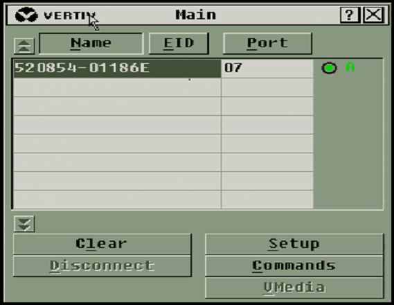
3.1.1 Viewing and selecting ports and devices
Use the OSCAR™ Main dialog box to view, configure and control devices in the switch system. View your
devices by name, port or by the unique EID number embedded in each IQ module.
In the following figure, the Port column indicates the ARI port to which a device is connected. If you tier a
switch from the main switch, creating another tier, the ARI port on the switch is listed first and is followed
by the switch port to which the device is connected.
Figure 3.1 OSCAR Interface Main Dialog Box
NOTE: You can press the Control , Alt or Shift keys twice within one second to launch the OSCAR
interface. You can use this key sequence when you see Print Screen throughout this chapter.
17Table 3.1 Main Dialog Box Functions
BUTTON FUNCTION
Name Name of device.
EID Unique EID in a module.
Port The port to which a device is connected.
Clear Clear all offline IQ modules.
Disconnect Disconnect the KVM session.
Setup Access the Setup dialog box and configure the OSCAR interface.
Commands Access the Commands dialog box.
VMedia Control virtual media connection.
3.1.2 Viewing switch system status
The status of devices in your system is indicated in the right column of the Main dialog box. The following
table describes the status symbols.
Vertiv™ | Avocent® AutoView™ 2108/2216/3108/3216 Switch Installer/User Guide
18Table 3.2 OSCAR Interface Status Symbols
SYMBOL DESCRIPTION
(Green circle) device connected, turned on and the IQ module is online.
Connected device is turned off or is not operating properly and the IQ module is offline.
Connected switch is online.
Connected switch is offline or not operating properly.
(Yellow circle) The designated IQ module is being upgraded. When this symbol displays, do not cycle power to the
switch or connected devices and do not disconnect the IQ module. Doing so can render the module permanently
inoperable and require the IQ module to be returned to the factory for repair.
(Green letter) IQ module is being accessed by the indicated user channel.
(Black letter) IQ module is blocked by the indicated user channel.
(Red letter) Smart card support is available.
3.1.3 Selecting devices
Use the Main dialog box to select a device. When you select a device, the switch reconfigures the local
keyboard and mouse to the settings for that device.
To select a device:
Double-click the device name, EID or port number.
or-
If the display order of your list is by port (the Port button is depressed), type the port number and press
Enter .
-or-
3 Local OSCAR™ User Interface 19If the display order of your list is by name or EID (the Name or EID button is depressed), type the first few
letters of the name of the device or the EID number to establish it as unique and press Enter.
To select the previous device:
Press Print Screen and then Backspace. This key combination toggles between the previous and current
connections.
To disconnect from a device:
Press Print Screen and then Alt+0 (zero). This leaves you in a free state, with no device selected. The
status flag on your desktop displays the word Free.
3.1.4 Soft switching
Soft switching is the ability to switch devices using a hotkey sequence. You can soft switch to a device by
pressing Print Screen and then depending on the method you’ve selected, typing the first few characters
of its name or number. If you have set a Screen Delay Time for the OSCAR™ interface and you press the
key sequences before that time has elapsed, the OSCAR interface is not displayed.
To soft switch to a device:
Press Print Screen, type the port number and the first few letters of the name of the device, to establish it
as unique and press Enter.
To switch back to the previous device, press Print Screen and then Backspace.
3.1.5 Navigating the OSCAR interface
The following table describes how to navigate the OSCAR™ interface using the keyboard and mouse.
Vertiv™ | Avocent® AutoView™ 2108/2216/3108/3216 Switch Installer/User Guide
20Table 3.3 OSCAR Interface Navigation Basics
KEYSTROKE FUNCTION
Print Screen,
Ctrl+Ctrl,
OSCAR interface activation sequence. By default, Print Screen and Ctrl+Ctrl are set as the OSCAR interface
Shift+Shift
activation options. Shift+Shift and Alt+Alt must be set within the OSCAR interface before use.
and/or
Alt+Alt
F1 Opens the Help window for the current dialog box.
Closes the current dialog box without saving changes and returns to the previous one. If the Main dialog box is
displayed, pressing Escape closes the OSCAR interface and displays a status flag if status flags are enabled. See
Escape
Commands Dialog Box Functions on page 26 for more information. In a message box, pressing Escape closes the
pop-up box and returns to the current dialog box.
Opens dialog boxes, selects or checks options and executes actions when used with underlined or other designated
Alt
letters.
Alt+X Closes current dialog box and returns to previous one.
Alt+O Selects the OK button, then returns to the previous dialog box.
Enter Completes a switch operation in the Main dialog box and exits the OSCAR interface.
Single-click, In a text box, single-clicking an entry and pressing Enter selects the text for editing and enables the left and right
Enter arrow keys to move the cursor. Press Enter again to quit the Edit mode.
Print Screen,
Toggles back to the previous selection.
Backspace
Print Screen,
Immediately turns on Screen Saver mode and prevents access to that specific console, if it is password protected.
Pause
Up/Down
Moves the cursor from line to line in lists.
Arrows
Right/Left
Moves the cursor between columns. When editing a text box, these keys move the cursor within the column.
Arrows
Page
Up/Page Pages up and down through names, ports and Help pages.
Down
Home/End Moves the cursor to the top or bottom of a list.
Backspace Erases characters in a text box.
3.1.6 Connecting local virtual media
You can connect virtual media directly to the switch using a USB port on the switch.
NOTE: All USB ports are assigned to a single virtual media session and cannot be independently
mapped.
To start a local virtual media session, complete the following steps:
1. Press Print Screen to start the OSCAR™ interface and open the Main window.
3 Local OSCAR™ User Interface 212. Connect to the device with which you want to establish a virtual media session.
3. Use the arrow keys to highlight the device name and press Enter.
4. Press Print Screen to start the OSCAR interface again. The Virtual Media window is displayed.
5. Select one or more of the following checkboxes:
• Locked - Select this checkbox to specify that when the user is disconnected from a
device, the virtual media is also disconnected.
• Reserve - Select this checkbox to specify that the virtual media connection can be
accessed only by your user name and that no other user can connect to that device. If
both Locked and Reserved are selected, the session is reserved.
• CD ROM - Select this checkbox to establish a virtual media CD connection to a device.
Clear this checkbox to end the connection.
• Mass Storage - Select this checkbox to establish a virtual media mass-storage connection
to a device. Clear this checkbox to end the connection.
• Write Access - Select this checkbox to enable the connected device to write data to the
virtual media during a virtual media session. Read access is always enabled during virtual
media sessions.
6. Click OK.
3.2 Setup Dialog Box Functions
You can configure your switch system from the Setup dialog box within the OSCAR™ interface. Select the
Names button when initially setting up your switch to identify devices by unique names. Select the other
setup features to manage routine tasks for your devices from the OSCAR interface menu. The following
table lists the functions accessed using each of the buttons in the Setup dialog box.
To access the OSCAR interface Setup dialog box, click Setup on the Main dialog box.
Vertiv™ | Avocent® AutoView™ 2108/2216/3108/3216 Switch Installer/User Guide
22Table 3.4 Setup Dialog Box Features
FEATURE PURPOSE
Change the Main dialog box list sorting option by toggling numerically between port number, EID number or
Menu alphabetically by name. Change the Screen Delay Time before the OSCAR interface displays after pressing Print Screen.
You can also change how the OSCAR interface activation sequence is invoked.
Security Set passwords to protect or restrict access or enable the window saver.
Devices Identify the appropriate number of ports on an attached tiered switch.
Names Identify devices by unique names.
Keyboard Set the keyboard country code value for the USB devices.
Network Choose your network speed, transmission mode and configuration.
Scan Set up a custom Scan pattern for multiple devices.
VMedia Set the behaviour of the switch during a virtual media session.
3.2.1 Changing the display behavior
Use the Menu dialog box to change the order of displayed devices, change how the OSCAR interface is
invoked or set a Screen Delay Time for the OSCAR interface. This setting alters how devices are displayed
in several dialog boxes, including the Main, Devices and Scan List boxes.
To access the OSCAR interface Menu dialog box, activate the OSCAR interface and click Setup - Menu in
the Main dialog box.
To choose the display order of devices:
1. Select Name to display devices alphabetically by name.
-or-
Select EID to display devices numerically by EID number.
-or-
Select Port to display devices numerically by port number.
2. Click OK.
Depending on the display method selected, the corresponding button is depressed in the Main dialog
box.
To change how the OSCAR interface is invoked:
1. Select the checkbox next to one of the listed methods.
2. Click OK.
3 Local OSCAR™ User Interface 23To set a Screen Delay Time for the OSCAR™ interface:
1. Type in the number of seconds (0-9) to delay the OSCAR interface display after you press
Print Screen. Enter 0 to launch the OSCAR interface with no delay.
2. Click OK.
Setting a Screen Delay Time enables you to complete a soft switch without the OSCAR interface. To
perform a soft switch, see Soft switching on page 20.
3.2.2 Controlling the status flag
The status flag displays on your desktop and shows the name or EID number of the selected device or the
status of the selected port. Use the Flag dialog box to configure the flag to display by device name or EID
number or to change the flag color, opacity, display time and location on the desktop.
To access the OSCAR interface Flag dialog box:
Activate the OSCAR interface and click Setup - Flag to open the Flag dialog box.
To determine how the status flag is displayed:
1. Select Name or EID to determine what information is displayed. The following interface Status
Flags are available:
• Flag description
• Flag type by name
• Flag type by EID number
• Flag indicating that you have been disconnected from all systems
2. Select Displayed to activate the flag display. After a switch, the flag remains on the window
until you switch to another device. Selecting Timed causes the flag to display for five seconds
when a switch is made and then disappears.
3. Select a flag color under Display Color. The following flag colors are available:
• Flag 1 - Gray flag with black text
• Flag 2 - White flag with red text
• Flag 3 - White flag with blue text
• Flag 4 - White flag with violet text
4. In Display Mode, select Opaque for a solid color flag or Transparent to see the desktop through
the flag.
5. To position the status flag on the desktop:
a. Click Set Position to gain access to the position flag window.
b. Left-click on the title bar and drag it to the desired location.
c. Right-click to return to the Flag dialog box.
NOTE: Changes made to the flag position are not saved until you click OK in the Flag dialog box.
Vertiv™ | Avocent® AutoView™ 2108/2216/3108/3216 Switch Installer/User Guide
246. Click OK to save settings.
-or-
Click X to exit without saving changes.
3.2.3 Setting the keyboard country code
NOTE: Using a keyboard code that supports a language different from that of your switch firmware
causes incorrect keyboard mapping.
By default, the switch sends the US keyboard country code to USB modules attached to devices and the
code is applied to the devices when they are turned on or rebooted. Codes are then stored in the IQ
module. Issues can arise when you use the US keyboard country code with a keyboard of another country.
For example, the Z key on a US keyboard is in the same location as the Y key on a German keyboard. The
Keyboard dialog box enables you to send a different keyboard country code than the default US setting.
The specified country code is sent to all devices attached to the switch when they are turned on or
rebooted and the new code is stored in the IQ module.
NOTE: If an IQ module is moved to a different device, the keyboard country code needs to be reset.
3.2.4 Assigning device types
To access the OSCAR interface Devices dialog box:
Activate the OSCAR™ interface and click Setup - Devices to open the Devices dialog box.
NOTE: The Modify button is available only if a configurable switch is selected.
When the switch discovers a tiered switch, the numbering format changes from switch port to [switch
port]-[switch port] to accommodate each device under that switch.
For example, if a switch is connected to console switch port 6, each device connected to it would be
numbered sequentially. The device using console switch port 6 and switch port 1 is 06-01. The device
using console switch port 6 and switch port 2 is 06-02 and so on.
To assign a device type:
1. In the Devices dialog box, select the desired port number.
2. Click Modify to open the Device Modify dialog box.
3. Choose the number of ports supported by your switch and click OK.
4. Repeat steps 1-3 for each port requiring a device type to be assigned.
3.2.5 Assigning device names
Use the Names dialog box to identify devices by name rather than by port number. The Names list is
always sorted by port order. You can toggle between displaying the name or the EID number of each IQ
module, so even if you move the IQ module/device to another port, the name and configuration is
recognized by the switch.
3 Local OSCAR™ User Interface 25NOTE: When it is initially connected, a device does not appear in the Names list until it is turned on.
Once an initial connection is made, it appears in the Names list even when turned off.
To access the OSCAR interface Names dialog box, activate the OSCAR interface and click Setup - Names.
NOTE: If new IQ modules are discovered by the switch, the on-window list is automatically updated.
The mouse cursor changes into an hourglass during the update. No mouse or keyboard input is
accepted until the list update is complete.
To assign names to devices:
1. In the Names dialog box, select a device name or port number and click Modify to open the
Name Modify dialog box.
2. Type a name in the New Name box. Names of devices can contain all printable characters.
3. Click OK to assign the new name.
4. Repeat steps 1-3 for each device in the system.
5. Click OK in the Names dialog box to save your changes.
-or-
Click X or press Escape to exit the dialog box without saving changes.
3.2.6 Configuring network settings
Use the Network dialog box to set the Network Speed, Transmission Mode and Network Configuration
feature.
To change network settings:
1. If the OSCAR™ interface is not open, press Print Screen to open the Main dialog box.
2. Click Setup - Network to open the Network dialog box.
3. Make desired changes and click OK to confirm or click X to exit without saving.
NOTE: Changing the network settings causes the switch to reboot.
4. Click OK in the Devices dialog box to save settings.
NOTE: Changes made in the Device Modify dialog box are not saved to the switch until you click OK in
the Device Modify dialog box.
NOTE: Changes made in the Name Modify dialog box are not saved to the switch until you click OK in
the Names dialog box.
NOTE: If an IQ module has not been assigned a name, the EID is used as the default name.
3.3 Commands Dialog Box Functions
From the OSCAR interface Commands dialog box, you can manage your switch system and user
connections, enable the Scan mode and update your firmware.
Vertiv™ | Avocent® AutoView™ 2108/2216/3108/3216 Switch Installer/User Guide
26Table 3.5 Commands to Manage Routine Tasks for Your Devices
FEATURES PURPOSE
Begin scanning your devices. Set up a device list to scan in the Setup dialog box. You must have at least two devices
Scan Enable
selected in the Setup - Scan List menu to enable device scanning.
User Status View and disconnect users.
IQ Module
Display the currently available firmware for each type of IQ module.
Status
Display
View version information for the switch as well as view and upgrade firmware for individual IQ modules.
Versions
Display
View current configuration parameters.
Config
Device
Re-establish operation of the keyboard and mouse on the local port.
Reset
To access the OSCAR™ Commands dialog box:
Activate the OSCAR™ interface and click Commands to open the dialog box.
3.3.1 Selecting devices for scan mode
The Scan dialog box allows the local user to define a custom list of devices to include while in Scan mode
and the number of seconds to display each device. The creation of the Scan list does not start Scan mode.
You must enable Scan mode using the Scan Enable checkbox on the Commands dialog box. The Scan list
is displayed in the manner set from the Menu dialog box. It can be changed in the Scan dialog box to sort
either by name, EID or port by choosing one of the buttons. If a device on the list is unavailable, it is
skipped. Watch mode views a device unless a conflicting network user blocks the path to that device. If a
conflict is detected in Watch mode (or the device is unavailable), the device to be viewed is skipped.
To add devices to the Scan list:
1. Activate the OSCAR interface and click Setup - Scan to open the Scan dialog box.
2. The dialog box contains a listing of all devices attached to your switch. Click the checkbox to
the right of the device, double-click on the desired entry or highlight the device and click the
Add/Remove button to toggle the Scan checkbox setting. You can select up to 100 devices for
inclusion in the Scan list.
NOTE: Click the Clear button to remove all devices from the Scan list.
3. In the Time field, type the number of seconds (from 3 - 255) to display each device while
scanning. The default is 15 seconds per device.
4. Click OK.
NOTE: The order in which the devices appear in the Scan dialog box is based on the order in which they
were selected. Scanning a single device multiple times during a loop is not supported. Scan time must
be the same for all devices.
3 Local OSCAR™ User Interface 273.3.2 Enabling or disabling scan mode
To start the Scan mode:
1. Activate the OSCAR interface and click Commands.
2. In the Commands dialog box, select Scan Enable in the Commands dialog box.
3. After scanning begins, click X to close the Commands dialog box.
To cancel Scan mode:
If the OSCAR interface is open, select a device.
-or-
If the OSCAR interface is not open, move the mouse or press any key on the keyboard. Scanning stops at
the currently selected device.
-or-
From the Commands dialog box, clear the Scan Enable checkbox.
3.3.3 Viewing and disconnecting user connections
You can view and disconnect users through the User Status dialog box. The username (U) and server (S)
is always displayed when connected to a device (local or remote). You can display either the device name
or EID number to which a user is connected. If there is no user currently connected to a channel, the
username and device fields are blank.
To view current user connections, activate the OSCAR™ interface and click Commands > User Status to
open the User Status dialog box.
To disconnect a user:
1. On the User Status dialog box, click the letter corresponding to the user to disconnect.
2. In the Disconnect dialog box, click Disconnect to disconnect the user and return to the User
Status dialog box.
-or-
Click X or press Escape to exit the dialog box without disconnecting a user.
3.3.4 Displaying version information and upgrading firmware
For troubleshooting and support, the OSCAR interface enables you to display the version number of the
switch firmware and any auxiliary devices connected to the switch, as well as upgrade your firmware for
optimum performance.
Vertiv™ | Avocent® AutoView™ 2108/2216/3108/3216 Switch Installer/User Guide
28To display version information and upgrade firmware:
1. Activate the OSCAR interface and click Commands - Display Versions. The top half of the box
lists the subsystem version in the switch. The lower half displays the current IP address, Mask,
MAC and EID.
2. If you want to upgrade the firmware, click Upgrade and then click OK to open the download
box. You are prompted for an FTP or TFTP device IP address and the related information.
3. Click Download. After the firmware is downloaded, the Upgrade dialog box appears.
4. Click the Upgrade button.
NOTE: The switch reboots when the upgrade is complete.
To upgrade individual IQ modules:
1. Click the IQ button to view individual IQ module version information.
2. Select the IQ button to view and click the Version button.
3. Click the Load Firmware button.
4. Click OK to initiate the upgrade and return to the Status dialog box.
NOTE: During an upgrade, the IQ module status indicator in the Main dialog box is yellow. The IQ
modules are unavailable when an upgrade is in progress. When an upgrade is initiated, any current
connection to the device using the IQ module is terminated.
To simultaneously upgrade multiple IQ modules:
1. Activate the OSCAR interface, click Commands - IQ Status and click one or more types of IQ
modules to upgrade.
2. Click Upgrade.
NOTE: When the Enable IQ Auto update option is enabled in the IQ Status dialog box, IQ module
firmware is automatically upgraded when the switch firmware is upgraded or when a new IQ module is
discovered by the switch after a firmware upgrade. IQ modules that have already been discovered but
which are not attached to the switch during the firmware upgrade must be upgraded manually.
3. In the IQ Upgrade dialog box, click OK to initiate the upgrade and return to the IQ Status dialog
box.
To return an IQ module to factory default status:
1. Click IQ in the Version dialog box.
2. Select an IQ module, then click Decommission.
3. Click OK to restore factory defaults. The IQ module goes offline briefly and returns.
- or-
Click X or press Escape to cancel the operation.
4. Click X to close the IQ Select dialog box.
3 Local OSCAR™ User Interface 29This page intentionally left blank
Vertiv™ | Avocent® AutoView™ 2108/2216/3108/3216 Switch Installer/User Guide
304 OBWI OPERATION
The OBWI for the AutoView switch is a remote, web browser-based user interface. For details on setting up
your system, see Connecting the AutoView™ Switch Hardware on page 5. The following table lists the
operating systems and browsers that are supported by the OBWI. Make sure that you are using the latest
version of your Web browser.
Table 4.1 Operating Systems Supported by the OBWI
BROWSER
OPERATING SYSTEM
MICROSOFT® INTERNET FIREFOX VERSION GOOGLE CHROME
EXPLORER® VERSION 9.0 10 AND LATER VERSION 19 AND LATER
Microsoft Windows Server® 2003 Standard,
Yes Yes Yes
Enterprise or Web Edition
Microsoft Windows XP Home Edition or
Yes Yes Yes
Professional
Microsoft Windows 7 or 8 Yes Yes Yes
Microsoft Windows Server® 2012 Yes Yes Yes
Microsoft Windows 2008 Yes Yes Yes
Red Hat Enterprise Linux® 5 and 6 No Yes No
Canonical Ubuntu 12.04 No Yes No
Sun Solaris® 10 and 11 No Yes No
Novell SUSE Linux Enterprise 10 and 11 No Yes No
Apple Mac OS X Tiber 10.4+ No Yes No
To log in to the switch OBWI:
1. Launch a web browser.
2. In the address field of the browser, enter the IP address or host name assigned to the switch
you wish to access. Use https://xxx.xx.xx.xx or https://hostname as the format.
NOTE: If using IPv6 mode, you must include square brackets around the IP address. Use https://
[NOTE: Using the OBWI requires using Java Runtime Environment (JRE) version 1.6.0_11 or higher.
NOTE: Once you have logged in to the OBWI, you do not have to log in again when launching new
sessions unless you have logged out or your session has exceeded the inactivity timeout specified by
the administrator.
4.1 Using the OBWI
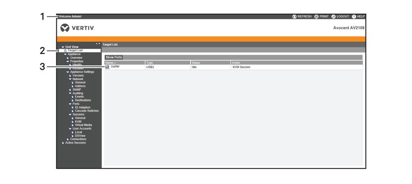
After you have been authenticated, the user interface appears. You can view, access and manage your
switch, as well as specify system settings and change profile settings. The following figure shows the user
interface window areas. The window descriptions are provided in the following table.
Figure 4.1 OBWI Window
Table 4.2 Descriptions for the OBWI
ITEM NAME DESCRIPTION
Use the top option bar to contact Technical Support, view the software general
1 Top option bar
information, log out of an OBWI session or access the Help tool
Use the side navigation bar to select the information to be displayed. You can use the
2 Side navigation bar side navigation bar to display windows in which you can specify settings or perform
operations.
3 Content area Use the content area to display or make changes to the switch OBWI system.
4.2 Viewing System Information
You can view switch and target device information from the following windows in the user interface.
Vertiv™ | Avocent® AutoView™ 2108/2216/3108/3216 Switch Installer/User Guide
32Table 4.3 System Information
CATEGORY SELECT THIS: TO VIEW THIS:
List of connected devices, as well as the name, type, status and action of each device. Click
Unit View - Target
Target Devices on a target device to view the following information: name, type, EID, available session
Devices
option and the connection path.
Unit View - Name, type and the switch tools (Maintenance-Overview/Reboot/Reset and Upgrade,
AutoView switch
Appliance - Tools Certificates and Trap MIB).
Unit View -
Configuration and User Database for the switch.
Appliance - Files
Unit View -
Appliance - Part number, serial number and status of the RAK-key (default setting is disabled).
Properties - NOTE: RAK-key installation is only applicable for the 2108/2216 switch models.
Identity
Unit View -
Appliance -
Site, department and location of each unit.
Properties -
Location
Unit View -
Appliance
Current application, boot, build, hardware, UART and video ASIC versions.
Settings -
Versions
Unit View -
Appliance
Network address, LAN speed and web server ports.
Settings -
Network
Unit View -
System description, SNMP setting, contact, read/write and trap settings and designations
Appliance
for allowed managers.
Settings - SNMP
Unit View -
Appliance
Events list and status and SNMP trap destinations.
Settings -
Auditing
Unit View -
Status, EID, name, port, application and interface type for each IQ adaptor; name, port,
Appliance
type, channels and status for each tiered switch.
Settings - Ports
Unit View -
General session timeout and sharing details; KVM encryption levels and keyboard
Appliance
language; virtual media settings, drive mappings, encryption level and IQ adaptor access.
Settings Sessions
4 OBWI Operation 33Table 4.3 System Information (continued)
CATEGORY SELECT THIS: TO VIEW THIS:
Unit View - Security and user lock-out for the local account; authentication server assignments for
Appliance - User DSView management software and override admin username and password in case of a
Accounts failed operation.
Unit View -
Appliance - Connection path name and type.
Connections
Active Sessions Server, owner, remote host, duration and type of each active session.
NOTE: IQ adaptor and IQ module are used interchangeably. In the OSCAR interface, IQ module is the
term used. In the OBWI, IQ adaptor is the term used.
4.3 Generating a Certificate
A web certificate allows you to access the OBWI without having to acknowledge the switch as a trusted
web device each time you access it. Using the Install Web Certificate window, you can generate a new self-
signed openssl or upload a certificate. Uploaded certificates must be in OpenSSL PEM format with an
unencrypted private key.
To install a web certificate:
1. From the side navigation bar, select Unit View - Appliance - Overview.
2. Click Manage Appliance Web Certificate.
3. Click Update.
4. Select the Generate a new Self-Signed Certificate radio button and enter the following fields:
• Common Name: your name. (Since this is your root certificate, use an appropriate name
such as, "Company_Name Certificate Authority.")
• Organization: organization unit name (marketing, for example).
• City or Locality: the city where your organization is located.
• State or Province: the unabbreviated state or province where your organization is located.
• Country: the two-letter ISO abbreviation for your country.
• Email Address: the email address for the Certificate Authority (CA) to contact.
5. Click Generate to create the certificate.
To upload a new certificate:
1. Select the Upload a New Certificate radio button.
2. Select the method (Filesystem, TFTP, FTP or HTTP).
3. Click Browse to search for the certificate or enter the certificate filename.
4. Select Install. Close the web browser, then launch the OBWI again for the same IP address.
NOTE: If importing a company certificate file, it can take up to 30 seconds for the OBWI to launch.
Vertiv™ | Avocent® AutoView™ 2108/2216/3108/3216 Switch Installer/User Guide
345. When prompted, click to view the certificate and follow the instructions to import the
certificate into the Root Certificate Authority folder. After the certificate is stored, the user
should not see the certificate warning.
4.4 Tools - Rebooting and Upgrading
From the Unit View - Appliance - Overview window, you can view the switch name and type. You can also
perform the following tasks.
4.4.1 Rebooting the switch
To reboot the switch:
1. From the side navigation bar, click Unit View - Appliance - Overview to open the Unit
Maintenance window.
2. Click the Reboot button.
3. A dialog box appears, warning you that all active sessions is disconnected. Click the OK button.
NOTE: If you are using the local UI, the window is blank while the switch reboots. If you are using the
remote OBWI, a message indicates that the interface is waiting on the switch to complete the reboot.
4.4.2 Upgrading switch firmware
You can update your switch with the latest firmware available.
After the memory is reprogrammed with the upgrade, the switch performs a soft reset, which terminates
all IQ adaptor sessions. A target device experiencing an IQ adaptor firmware update can not display or
can display as disconnected. The target device appears normally when the update is completed.
Attention: Disconnecting an IQ adaptor during a firmware update or cycling power to the target device
renders the module inoperable and requires the IQ adaptor to be returned to the factory for repair.
To upgrade the switch firmware:
1. From the side navigation bar, click Unit View - Appliance - Overview to open the Unit
Maintenance window.
2. Click Upgrade Firmware.
3. Select one of the following methods to load the firmware file: Filesystem, TFTP, FTP or HTTP.
NOTE: The Filesystem option is only available on the remote OBWI.
4. If you selected Filesystem, select Browse to specify the location of the firmware upgrade file.
-or-
If you selected TFTP, enter the server IP address and firmware file you wish to load.
-or-
4 OBWI Operation 35You can also read