MRD 2600 Modular Receiver - User Manual - Sencore
←
→
Page content transcription
If your browser does not render page correctly, please read the page content below

MRD 2600
        Modular Receiver

        User Manual

                                                         November 2020
8104Q                 www.sencore.com | 1.605.978.4600     Revision 1.17
MRD 2600 – User Manual

Copyright
© 2020 Sencore, Inc. All rights reserved.
3200 Sencore Drive, Sioux Falls, SD USA
www.sencore.com
This publication contains confidential, proprietary, and trade secret information. No part of this document may
be copied, photocopied, reproduced, translated, or reduced to any machine-readable or electronic format
without prior written permission from Sencore. Information in this document is subject to change without notice
and Sencore Inc. assumes no responsibility or liability for any errors or inaccuracies. Sencore, Sencore Inc,
and the Sencore logo are trademarks or registered trademarks in the United States and other countries. All
other products or services mentioned in this document are identified by the trademarks, service marks, or
product names as designated by the companies who market those products. Inquiries should be made directly
to those companies. This document may also have links to third-party web pages that are beyond the control
of Sencore. The presence of such links does not imply that Sencore endorses or recommends the content on
those pages. Sencore acknowledges the use of third-party open source software and licenses in some
Sencore products. This freely available source code can be obtained by contacting Sencore Inc.

About Sencore
Sencore is an engineering leader in the development of high-quality signal transmission solutions for the
broadcast, cable, satellite, IPTV, telecommunications, and professional audio/video markets. The
company’s world-class portfolio includes video delivery products, system monitoring and analysis solutions,
and test and measurement equipment, all designed to support system interoperability and backed by best-
in-class customer support. Sencore meets the rapidly changing needs of modern media by ensuring
efficient delivery of high-quality video from the source to the home. For more information, visit
www.sencore.com.

Page 2 (86)
MRD 2600 – User Manual

Revision History

       Date      Version    Description                             Author
    06/10/2013     1.0     Initial Release (1.2.0 software)   NDM
    08/30/2013     1.1     Update for ver. 1.2.0 Release      NGJ
    11/21/2013     1.2     Update for ver. 1.3.0 Release      NGJ
     3/11/2014     1.3     Update for ver. 1.4.0 Release      CDP
     5/14/2014     1.4     Update for ver. 2.0.0 Release      CDP
     9/18/2014     1.5     Update for ver. 2.1.0 Release      CDP
     3/1/2015      1.6     Update for ver. 2.2.2              JDF
     3/12/2015     1.7     Update for ver. 2.3.0              CDP
     7/8/2015      1.8     Update for ver. 2.4.0              CDP
    10/21/2015     1.9     Update for ver. 2.5.0              CDP
     3/1/2016     1.10     Update for ver. 3.0.0              CDP
     6/6/2016     1.11     Update for ver. 3.1.0              CDP
     9/28/2016    1.12     Update for ver. 3.2.0              CDP
      4/07/17     1.13     Update for 3.3.0                   ACD
     1/27/2020    1.14     Appending to S2X Module Specs      BCR
    07/21/2020    1.15     Update for 4.2.3 Release           RAG
    09/02/2020    1.16     Updated screenshots for new GUI    RAG
    10/12/2020    1.17     Update for 4.3.0 Release           JDN

  Page 3 (86)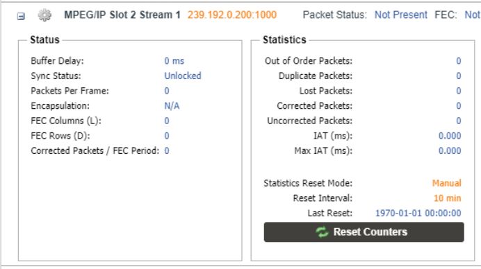
MRD 2600 – User Manual
Safety Instructions
Read these instructions
Keep these instructions
Heed all warnings
Follow all instructions
Do not use this apparatus near water
Clean only with dry cloth
Do not block any ventilation openings. Install in accordance with the
manufacturer’s instructions
Do not install near any heat sources such as radiators, heat registers, stoves, or
other apparatus (including amplifiers) that produce heat
Do not defeat the safety purpose of the polarized or grounding-type plug. A
polarized plug has two blades with one wider than the other. A grounding type
plug has two blades and a third grounding prong. The wide blade or the third
prong is provided for your safety. If the provided plug does not fit into your outlet,
consult an electrician for replacement of the obsolete outlet.
Protect the power cord from being walked on or pinched particularly at plugs,
convenience receptacles, and the point where they exit from the apparatus.
Only use attachments/accessories specified by the manufacturer.
Unplug this apparatus during lightning storms or when unused for long periods of
time.
Refer all servicing to qualified service personnel. Servicing is required when the
apparatus has been damaged in any way, such as power-supply cord or plug is
damaged, liquid has been spilled or objects have fallen into the apparatus, the
apparatus has been exposed to rain or moisture, does not operate normally, or
has been dropped.
Do not expose this apparatus to dripping or splashing and ensure that no objects
filled with liquids, such as vases, are placed on the apparatus.
To completely disconnect this apparatus from the AC Mains, disconnect the
power supply cord plug from the AC receptacle.
The mains plug of the power supply cord shall remain readily operable.
Damage Requiring Service: Unplug this product from the wall outlet and refer
servicing to qualified service personnel under the following conditions:
o When the power-supply cord or plug is damaged.
o If liquid has been spilled, or objects have fallen into the product.
o If the product has been exposed to rain or water.
o If the product does not operate normally by following the operating
instructions. Adjust only those controls that are covered by the
operating instructions as an improper adjustment of the controls may
result in damage and will often require extensive work by a qualified
technician to restore the product to its normal operation.
o If the product has been dropped or damaged in any way.
o The product exhibits a distinct change in performance.
Replacement Parts: When replacement parts are required, be sure the service
technician uses replacement parts specified by Sencore, or parts having the
Page 4 (86)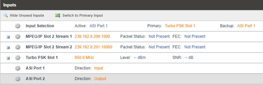
MRD 2600 – User Manual
same operating characteristics as the original parts. Unauthorized part
substitutions made may result in fire, electric shock or other hazards.
SAFETY PRECAUTIONS
There is always a danger present when using electronic equipment.
Unexpected high voltages can be present at unusual locations in defective
equipment and signal distribution systems. Become familiar with the equipment
that you are working with and observe the following safety precautions.
Every precaution has been taken in the design of your MRD 2600 to ensure that
it is as safe as possible. However, safe operation depends on you the operator.
Always be sure your equipment is in good working order. Ensure that all points
of connection are secure to the chassis and that protective covers are in place
and secured with fasteners.
Never work alone when working in hazardous conditions. Always have another
person close by in case of an accident.
Always refer to the manual for safe operation. If you have a question about the
application or operation call Sencore for assistance.
WARNING – To reduce the risk of fire or electrical shock never allow your
equipment to be exposed to water, rain or high moisture environments. If exposed
to a liquid, remove power safely (at the breaker) and send your equipment to be
serviced by a qualified technician.
To reduce the risk of shock the MRD 2600 must be connected to a mains socket
outlet with a protective earthing connection.
For the MRD 2600 the mains plug is the main disconnect and should remain readily
accessible and operable at all times.
The MRD 2600 is equipped with an internal system battery. The MRD 2600 must
be sent to Sencore service for replacement of this battery.
When installing the MRD 2600 utilizing the DC power supply, the power supply
MUST be used in conjunction with an over-current protective device rated at 50 V,
5 A, type: Slow-blo, as part of battery-supply circuit.
To reduce the risk of shock and damage to equipment, it is recommended that the
chassis grounding screw located on the rear of the MRD 2600 – be connected to
the installation’s rack, the vehicle’s chassis, the battery’s negative terminal, and/or
earth ground.
CAUTION – Danger of explosion if battery is incorrectly replaced. Replace only
with the same or equivalent type.
Page 5 (86)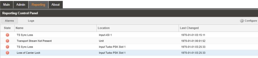
MRD 2600 – User Manual

FCC Class A Information
The MRD 2600 has been tested and found to comply with the limits for a Class A digital
device, pursuant to Part 15 of the FCC Rules. These limits are designed to provide
reasonable protection against harmful interference when the equipment is operated in a
commercial environment. This equipment generates, uses, and can radiate radio
frequency energy and, if not installed and used in accordance with the instructions, may
cause harmful interference to radio communications. Operation of this equipment in a
residential area is likely to cause harmful interference in which case the user will be
required to correct the interference at his or her own expense.
Shielded cables must be used with this unit to ensure compliance with the Class A FCC
limits.

   Warning: Changes or modifications to this unit not expressly approved by the
party responsible for compliance could void the user’s authority to operate the
equipment.

Page 6 (86)

MRD 2600 – User Manual

Package Contents
The following is a list of the items that are included along with the MRD 2600:

   1. Declaration of Conformity
   2. AC Power Cable
   3. Quick Start Guide

Note: If any option cables were ordered with the MRD 2600 they will be included in the
     box as well.

If any of these items were omitted from the packaging of the MRD 2600 please call 1-800-
SENCORE to obtain a replacement. Manuals for Sencore products can be downloaded at
www.sencore.com

 1) Declaration of Conformity   2) AC Power Cable              3) Quick Start Guide

Page 7 (86)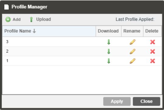
MRD 2600 – User Manual

Table of Contents

Section 1 Overview ........................................................................................... 10
     1.1       Product Introduction ...................................................................................................11
     1.2       Front Panel Overview ................................................................................................11
     1.3       Rear Panel Overview .................................................................................................11
     1.4       Cooling .......................................................................................................................12
     1.5       Rack Information ........................................................................................................12
Section 2 Installation ........................................................................................ 13
     2.1       Rack Installation ........................................................................................................14
     2.2       Power Connection .....................................................................................................14
     2.3       AC Power Connection ...............................................................................................14
     2.4       AC Dual Redundant Power Connection (optional) ....................................................15
     2.5       DC Power Connection ...............................................................................................15
     2.6       Maintenance ..............................................................................................................15
     2.7       Network Setup via Front Panel ..................................................................................15
Section 3 Operating the Front Panel ............................................................... 18
     3.1       MRD 2600 Front Panel Overview ..............................................................................19
Section 4 Operating the Web Interface ........................................................... 20
     4.1       MRD 2600 Web Interface Overview ..........................................................................21
                 Logging into the MRD 2600 Web Interface ..........................................................21
                 Hiding Unused Inputs ...........................................................................................21
                 Buttons and Status Indicators...............................................................................21
                 Drag and Drop Menus ..........................................................................................22
     4.2       Main Panel .................................................................................................................23
                 Configuring Active Inputs......................................................................................24
                 Configuring ASI Input ...........................................................................................25
                 Configuring MPEG/IP Input ..................................................................................26
                 Configuring DVB-S/S2/S2X Input .........................................................................29
                 Configuring DVB-S/S2 Input .................................................................................31
                 Configuring 8VSB/QAM Input ...............................................................................33
                 Configuring Turbo PSK Input ...............................................................................34
                 Configuring DVB-T2/C2/ISDB-T Input ..................................................................36
                 Configuring DVB-CI Descrambling .......................................................................38
                 Configuring BISS Descrambling ...........................................................................40
                 PID Filter ...............................................................................................................42
                 Configuring ASI Output .........................................................................................43
                 Configuring the MPEG/IP Outputs .......................................................................44
                 Configuring the MPEG/IP MPE Outputs ...............................................................47
                 Viewing PSIP Information .....................................................................................49
     4.3       Admin Panel ..............................................................................................................50
                 Changing Unit Password ......................................................................................50
                 Profiles ..................................................................................................................51
                 General Settings ...................................................................................................52
                 Unit Network Configuration...................................................................................52
                 TACACS+ Configuration ......................................................................................53
                 MPEG/IP Network Configuration ..........................................................................54
                 Licensing...............................................................................................................56
                 Date/Time .............................................................................................................56
                 Configuring SNMP ................................................................................................57
                 Syslog ...................................................................................................................59

Page 8 (86)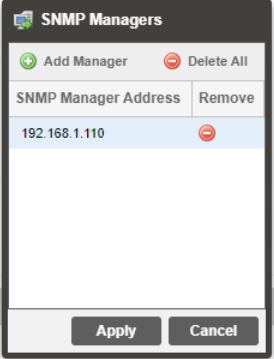
MRD 2600 – User Manual

                In-Band Control ....................................................................................................60
                Updating the MRD 2600 .......................................................................................61
                Reboot Unit ...........................................................................................................62
                Reset Defaults ......................................................................................................62
     4.4      Reporting Panel .........................................................................................................63
                Active Alarms ........................................................................................................63
                Event Logs ............................................................................................................64
                Configuring the Logs ............................................................................................65
     4.5      About Panel ...............................................................................................................67
Section 5 Appendices....................................................................................... 68
               – Acronyms and Glossary .................................................... 69
               – Error and Event List ........................................................... 72
               – Specifications ..................................................................... 74
               – Pinouts for Relay Connectors ........................................... 82
               – Open Source Software....................................................... 83
               – Warranty ............................................................................. 85
               – Support and Contact Information ..................................... 85

Page 9 (86)
MRD 2600 – User Manual
Section 1 Overview
Introduction
This section includes the following topics:
1.1 Product Introduction ...................................................................................................11
1.2 Front Panel Overview ................................................................................................11
1.3 Rear Panel Overview .................................................................................................11
1.4 Cooling .......................................................................................................................12
1.5 Rack Information ........................................................................................................12
Page 10 (86)MRD 2600 – User Manual
1.1 Product Introduction
The MRD 2600 is a Modular Receiver used as a turnaround product capable of receiving
a transport stream from the following interface types:
1) ASI
2) IP
3) DVB-S/S2
4) 8VSB
and converting it to ASI and/or IP out.
The MRD2600 also has the ability to descramble BISS and DVB-CI scrambling (a CAM
module needs to be purchased to descramble DVB-CI). This manual describes how to
install, configure, and operate the MRD 2600 Modular Receiver. It is written for
professional operators of video distribution systems and assumes a prerequisite level of
technical knowledge.
The MRD 2600 is controllable through the web interface, front panel, or SNMP to perform
tasks such as setup, monitoring, and troubleshooting.
Supported WEB interface browsers include:
- Internet Explorer 7 & above
- Mozilla Firefox 3.5 & above
1.2 Front Panel Overview
The MRD 2600 can be controlled from the front panel using the LCD screen and buttons
that are shown below. A detailed description of using the front panel can found in
Section 3.1. All hardware listed below comes standard except for the DVB-CI slots which
are a factory installed option.
1 4 5
2 3 3
6
3
3
3
1. LCD screen
2. Input Indicator
3. Error Indicator
4. Up, Down, Left, Right buttons
5. Back and Enter Buttons
6. 2x DVB-CI Slots (Factory Option)
1.3 Rear Panel Overview
The MRD 2600 comes standard with all of the hardware listed below except where noted
as a factory installed option. The three option cards available for the MRD 2600 are the
Quad Input DVB-S/S2 card, dual port MPEG/IP Input/Output card, and VSB/QAM
receive card. ASI is the standard input on all MRD 2600 units.
5 1
7 1 3 Z 6
2 4 1
1 1 1
Z Z
Z Z
Page 11 (86)MRD 2600 – User Manual
1
1. RJ45 Management Port Z
2. Relay Output Connector 1
3. ASI I/O Connectors Z
4. Option Card Slot #1 (factory installed)
5. Option Card Slot #2 (factory Installed) 1
6. Chassis ground Z
7. Optional Dual Power Supply
1.4 Cooling
The MRD 2600 is cooled via forced induction through the front of the unit and
exhausted through the vents in the rear of the chassis. The MRD 2600 is equipped
with a temperature controlled status indicator. If the temperature in the inside of the
unit exceeds 60° C the red “Error” text will illuminate on the front panel and a
description of the error will appear in the “Error List.”
1.5 Rack Information
The MRD 2600 is intended to be mounted in a standard 19” rack. It occupies 1RU of
rack space and the connections are all on the rear of the unit.
Page 12 (86)MRD 2600 – User Manual
Section 2 Installation
Introduction
This section includes the following topics:
2.1 Rack Installation ........................................................................................................14
2.2 Power Connection .....................................................................................................14
2.3 AC Power Connection ...............................................................................................14
2.4 AC Dual Redundant Power Connection (optional) ....................................................15
2.5 DC Power Connection ...............................................................................................15
2.6 Maintenance ..............................................................................................................15
2.7 Network Setup via Front Panel ..................................................................................15
Page 13 (86)MRD 2600 – User Manual
2.1 Rack Installation
To install the MRD 2600 into a rack use the following steps:
1. Determine the desired position in the rack for the MRD
2600 making sure that the air intake on the front of the
unit and the exhausts on the sides of the unit will not be
obstructed.
2. Insert the rack mount clips into place over the
mounting holes in the rack.
3. Slide the MRD 2600 into position in the rack.
4. Secure the MRD 2600 to the rack by installing the four
supplied screws through the front mounting holes and
tightening.
5. If needed, secure a grounding wire use the grounding
location on the rear panel of the MRD 2600. See
Section 1.3 for grounding location.
2.2 Power Connection
Using the proper power connections is vital to the safe operation of the MRD 2600.
Only use the supplied 3-prong power connector or one with equal specifications.
NEVER tamper with or remove the 3rd – prong grounding pin. This could cause
damage to the MRD 2600, personnel, or property.
2.3 AC Power Connection
The MRD 2600 is intended for use on either 120V or 240V systems. The power supply
will automatically detect the system it is connected to. To hook up the power use the
following steps:
1. Locate the AC power cord that was included with the MRD 2600.
2. Plug the female end of the power cord (end with no prongs) into the back of the
unit.
3. Locate a protected outlet (usually inside of the rack) to plug the male end of the
power cable into.
Page 14 (86)MRD 2600 – User Manual
2.4 AC Dual Redundant Power Connection (optional)
The Dual Redundant option allows the MRD 2600 to be powered by two separate
supplies either operating 120V or 240V systems. The power supply will automatically
detect the system it is connected to. To hook up the power use the following steps:
1. Locate the AC power cord that was included with the MRD 2600.
2. Plug the female end of the power cord (end with no prongs) into the back of the
unit.
3. Locate a protected outlet (usually inside of the rack) to plug the male end of the
power cable into.
2.5 DC Power Connection
The MRD 2600 with the DC chassis option is intended for use on 48V DC systems. A
power cable is not included for this option. In order to apply power to the unit in this
configuration, simply connect the screw terminals on rear of the unit to the rack’s DC
power rails.
Be sure that the power source and cable is used in conjunction with an over-current
protective device rated at 50V, 5A, type: Slow-blo fuse as part of battery-supply circuit.
Also, to reduce the risk of shock and damage to equipment, it is recommended that
the chassis grounding screw (1.3) located on the rear of the MRD 2600 – be connected
to the installation’s rack, battery negative terminal, and/or earth ground.
2.6 Maintenance
The MRD 2600 is virtually a maintenance-free piece of equipment. There are no user
serviceable parts on the inside of the unit
2.7 Network Setup via Front Panel
The MRD 2600 can be setup on a network connection to allow remote management and
SNMP configuration. For these features to work, the network settings for the MRD 2600
must first be configured properly for the network it is connected to.
Static IP Address
To setup the MRD 2600 with a static IP address, use the following steps:
1. Press the button. Main Menu ↔↕
Baseband Outputs
2. Use the and buttons to Transport Stream Outputs
>Admin
move the cursor to “Admin”, then Active Errors
press the button.
Page 15 (86)MRD 2600 – User Manual
3. Use the and buttons to Admin ↔↕
move the cursor to “Unit >Unit Networking
System Time
Networking”, then press the About System
button. Voltage Levels
Note: The first menu displayed is
status menu. In order to begin making
changes to networking settings press
the button.
4. Use the and buttons to Configure Network ↔↕
move the cursor to “DHCP”, then Host Name:
>DHCP: Disabled
press the button.
5. Use the and buttons to
change the selection to “Disabled”
then press the button.
IP Address/Subnet Mask/Gateway
1. Use the and buttons to Configure Network ↔↕
move the cursor to “IP”, then press Host Name:
DHCP: Disabled
the button.
>IP: 0.0.0.0
Mask: 0.0.0.0
2. Use the and buttons to Configure Network ↔↕
select the column to edit and use Host Name:
DHCP: Disabled
the and buttons to >IP: 000.000.000.000
change the IP, then press the Mask: 0.0.0.0
button to save the selection.
3. The cursor will now be on “Mask”. Configure Network ↔↕
4. Use the and buttons to Host Name:
select the column to edit and use DHCP: Disabled
IP: 0.0.0.0
the and buttons to >Mask: 000.000.000.000
change the Subnet Mask, then
press the button to save the
selection.
Page 16 (86)MRD 2600 – User Manual
5. The cursor will now be on Configure Network ↔↕
“Gateway”. DHCP: Disabled
6. Use the and buttons to IP: 0.0.0.0
select the column to edit and use Mask: 0.0.0.0
>Gateway: 000.000.000.000
the and buttons to
change the Gateway, then press the
button to save the selection.
DHCP
The MRD 2600 can be configured to use DHCP to obtain an IP address/Subnet
Mask/Gateway.
1. Use the and buttons to move the
cursor to “DHCP:” then press the
button. Configure Network ↔↕
Host Name:
>DHCP: Enabled
2. Use the and buttons to change
the selection to “Enabled” then press the
button to save the selection.
Note: It may take up to a minute for the MRD 2600 to obtain an IP address. During
this time the unit will display a “busy” message next to DHCP.
Page 17 (86)MRD 2600 – User Manual
Section 3 Operating the Front
Panel
Introduction
This section includes the following topics:
3.1 MRD 2600 Front Panel Overview ..............................................................................19
Page 18 (86)MRD 2600 – User Manual
3.1 MRD 2600 Front Panel Overview
The MRD 2600 front panel allows the user to configure all settings that are present in the
web interface using the buttons located on the front of the unit. The screen below is the
idle screen of the MRD 2600. This idle screen allows the user to view the incoming
bitrate of the active input, which input is set to active, and the management IP address of
the unit.
1
↔↕ 2
Bitrate: 68.502 Mbps
Input: MPEG/IP 2 Stream 1
3 IP: 10.0.7.106
1. Bitrate of incoming stream displayed in Mbps.
2. Current active input.
3. IP address of management port.
The following figure shows a typical screen on the front panel. Several important
features have been circled and noted below. These features are common to all screens
and assist when navigating, viewing and editing unit information. The button allows
the user to return to the home screen, cancel settings and go back a menu. In order to
edit a selected parameter the button must be pressed. Once a parameter has been
changed the button must be pressed again before the change takes effect on the
unit.
1 Configure Network ↔↕ 2
Host Name:
DHCP: Disabled
>IP: 000.000.000.000
3 Mask: 0.0.0.0
4
1. Screen title.
2. Icons indicate which control buttons are currently valid for entry.
3. Cursor shows which line is active.
4. When editing, active character or item is highlighted.
Page 19 (86)MRD 2600 – User Manual
Section 4 Operating the Web
Interface
Introduction
This section includes the following topics:
4.1 MRD 2600 Web Interface Overview ..........................................................................21
4.2 Main Panel .................................................................................................................23
4.3 Admin Panel ..............................................................................................................50
4.4 Reporting Panel .........................................................................................................63
4.5 About Panel ...............................................................................................................67
Page 20 (86)MRD 2600 – User Manual
4.1 MRD 2600 Web Interface Overview
Logging into the MRD 2600 Web Interface
To open the MRD 2600 web interface use one of the following supported browsers and
navigate to the unit’s IP address:
Internet Explorer 7 & above
Firefox 3.5 & above
Google Chrome
The user will need to login to the web interface. Enter the credentials below, and press
the login button in order to login to the web interface.
Default Credentials
Username: admin
Password: mpeg101
Hiding Unused Inputs
The MRD 2600 web interface allows the user to hide inactive inputs using the
button or show all available inputs by click the
button. Only the inputs configured as the Primary Input and Backup Input (see Section
4.2.1) in the will be displayed when unused inputs are hidden.
Buttons and Status Indicators
When the icon is shown user configuration is available. Clicking this button will open
menus where settings can be changed by the user.
Page 21 (86)MRD 2600 – User Manual
When the icon is shown additional status information can be viewed. Click this button
will expand the menu to display the additional status information. All text in status menus
shown in ORANGE are user configurable settings. Text shown in BLUE is not user
configurable and is strictly a status or value. To minimize the status windows again click
the icon.
Status in the MRD 2600 web interface is shown with LED status indicators:
Status is good. No errors are present and function is operating
Green LED
normally.
Status indicates function is affected by active error. To view
Red LED
the errors navigate to Alarms panel to view Active Errors.
Status is inactive. Function is currently disabled or
Grey LED
unavailable.
Drag and Drop Menus
Certain menus in the MRD 2600 allow the user to drag and drop items to auto populate
fields. Conditional Access is an example of a menu that drag and drop can be used. In
the example below a service in the transport stream view on the right hand side of the
window is selected and dragged over to auto populate the Service and PIDs in the
Conditional Access section.
Page 22 (86)MRD 2600 – User Manual 4.2 Main Panel The Main panel of the MRD 2600 web interface is used to configure the unit to route an input to an output. When configuring the MRD 2600 the user begins at the top of the menu and works down. The inputs are configured, then descrambling (if present), then outputs are configured. Pictured below is a fully populated unit with all options licensed. Page 23 (86)
MRD 2600 – User Manual

           Configuring Active Inputs
This menu allows the user to configure a primary and backup input. In case there is a TS
sync loss on the primary input the MRD 2600 is capable of detecting the failed state and
switching to a secondary backup input in order to provide a continuous output. Which
input is primary and backup, how the inputs switchover and restore and switchover
timing is all user configurable. The user can force the MRD 2600 to switch between the
Primary and Backup Inputs by clicking the               button. To change the active
input and failover settings click the icon next to Input Selection.

                                  Active Input Indicator

                       Active Input and Failover Configuration Menu

 Setting         Range                          Description
 Primary Input   ASI                            Used for both normal operation and input
                                                failover settings. During normal operation
                 MPEG/IP Slot X Stream X
                                                this input will be the active input.
                 DVB-S2 Slot X Port X
                 DVB-S2X Slot X Stream X

Page 24 (86)
MRD 2600 – User Manual
8VSB/QAM Slot X
Turbo PSK Slot X
DVB-T2/C2/ISDB-T Slot X
None
Backup Input ASI During failover operation this input will
become the active input. The catalyst for
MPEG/IP Slot X Stream X
what causes the unit to switch to this input
DVB-S2 Slot X Port X is configured in the following setting.
DVB-S2X Slot X Stream X
8VSB/QAM Slot X
Turbo PSK Slot X
DVB-T2/C2/ISDB-T Slot X
None
Switch On Manual Only Manual Only: the unit will not switch inputs
automatically. The user must manually
TS Sync Loss
switch inputs.
TS Sync Loss: the MRD 2600 will switch
from the primary to the backup input if the
primary stream loses synchronization for
the duration of the Switchover Interval.
Restore On Manual Only Manual Only: the unit will not restore to the
primary input automatically. The user must
Primary Input TS Restored
manually switch inputs.
Backup Input TS Sync Loss
Primary Input TS Restored: the MRD 2600
restores to primary when the Primary input
regains transport stream synchronization.
Backup Input TS Sync Loss: the unit will
switch from backup to primary when the
backup stream loses synchronization for the
duration of the Switchover interval.
Switchover 1-20 seconds The time in seconds which Switch On or
Restore On value must remain in the
configured state before the MRD 2600
switches between the Primary Input and
Backup Input or vice versa.
Configuring ASI Input
This menu allows the user to either Enable or Disable the ASI Input on the MRD 2600.
Beginning with revision J main boards the ASI ports can be configured as either an input
or output. Earlier revision remain configured as 1 input and 1 output port. Main board
version can be located on the “About” tab under the Options section.
Page 25 (86)MRD 2600 – User Manual
Rev I and earlier main board ASI options
Rev J and later main board ASI options
Setting Range Description
Direction Input Configure the ASI port to either an input or
an output. Applies only to main board
Output
revision J or later. Main board version can
be located on the about tab under the
Options section.
Port Enabled This setting allows the user to enable or
disable the ASI Input to the MRD 2600.
Disabled
Null Stripped Disabled Enabling Null Stripped allows the MRD
2600 to receive streams that do not contain
Enabled
null packets. (i.e. VBR Transport Streams)
Configuring MPEG/IP Input
If the MPEG/IP Input card was selected as a factory installed option, the following menus
and options will be available for configuration. This menu allows the user to configure the
MPEG/IP inputs. Each MPEG/IP card has two ports that can be set to receive and/or
transmit. This menu is for setting up the reception of MPEG/IP unicast or multicast
transport streams. The menu for Stream 1 and 2 have the same settings. IGMPv2 is
used to join/leave multicast streams by default if no IGMP Filter addresses are entered.
If IGMP Filter Mode addresses are specified then IGMPv3 is used.
Page 26 (86)MRD 2600 – User Manual
General and Advanced options for IP input
Setting Range Description
Receive Enabled This setting allows the user to enable or
disable these input stream settings.
Disabled
Physical Port 1 The physical connector on the MPEG/IP
Connector card that will be used to receive the input.
Port 2
Mode Multicast Multicast setting allows the unit to receive
multicast streams. Multicast streams
Unicast
originate from the IP range 224.0.0.0 –
239.255.255.255. Unicast allows the unit to
receive unicast streams. Unicast streams
originate directly from a source device.
Destination IP 224.0.0.0 – This setting is only available when receiving
239.255.255.255 a multicast stream. This address is the IP
address the source device is sending to.
Page 27 (86)MRD 2600 – User Manual
Destination Port 0 - 65535 This is the UDP port the source device is
sending to. This is the only setting required
to receive a unicast stream.
FEC Enabled Enabling FEC (Forward Error Correction)
tells the MRD 2600 to look at Destination
Disabled
Port +2 and Destination Port +4 for a
SMPTE 2022 FEC Matrix.
Internal Source Enabled Enabling Source filtering disables IGMP V3
Filter filtering and allows a user to whitelist a
Disabled
single IP address for a given multicast and
block all other source IP’s
Internal Source 0.0.0.0 – 255.255.255.255 Source IP for whitelist. All other source IP
Filter IP addresses are blocked
IGMP Filter Mode Exclude Used on networks supporting IGMPv3. If
this setting is set to Exclude any streams
Include
originating from the user defined IP
addresses will be rejected. If this setting is
set to Include any streams originating from
the user defined IP addresses will be
received.
Null Stripped Enabled Enabling Null Stripped allows the MRD
2600 to receive streams that do not contain
Disabled
null packets. (i.e. VBR TS Streams)
RTP SSRC Enabled Enabling RTP SSRC allows the MRD 2600
to filter the input by the user defined value.
Disabled
Only streams containing the user defined
value will be received by the MRD 2600.
SSRC Filter Value 0 - 4294967295 The Filter Value the MRD 2600 checks for
before receiving a stream with RTP SSRC.
Buffer Mode Size (KB) This setting allows the user to specify the
delay buffer by either the size in Kilobytes
Delay (ms)
or delay in milliseconds.
Buffer Size 1 – 4000 KB This setting determines how much data is
received before the MRD 2600 starts
decoding. Increasing this value will allow
the MRD 2600 to receive streams on
networks with high network jitter. Increasing
this value also increases the latency of the
unit. This setting is only configurable if
Buffer Mode is set to Size (KB).
Buffer Delay 1 – 4000 ms This setting determines how long the input
receives signal before the MRD 2600 starts
decoding. Increasing this value will allow
the MRD 2600 to receive streams on
networks with high network jitter. Increasing
this value also increases the latency of the
unit. This setting is only configurable if
Buffer Mode is set to Delay (ms).
Page 28 (86)MRD 2600 – User Manual
Statistics Reset Manual Statistics can be viewed by hitting the +
Mode symbol next to the MPEG/IP option card on
Auto
the main window. Selecting Auto will reset
the statistics on a chosen interval. When
the reset occurs, statistical information for
that period will be logged. Selecting Manual
will only clear the statistics by hitting the
refresh button.
Reset Interval 5-65535 Interval in which the Auto option will reset
(min) and log the statistics displayed on the main
window
IP statistics menu
Configuring DVB-S/S2/S2X Input
If the DVB-S/S2/S2X input card was selected as a factory installed option, the following
menus and options will be available for configuration. This menu allows the user to
configure the DVB-S/S2/S2X inputs. The input card is equipped with dual demodulators
and four ports (labeled A, B, C and D). This configuration allows the card to receive two
signals simultaneously for fast switching between primary and backup inputs. The menu
for both demodulators have the same settings. The input card will automatically detect
modulation and symbol rate during signal acquisition. LNB Power configuration for this
input card is done in the Admin tab.
Page 29 (86)MRD 2600 – User Manual
Configuration of DVB-S2X
Setting Range Description
Receive Enabled This setting allows the user to enable or
disable this input stream.
Disabled
Physical Port A This setting allows the user to select which
Connector physical RF connector will be used to
Port B
receive the stream.
Port C
Port D
Satellite C-Band: 4GHz – 8GHz If LO Offset is set to 0 then L-Band
Frequency frequency is entered into the Satellite
Ku Band: 11.2Ghz –
Frequency dialog box. If LO Offset to set to
14.5Ghz
a pre-defined option then enter C-band or
L-Band: 950MHz – Ku-Band frequency.
2150MHz
Dependent on LO Offset
Symbol Rate Auto This setting allows user to select if the
Mode satellite tuner automatically searches and
Manual
determines the received signal symbol rate
or if it is entered manually in the space
below
Page 30 (86)MRD 2600 – User Manual
Symbol Rate 0.5 to 60 If Symbol Rate Mode is set to Manual then
(Msps) enter the satellite receive signal symbol rate
Manual Search Enabled This setting determines the satellite receiver
Range automatic fine tuning (AFT) search range.
Disabled
Disabled by default – permits the receiver to
auto tune or AFT range (+/- 20 MHz).
Enabled allows the user to enter a manual
range limiting or expanding the AFT search
range
Search Range .5 – 70 MHz If the Manual Search Range is set to
(MHz) Enabled then enter a MHz value for an AFT
search range. The entered value includes a
positive and negative search total range.
For example: 10 MHz enables a +/- 5 MHz
search range.
LO Offset 5150 The offset in MHz that the local oscillator is
operating. Set to the LO frequency when
9750
you want to enter the Satellite transponder
10600 frequency in the Satellite Frequency field.
Set to 0.0 when you want to enter the L-
10750
Band frequency in the Satellite Frequency
11250 field. Note that this setting and the Satellite
Frequency setting determine the L-Band
frequency input to the receiver.
PL Scrambling 0 – 262141 The MRD has the ability to receive satellite
Code signals scrambled using PL Scrambling. In
order to receive the stream, enter the value
of the incoming signals PL Scrambling
code.
ISI Enter input stream Enter unique ID of the stream you want to
identifier (ISI) receive within the DVB-S2/S2X satellite
multi-stream (Advanced MRD 26916
licensed feature)
Configuring DVB-S/S2 Input
If the DVB-S/S2 Input card was selected as a factory installed option, the following
menus and options will be available for configuration. This menu allows the user to
configure the DVB-S/S2 inputs. Each DVB-S/S2 input card has four ports (labeled A, B,
C and D) which only one port can be active at a time. This menu is for setting up the
reception of DVB-S/S2 satellite signals. The menu for Port A, B, C and D have the same
settings.
Page 31 (86)MRD 2600 – User Manual
Setting Range Description
Port Enabled This setting allows the user to enable or
disable this reception port.
Disabled
Mode DVB-S This setting allows the user to choose
between DVB-S or DVB-S2 modulation
DVB-S2
schemes. Setting to Auto will have the unit
Auto automatically detect whether the input is
DVB-S or DVB-S2.
Satellite C-Band: 4GHz – 8GHz If LO Offset is set to 0 then L-Band
Frequency frequency is entered into the Satellite
Ku Band: 11.2Ghz –
Frequency dialog box. If LO Offset to set to
14.5Ghz
a pre-defined option then enter C-band or
L-Band: 950MHz – Ku-Band frequency.
2150MHz
Dependent on LO Offset
Wide Search Enabled When Enabled the search range may be
extended depending on the symbol rate.
Disabled
See appendix C for more information.
LO Offset 5150 The offset in MHz that the local oscillator is
operating.
9750
10600
10750
Page 32 (86)MRD 2600 – User Manual
11250
Symbol Rate Manual The Manual option allows the user to
Mode choose the symbol rate. The Auto option
Auto
automatically detects the incoming symbol
rate.
Note: Acquisition time may be longer in
auto mode, especially when the symbol rate
is below 1MSps or above 55MSps.
Symbol Rate 0.5 - 60 The symbol rate of incoming satellite signal
in MSps. Accurate to one decimal place
(kSps).
PLS Code 0 – 262141 The MRD 2600 has the ability to receive
satellite signals scrambled using PL
Scrambling. In order to receive the stream,
enter the value of the incoming signals PL
Scrambling code.
LNB Power Off The MRD 2600 has the ability to provide the
necessary voltage to power an LNB. Select
13 VDC
the correct voltage to supply to the LNB.
14 VDC
18 VDC
19 VDC
22kHz Tone Enabled Enabling or disabling the 22kHz tone allows
the MRD 2600 to trigger the LNB to switch
Disabled
polarities.
Multistream State Enabled The MRD 2600 has the ability to receive
multistream satellite signals. If the signal is
Disabled
multistream capable, enable this setting.
This option is only available in DVB-S2
Mode.
NOTE: This is a licensed feature.
ISI 0-255 This setting is the ISI (Input Stream
Identifier) the MRD 2600 uses to filter
multistream input. This option is only
available if Multistream is licensed and
enabled.
Setting Range Description
Configuring 8VSB/QAM Input
If the VSB/QAM Input card was selected as a factory installed option, the following
menus and options will be available for configuration. This menu allows the user to
configure the 8VSB/QAM input. This menu is for setting up the reception of 8VSB off air
signals or QAM cable signals.
Page 33 (86)MRD 2600 – User Manual
Setting Range Description
Receive Enabled This setting allows the user to enable or
disable reception.
Disabled
Mode 8VSB This setting allows the user to choose
between 8VSB or QAM modulation
64-QAMB
schemes.
256-QAMB
Channel Plan: Off Air If 8 VSB is the selected Mode, the only
available option is Off Air. If either 64-
FCC Cable
QAMB or 256-QAMB is the selected Mode,
HRC Cable this setting allows the user to choose which
Cable scheme is used.
IRC Cable
Channel Off Air: 2-69 This setting is for the desired channel to be
received.
FCC, HRC, or IRC Cable:
2-158
Low RF Level -34 - +40 This is the Low RF Level threshold when
(dBmV) the Low Level Alarm will be triggered in
dBmV
Low MER (dB) 0 - 40 This is the Low MER threshold when the
Low MER Alarm will be triggered in dB.
Configuring Turbo PSK Input
If the Turbo PSK Input card was selected as a factory installed option, the following
menus and options will be available for configuration. This menu allows the user to
configure the Turbo PSK input. This menu is for setting up the reception of DVB-S and
Turbo PSK satellite signals.
Page 34 (86)MRD 2600 – User Manual
Setting Range Description
Receive Enabled This setting allows the user to enable or
disable this reception port.
Disabled
Mode DVB-S This setting allows the user to choose
between DVB-S or TurboPSK modulation
TurboPSK
schemes.
Modulation QPSK 1/2 This setting allows the user to select which
modulation parameters are used for the
QPSK 2/3
incoming signal and the dropdown list is
QPSK 3/4 dependent on the mode that is selected.
QPSK 5/6
QPSK 7/8
8PSK 2/3
8PSK 3/4 (2.05)
8PSK 3/4 (2.10)
8PSK 3/4 (2.20)
8PSK 5/6
8PSK 8/9
LO Offset 5150 The offset in MHz that the local oscillator is
operating.
9750
10600
10750
11250
Page 35 (86)MRD 2600 – User Manual
Satellite C-Band: 4GHz – 8GHz If LO Offset is set to 0 then L-Band
Frequency frequency is entered into the Satellite
Ku Band: 11.2Ghz –
Frequency dialog box. If LO Offset to set to
14.5Ghz
a pre-defined option then enter C-band or
L-Band: 950MHz – Ku-Band frequency.
2150MHz
Dependent on LO Offset
Symbol Rate 0.256 - 30 The symbol rate of incoming satellite signal
in MSps. Accurate to one decimal place
(kSps).
Note: Reception may not be possible at rates less than 1MSps
Configuring DVB-T2/C2/ISDB-T Input
If the DVB-T2/C2/ISDB-T Input card was selected as a factory installed option, the
following menus and options will be available for configuration. This menu allows the
user to configure a DVB-T/T2/C/C2 or ISDB-T input.
Page 36 (86)MRD 2600 – User Manual
Setting Range Description
Receive Enabled This setting allows the user to enable or
disable this reception port.
Disabled
Mode DVB-T This setting allows the user to choose
between DVB-T/T2/C/C2 or ISDB-T
DVB-T2
modulation schemes.
DVB-C
DVB-C2
ISDB-T
Channel Plan Australia This setting allows the user to select which
channel plan they would like to use.
Eur-Asia-Afr
Channel Plan options are tied to which
Ireland modulation mode is selected.
New Zealand
Taiwan
South Africa
South America
United Kingdom
European Cable
Japan
Philippines
Channel Select a channel from the channels
available in the dropdown. The list of
available channels will be based on which
channel plan is selected
Frequency (MHz) 42-1002 Selecting a channel from the channel
dropdown will populate this field
automatically based on the user selected
channel. A user can manually select a
frequency if desired
Bandwidth 1.7 MHz Selecting a channel from the channel
dropdown will populate this field
5 MHz
automatically based on the user selected
6 MHz channel plan. A user can manually select
channel bandwidth if desired.
7 MHz
8 MHz
PLP ID Unique PLP ID used to select a particular
stream within the DVB-T2 or DVB-C2 input
signal
Page 37 (86)MRD 2600 – User Manual
Profile Auto Select the DVB-T2 profile to use
Base
Lite
Low RF Level -34 - +40 This is the Low RF Level threshold when
(dBmV) the Low Level Alarm will be triggered in
dBmV
Low MER (dB) 0 - 40 This is the Low MER threshold when the
Low MER Alarm will be triggered in dB.
Configuring DVB-CI Descrambling
This section will describe how to configure DVB-CI descrambling in the MRD 2600. First,
the user will need to configure the CAM slots. Once this is complete the user can
configure which services or PIDs to descramble.
4.2.9.1 Configuring DVB-CI Slots
This menu allows the user configure the DVB-CI slots in the MRD 2600. The MRD 2600
has two DVB-CI slots, a top and bottom, where CAM Modules can be inserted. Both
slots are individually configurable using the Bottom Slot and Top Slot tabs. CAM
Modules can be reset manually using the button. The button opens the
MMI (Man Machine Interface) for the CAM in the respective slot. MMI support is
dependent on what is supported by the CAM.
Setting Range Description
Mode Descramble Selected PIDs Selected PIDs sets the MRD to descramble
PIDs set in the Descramble Services
Descramble Selected
window (Refer to Section 4.2.9.2). If the
Services
PIDs change in the incoming stream the
MRD will not adapt to these changes and
will not be able to descramble. Selected
Services sets the MRD to descramble
Services set in the Descramble Services
window Refer to Section 4.2.9.2). If the
Services change in the incoming stream the
MRD will not be able to descramble.
Top Slot Enabled This setting allows the user to enable or
disable the DVB-CI slot.
Bottom Slot Disabled
Page 38 (86)MRD 2600 – User Manual
4.2.9.2 Configuring Service Descrambling
When the Multiservice Descrambling License is purchased, this menu allows the user to
select the services the MRD 2600 will descramble using the CAM Modules and Smart
Cards inserted into the DVB-CI slots. See Section 4.2.9.1 to configure these slots. The
drag and drop method can be used to drag services from the right column to the left
column. The drop down menu next to each selected service allows the user to choose
either the bottom or top slot to descramble the service. If in Selected PIDs mode, PIDs to
descramble can be added manually by clicking button. If in Selected Services
mode, Services to descramble can be added manually by clicking the button.
The icons next to each service indicate whether the service is scrambled or not scrambled.
Scrambled services will show the icon next to them while services that are not
scrambled will show the icon. Clicking the button forces the MRD 2600 to
rescan the transport stream for changes.
When NOT licensed for Multiservice Descrambling, this menu will only allow the user to
drag over one service for descrambling (regardless of the number of CAMs present in the
unit). The button will also not be present.
DVB-CI Service Descrambling Menu
Page 39 (86)MRD 2600 – User Manual
Configuring BISS Descrambling
This section will describe how to configure BISS descrambling in the MRD 2600.There
are two types of BISS descrambling.
In “Descramble All PIDs” mode, the user simply configures a BISS key set and selects it
from the drop down.
For streams with multiple, per-service keys the user must first configure the key sets,
and then assign them to services.
4.2.10.1 Configuring BISS Keys
This menu allows the user to configure BISS descrambling.12 unique BISS keys can be
entered. If the BISS mode is set to Mode E a icon will appear next to Mode E
Injected ID. This icon allows the user to unlock and modify the Injected ID.
BISS Menu
Page 40 (86)MRD 2600 – User Manual
Setting Range Description
Operation Mode Disabled Descramble Selected Services will allow the
user to select service(s) to be descrambled
Descramble Selected
on the Selected Services tab.
Services
Descramble All PIDs will apply the selected
Descramble All PIDs
key to the entire transport stream.
Selected Key Key 1-12 Select a key to configure
Alias 16 characters Set an Alias for the selected key.
Mode Mode 1 This setting sets the Mode of the BISS key
that has scrambled the transport stream.
Mode E
Mode 1 Session Word N/A If Mode 1 is selected the user enters the
BISS session word here.
Mode E Session Word N/A If Mode E is selected the user enters the
BISS session word here.
Mode E Injected ID N/A If Mode E is selected the user enters the
BISS injected ID here.
4.2.10.2 Configuring Per-Service Descrambling
This menu allows the user to select the services the MRD 2600 will descramble using the
BISS keys configured in Section 4.2.10.1. These options are applicable only if Operation
Mode in the BISS settings is set to Descramble Selected Services (Refer to Section
4.2.10.1). The drag and drop method can be used to drag services from the right column
to the left column. The BISS key to descramble services can be selected using the drop
down menu next to each service. Services can be added manually by clicking
button. Clicking the button forces the MRD 2600 to rescan the transport stream
for changes.
Page 41 (86)MRD 2600 – User Manual
BISS Service Descrambling Menu
PID Filter
If the PID/Service Filter license is enabled, the following menus and options will be
available for configuration. PID filtering will allow the user to create a new output TS by
selecting and dragging one or more services/PIDs from the incoming transport stream
into the Selected Services/PIDs box or use the currently decoded stream. The user can
also configure a TS bitrate for each PID filtered stream and select different table
inclusion options.
Page 42 (86)MRD 2600 – User Manual
Setting Range Description
Select PID Filter PID filter 1-10 Select which PID filter to configure
TS Bitrate (Mbps) .25 to 160 Configure the TS Bitrate for the PID filter stream
selected
Table Processing PSI (MPEG) Adjusted tables: PAT, PMT
Mode
Passed tables: CAT, NIT
Discarded tables: all remaining
Table Processing SI (DVB) Adjusted tables: PAT, PMT, SDT
Mode
Passed tables: CAT, NIT, EIT, RST, TDT, TOT
Discarded tables: TSDT, BAT
Selection Mode Use Selected Use Selected Services/PIDs will allow the user to
Services/PIDs select which services are in the new TS.
Configuring ASI Output
This menu allows the user to configure the ASI output of the MRD 2600. When enabled
this output acts as an active loop output of the active input. For example, if the DVB-
S/S2 input card is the current active input the ASI output port will output a demodulated
signal of the satellite input.
Page 43 (86)You can also read