Operator's Manual Aqua TROLL 100
←
→
Page content transcription
If your browser does not render page correctly, please read the page content below

Innovations in
          Water Monitoring

 Operator’s Manual

Aqua TROLL 100
   Aqua TROLL 200

             May 2012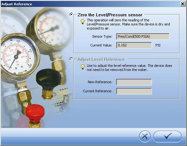
Copyright © 2008-2012 by In-Situ Inc. All rights reserved.
Revision history       released January 2007
		                     rev. 001 March 2007
		                     rev. 002 September 2007
		                     rev. 003 September 2008
		                     rev. 004 March 2010
		                     rev. 005 March 2011
		                     rev. 006 May 2012
This document contains proprietary information which is protected by copyright. No part of this document
may be photocopied, reproduced, or translated to another language without the prior written consent of
In-Situ Inc.

Mailing & Shipping Address:                    Phone: 970-498-500
In-Situ Inc.			                                Fax:      970-498-1598
221 East Lincoln Avenue		                      Internet: www.in-situ.com
Fort Collins, CO 80524		                       Support Line: 800-446-7488
U.S.A.			                                      (U.S.A. & Canada)
The information in this document is subject to change without notice. In-Situ Inc. has made a reasonable
effort to be sure that the information contained herein is current and accurate as of the date of publication.

In-Situ Inc. makes no warranty of any kind with regard to this material, including, but not limited to, its
fitness for a particular application. In-Situ will not be liable for errors contained herein or for incidental or
consequential damages in connection with the furnishing, performance, or use of this material.

In no event shall In-Situ Inc. be liable for any claim for direct, incidental, or consequential damages arising
out of, or in connection with, the sale, manufacture, delivery, or use of any product.

Images in this manual have been selected for illustration; actual images may vary from those shown.

In-Situ and the In-Situ logo, Baro Merge, BaroTROLL, Hermit, Pocket-Situ, RDO, RuggedCable, RuggedReader,
TROLL and Win-Situ are trademarks or registered trademarks of In-Situ Inc. Microsoft, Windows, Excel,
Internet Explorer, Windows Mobile, Windows Vista, ActiveSync, and Windows Mobile Device Center are
trademarks or registered trademarks of Microsoft Corporation. Pentium is a registered trademark of Intel.
Tefzel and Delrin are registered trademarks of E. I. DuPont de Nemours and Company. Viton is a registered
trademark of DuPont Dow Elastomers. Kellems is a registered trademark of Hubbell Inc. Alconox is a
registered trademark of Alconox Company. Lime-A-Way is a registered trademark of Reckitt Benckiser. Other
brand names and trademarks are property of their respective owners.
Contents
1 INTRODUCTION.......................................................................... 6
   System Description ...........................................................................................................................6
   How to Use This Manual...................................................................................................................6
        Conventions.................................................................................................................................8
   Certification..........................................................................................................................................8
   Unpacking and Inspection..............................................................................................................8
        Serial Number.............................................................................................................................8
   To Our Customers . . ..........................................................................................................................9
        Warranty Provisions................................................................................................................10
   How to Contact Us...........................................................................................................................10
        To Obtain Repair Service (U.S.A.)........................................................................................10
        Guidelines for Cleaning Returned Equipment..............................................................12
2 SYSTEM COMPONENTS............................................................. 14
   Instrument..........................................................................................................................................14
   Cable ....................................................................................................................................................14
   Small Desiccant ................................................................................................................................17
        Communication Cables.........................................................................................................18
   Power Components.........................................................................................................................19
   Installation Accessories..................................................................................................................20
   Control Software...............................................................................................................................21
   Product Specifications–General..................................................................................................22
        Product Specifications–Conductivity Sensor................................................................23
        Product Specifications–Pressure (Aqua TROLL 200 Instrument)............................24

Aqua TROLL Operator’s Manual                                                                                                                        Page 3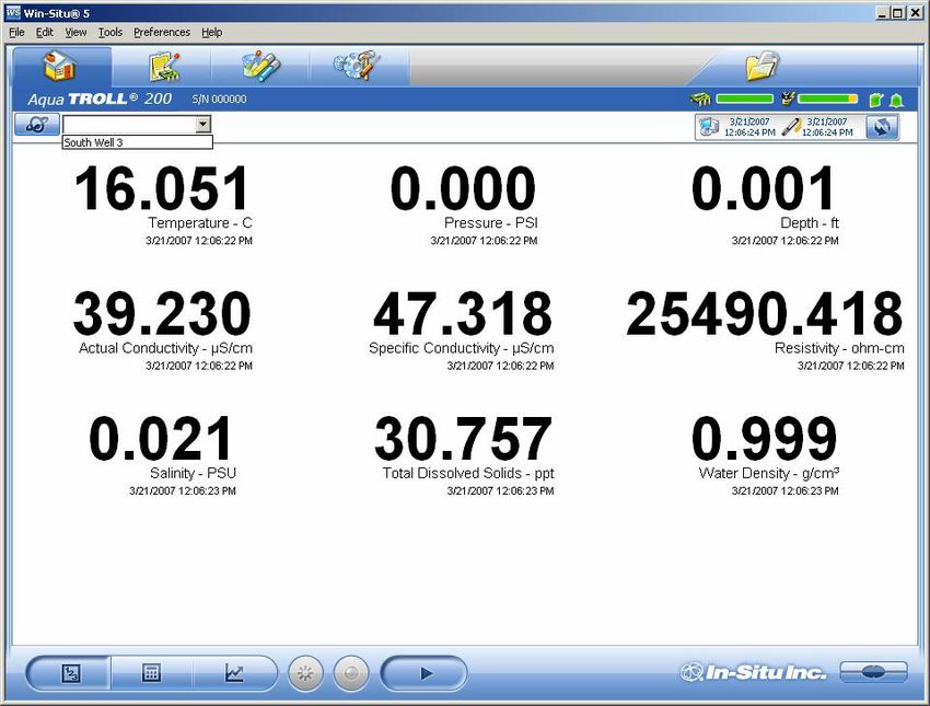
Contents

        Product Specifications–Temperature...............................................................................24
        Product Specifications–Footnotes.....................................................................................25
3 GETTING STARTED.................................................................... 26
   Select a TROLL Com for Communication.................................................................................27
   Install the Software..........................................................................................................................28
        USB TROLL Com Drivers.........................................................................................................28
        Win-Situ Mobile........................................................................................................................28
        Win-Situ Sync.............................................................................................................................28
   Connect the Hardware...................................................................................................................29
        USB TROLL Com........................................................................................................................29
        Twist-Lock Cable Connections............................................................................................30
4 USING WIN-SITU® 5 SOFTWARE................................................. 33
   Launch the Software and Connect Instrument.....................................................................33
   The Home Screen.............................................................................................................................35
        Customizing the Home Screen Display...........................................................................36
   Set the Clock.......................................................................................................................................37
   Add a Site.............................................................................................................................................38
   Check the Conductivity Calibration ..........................................................................................42
   Prepare to Log Data.........................................................................................................................43
        Tips for Aqua TROLL Data Logs...........................................................................................44
   Disconnect..........................................................................................................................................46
5 CONDUCTIVITY......................................................................... 47
   About Conductivity.........................................................................................................................47
        How is Conductivity Measured?.........................................................................................47
   Calibration...........................................................................................................................................48
        Preparing to Calibrate............................................................................................................49
        Calibration Procedure............................................................................................................51
   Available Parameters.......................................................................................................................55

Aqua TROLL Operator’s Manual                                                                                                                     Page 4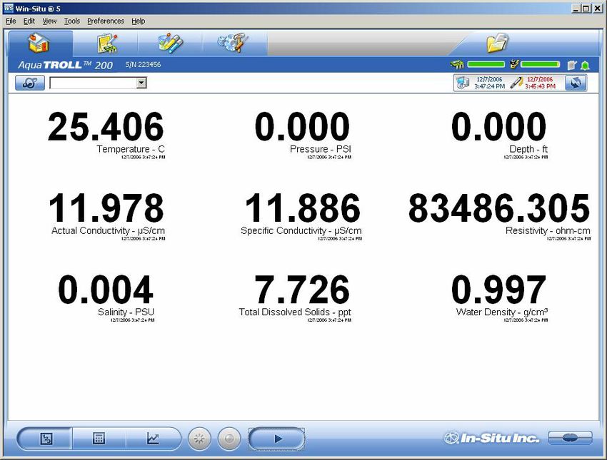
Contents

   Shallow Deployment.......................................................................................................................56
   Maintenance and Recalibration .................................................................................................57
6 PRESSURE AND LEVEL............................................................... 58
   Non-Vented (Absolute) vs. Vented (Gauged) Sensors.........................................................58
   Pressure, Depth, and Level............................................................................................................59
   Configuring Depth and Level.......................................................................................................60
   Pressure Sensor Calibration .........................................................................................................63
   Barometric Compensation of Non-Vented Pressure/Level Data.....................................65
7 FIELD INSTALLATION................................................................ 67
   Positioning the Vented Aqua TROLL 200 Instrument..........................................................67
   Secure the Cable...............................................................................................................................68
   Installation Tips.................................................................................................................................68
   Stabilization Time.............................................................................................................................69
   Shallow Deployment.......................................................................................................................69
   Installation of a Non-Vented Aqua TROLL...............................................................................70
8 ANALOG, SDI-12 AND MODBUS CONNECTIONS............................ 71
   Desiccant.............................................................................................................................................73
   Wiring....................................................................................................................................................73
   Power Connections..........................................................................................................................78
   Communications..............................................................................................................................78
   For More Information......................................................................................................................79
9 CARE & MAINTENANCE............................................................. 80
   Operating Considerations.............................................................................................................80
   Storage.................................................................................................................................................81
   General Maintenance......................................................................................................................81
   Cleaning...............................................................................................................................................82
10 TROUBLESHOOTING................................................................ 84
INDEX........................................................................................ 88
DECLARATIONS OF CONFORMITY................................................... 91

Aqua TROLL Operator’s Manual                                                                                                                        Page 5

1 Introduction

                  System Description
                  The Aqua TROLL® Instrument is a compact, modular system
                  for measuring conductivity and temperature in natural
                  groundwater and surface water, as well as industrial, wastewater,
                  and other installations. Aqua TROLL 200 Instruments have the
                  added capability of measuring level. Components include the
                  instrument, vented and non-vented cables, communication
                  cables, external power accessories, desiccants, and other
                  installation accessories, calibration solutions, and software.

                  How to Use This Manual
                  This Operator’s Manual is designed as a start-up guide and a
                  permanent reference for Aqua TROLL 100 and 200 Instruments.
                  Section 1: Introduction to the Aqua TROLL Operator’s Manual
                  and to In-Situ Inc. — Warranty provisions — Instrument repair &
                  return recommendations
                  Section 2: System Components — Accessories — Product
                  specifications

Aqua TROLL Operator’s Manual                                                 Page 6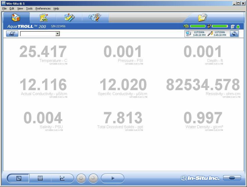
Section 1: Introduction

                    Section 3: Getting Started — Attaching cable — Installing and
                    opening the software
                    Section 4: Using Win-Situ — Connecting for the first time —
                    Customizing the Home screen — Setting the clock — Setting a
                    device site — Calibrating conductivity — Preparing to log data
                    — Disconnecting
                    Section 5: The Conductivity Sensor: Description — Calibration —
                    Available parameters
                    Section 6: The Pressure (Level) Sensor: The two basic types of
                    pressure sensors — Factory and field calibration
                    Section 7: Field Installation — Guidelines and precautions for
                    long-term deployment of the Aqua TROLL Instrument
                    Section 8: Connecting for Use with SDI-12, Analog (4-20 mA), and
                    Modbus Loggers and Controllers
                    Section 9: Care and Maintenance
                    Section 10: Troubleshooting

                               The check mark highlights a tip about a convenient feature of the Aqua TROLL
                               Instrument.

                               The exclamation point calls your attention to a requirement or important
                               action that should not be overlooked.

Aqua TROLL Operator’s Manual                                                                                  Page 7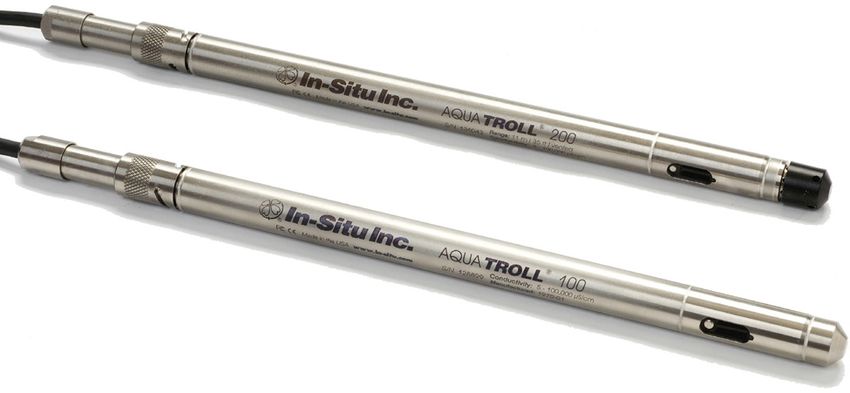
Section 1: Introduction

                                  Conventions
                                  Throughout this operator’s manual you will see the following
                                  symbols.
                                  Certification
                                  The Aqua TROLL Instrument complies with all applicable
                                  directives required by CE and the FCC and found to comply with
                                  EN 61326, ICES-003, and FCC Part 15 specifications. Declarations
                                  of conformity may be found at end of this manual.
                                Unpacking and Inspection
                                Your Aqua TROLL Instrument was carefully inspected before
                                shipping. Check for any physical damage sustained during
                                shipment. Notify In-Situ and file a claim with the carriers involved
            TIP: Please save
                                if there is any such damage; do not attempt to operate the
            packing materials
                                instrument. Accessories may be shipped separately and should
            for future storage
                                also be inspected for physical damage and the fulfillment of your
and shipping of your Aqua TROLL
                                order.
Instrument. The shipping boxes  Serial Number
have been performance-tested
and provide protection for the    The serial number is engraved on the body of the instrument. It
instrument and its accessories.   is also programmed into the instrument and displayed when the
                                  instrument is connected to a computer running Win-Situ® 5 or
                                  Win-Situ® Mobile Software. We recommend that owners keep a
                                  separate record of this number.

Aqua TROLL Operator’s Manual                                                                 Page 8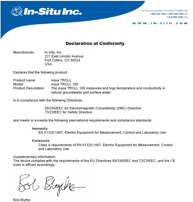
Section 1: Introduction

To Our Customers . . .
Thank you for your purchase of an In-Situ product. We are glad you chose us and our
products to help you with your environmental monitoring needs. In-Situ Inc. has been
designing and manufacturing world-class environmental monitoring instrumentation
for over 25 years in the Rocky Mountains of the United States. As it was in the
beginning, our expectation is that this product will provide you with many trouble-
free years of use. To that end, we pride ourselves on delivering the best customer
service and support possible—24 hours a day, 7 days a week. We believe that this
level of commitment to you, our customer, is imperative in helping you ensure clean,
safe groundwater and surface water resources around the globe. We also understand
the need for accurate, reliable assessments and we continue to make significant
investments in Research and Development to ensure that we deliver the latest product
and technological innovations to support your needs.
Whether you are gathering information about a body of water for a few moments, or
over a period of years, you can rely upon us to provide you with a quality product and
outstanding customer support at a fair price and have that product delivered to you
when and where you need it.
We want your experience with In-Situ Inc. to be pleasant and professional, whether
you are renting or purchasing from us. We would be pleased to hear from you and to
learn more about your needs and your experiences with our products. Again, we thank
you for choosing In-Situ Inc. and we look forward to serving your needs now, and in
the future.

                                      Bob Blythe, President and CEO
                                      In-Situ Inc.
                                      bblythe@in-situ.com
Aqua TROLL Operator’s Manual                                                     Page 9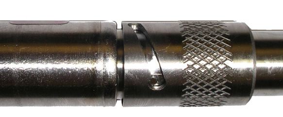
Section 1: Introduction
Warranty Provisions
In-Situ® Inc., (In-Situ) warrants that all new Aqua TROLL® 100
and 200 Instruments shall be free from defects in materials and
workmanship for a period of two years when properly installed and
operated in accordance with the instruction manuals provided by,
or available through, In-Situ Inc., and when used within the design
specifications for the product. Products and accessory products
including batteries, which are manufactured by others, carry the
warranty of that manufacturer, or 30 days, whichever is greater. The
warranty period for all products begins on the day the product is
shipped to the customer or distributor.
The complete Warranty Policy is available on the In-Situ website.
How to Contact Us
Technical Support: 800-446-7488, option 3
Toll-free 24 hours a day in the U.S.A. and Canada
Address: In-Situ Inc.
221 East Lincoln Ave.
Fort Collins, CO 80524 U.S.A.
Phone: 970-498-1500
Fax: 970-498-1598
Internet: www.in-situ.com
e-mail: support@in-situ.com
To Obtain Repair Service (U.S.A.)
If you suspect that your instrument is malfunctioning and repair is
required, you can help ensure efficient servicing by following these
guidelines:
1. Call or e-mail In-Situ Technical Support (support@in-situ.com).
Have the equipment with you when you call.
Aqua TROLL Operator’s Manual Page 10Section 1: Introduction
2. Be prepared to describe the problem, including how the
instrument was used and the conditions noted at the time of
the malfunction.
3. If Tech Support determines that service is needed, they will
ask that you download and complete a Return Materials
Authorization Form available on the In-Situ website under
Contact/Returns for Service.
4. Clean the instrument and cable. Decontaminate thoroughly if
it has been used in a toxic or hazardous environment. See the
Cleaning Guidelines and form on page 13.
TIP: Please keep
5. Remove all sensors and accessories that are not required for
your RMA number
the repair prior to returning unit.
for future reference.
6. Mark the RMA number clearly on the side of the box with a
marker or label.
Please keep your RMA number for future reference. Return unit for
repair to the following address:
In-Situ Inc.
Attn: RMA #XXXXX
221 E. Lincoln Ave.
Fort Collins, CO 80524
U.S.A.
To reduce waste, please use your original shipping container, if it is
in good condition.
The warranty does not cover damage during transit. We recom
mend the customer insure all shipments. Warranty repairs will be
shipped back prepaid.
Aqua TROLL Operator’s Manual Page 11Section 1: Introduction
Outside the U.S.A.
Contact your international In-Situ distributor for repair and service
information.
Guidelines for Cleaning Returned Equipment
If an instrument
returned for Please help us protect the health and safety of our employees by
servicing shows cleaning and decontaminating equipment that has been subjected
evidence of having been to any potential biological or health hazards, and labeling such
deployed in a toxic or hazardous equipment. Unfortunately, we cannot service your equipment
environment, Customer Service without such notification. Please complete and sign the form on
personnel will require written page 13 (or a similar statement certifying that the equipment has
proof of decontamination before been cleaned and decontaminated) and send it along to us with
they can service the unit. each downhole instrument.
• We recommend a cleaning solution, such as Alconox®, a
glassware cleaning product available from In-Situ (Catalog No.
0029810) and laboratory supply houses.
• DO NOT remove the nose cone. DO NOT use any object to
clean the sensor face.
• Clean the pressure sensor by soaking only in cleaning solution
or clean water.
• Clean all cabling. Remove all foreign matter.
• Clean cable connector(s) with a clean, dry cloth. Do not
submerge.
• Clean the probe body—including the nose cone, cable head,
and protective caps. Remove all foreign matter.
Aqua TROLL Operator’s Manual Page 12Section 1: Introduction
If an instrument is returned to our Service Center for repair or recalibration without
a statement that it has been cleaned and decontaminated, or in the opinion of our
Service Representatives presents a potential health or biological hazard, we reserve the
right to withhold service until proper certification has been obtained.
Decontamination & Cleaning Statement
Company Name_______________________________________Phone_____________________
Address________________________________________________________________________
City________________________________ State________________ Zip____________________
Instrument Type_______________________________Serial Number_______________________
Contaminant(s) (if known)_________________________________________________________
______________________________________________________________________________
Decontamination procedure(s) used________________________________________________
______________________________________________________________________________
Cleaning verified by___________________________________ Title_______________________
Date ______________________________
Aqua TROLL Operator’s Manual Page 132 System Components
Instrument
The completely sealed Aqua TROLL Instrument contains
conductivity and temperature sensors, real-time clock,
There are no user- microprocessor, sealed lithium battery, data logger, and memory.
serviceable parts Aqua TROLL 200 Instruments include a vented or non-vented
in the Aqua TROLL pressure sensor in a variety of ranges.
Instrument.
Cable
Several basic cable types are used in the Aqua TROLL system.
• RuggedCable® System, TPU-jacketed (Thermoplastic
Polyurethane),
TIP: Cable vented or non-vented
marking VF =
• Vented Tefzel®-jacketed cable (ETFE fluoropolymer)
vent-free
• Poly-coated stainless steel suspension wire for deployment of
a non-vented instrument
• Communication cables for programming the device/
downloading the logged data
Aqua TROLL Operator’s Manual Page 14Section 2: System Components
RuggedCable® System
Cable includes conductors for power and communication
signals, a weight-bearing structure, and a Kellems® grip
to anchor the Aqua TROLL Instrument securely. Cable is
available in standard and custom lengths.
Uphole and downhole ends are identical female
twist-lock connectors that connect to the Aqua TROLL
Instrument, cable connect TROLL® Com devices,
desiccants, and other accessories.
Vented cable must be used with vented pressure/level
sensors on the Aqua TROLL 200 to achieve gauged
measuresments. The cable vent tube ensures that
atmospheric pressure is the reference pressure applied to
the sensor diaphragm.
Vented cable ships with a small desiccant cap that
should be replaced with a larger volume desiccant
before you deploy the instrument in a humid
environment.
Non-vented cable may be used with non-vented
pressure/level sensors on the Aqua TROLL 100 or 200
Instruments to achieve absolute measurements. Vented
cable can also be used.
Aqua TROLL Operator’s Manual Page 15Section 2: System Components
RuggedCable Stripped-And-Tinned to PLC or
logger
In place of the uphole twist-lock connector, this cable
ends in bare conductors for wiring to a logger or
controller using SDI-12, analog (4-20 mA), or Modbus
communication protocols. Vented cable includes an
outboard desiccant to protect against condensation.
to PLC or logger
Also available in a shorter length ending in
a male twist-lock connector to mate with
RuggedCable.
For connections, refer to wiring diagrams in
Section 8.
to RuggedCable
to Aqua
TROLL
Suspension Wire
Poly-coated stainless steel suspension cable
is ideal for deployment of instruments with
non-vented pressure sensors.
to Aqua
TROLL
Aqua TROLL Operator’s Manual Page 16Section 2: System Components
Small Desiccant
Vented cable includes a clear cap of indicating silica
desiccant to protect the cable and electronics from
condensation during shipping. In humid environments,
replace the small desiccant with a larger-volume
desiccant before deploying the instrument.
Large Desiccant
The optional high-volume desiccant pack attaches to
vented cable and is available with a titanium or plastic
twist-lock connector. Refill kits are available from In-Situ
Inc. or your distributor.
TIP: Protect new
desiccant from
moisture until ready
to use. Outboard Desiccant
Vented stripped-and-tinned cable includes an
outboard desiccant pack attached to the cable vent
tube, and is the same size as the large desiccant.
Replacements and refills are available.
Accessory
Catalog No.
Small desiccant (3)............................................................................................0052230
Large desiccant, ABS connector................................................................0053550
Large desiccant, titanium connector......................................................0051810
Outboard desiccant (replacement).........................................................0051380
Refill kit for large & outboard desiccant................................................0029140
Aqua TROLL Operator’s Manual Page 17Section 2: System Components
Communication Cables
TROLL Com devices enable an instrument to communicate with
a desktop/laptop PC or handheld PDA for profiling, calibrating,
programming, and downloading. TROLL Com devices include
0.9 m (3 ft) vented polyurethane cable,
external power input jack, and a vent External
with replaceable membrane. power input
Vent
TROLL Com (Cable Connect)
Connects a RuggedCable to a serial
or USB port. It is weatherproof and
withstands a temporary immersion RS232
or USB Twist-lock
(IP67). connector
The computer connector
connectors are not TROLL Com (Direct Connect)
submersible. Connects an Aqua TROLL
Instrument directly to a serial or
USB port. It is a good choice for
permanent connection to a PC, or
for programming a non-vented
Aqua TROLL Instrument that will be
deployed without RuggedCable. It is
not submersible or designed for harsh
field conditions.
Accessory Catalog No.
RS232 TROLL Com, Cable Connect..........................................................0056140
USB TROLL Com, Cable Connect...............................................................0052500
RS232 TROLL Com, Direct Connect.........................................................0056150
USB TROLL Com, Direct Connect..............................................................0052510
Aqua TROLL Operator’s Manual Page 18Section 2: System Components
Power Components
Internal Power
TIP: Win-Situ The Aqua TROLL Instrument operates on 3.6 VDC, supplied by a
5 can display sealed, non-replaceable AA lithium battery. Battery life depends
the approximate on sampling speed. The battery typically lasts for 5 years or
percentage of internal battery 200,000 readings, whichever occurs first. One reading is defined
life remaining when the Aqua as date, time, and all available parameters polled or
TROLL Instrument is connected logged from the device.
to a computer.
External Power
External Battery Pack
The sealed, submersible TROLL Battery Pack (lithium)
supplies 14.4 V. When this power source is connected,
TIP: When an Aqua
the Aqua TROLL Instrument will use the external battery
TROLL Instrument is
source first and switch to the internal batteries when
used as an Analog
external battery power is depleted. Typical external
(4-20 mA), SDI-12, or Modbus
battery life when logging all available parameters at
device, power is supplied by
2-minute intervals is approximately 2 years.
the data logger or controller
to which the Aqua TROLL AC Adapter
Instrument is wired.
In-Situ’s AC adapter provides 24 VDC, 0.75 A, AC input 100-
250 V, includes North American power cord. The Programming
Use only In-Situ’s AC Cable includes an external power input for connection to this
adapter. Damage adapter.
to the Aqua TROLL
Instrument caused by the use
of third-party converters is not Accessory Catalog No.
covered by the warranty. External Battery Pack.......................................................................................0051450
AC Adapter 24V..................................................................................................0052440
Aqua TROLL Operator’s Manual Page 19Section 2: System Components
Installation Accessories
• Twist-Lock Hanger: titanium hanger to seal and suspend a
non-vented Aqua TROLL Instrument while taking data; no
venting, no communication capabilities
• Cable Extender: connects two lengths of RuggedCable
Twist-lock Hanger
• Wellcaps, locking and vented
• Well Docks: top-of-well support for 2”, 4”, or 6” well
• Panel-mounted bulkhead for connection to RuggedCable
Accessory Catalog
Cable Extender No.
Twist-lock Hanger, titanium...........................................................0051480
Cable Extender...................................................................................0051490
Locking Wellcap, 2” ..........................................................................0020360
Locking Wellcap, 2” vented ...........................................................0020370
Locking Wellcap
Locking Wellcap, 4” ..........................................................................0020380
Locking Wellcap, 4” vented ...........................................................0020390
Top-of-well installation ring.......................................WELL DOCK 2”, 4”, 6”
Bulkhead connector.........................................................................0053240
Well Dock
Bulkhead Connector
Aqua TROLL Operator’s Manual Page 20Section 2: System Components
Control Software
Win-Situ® 5 Software is easy-to-use software for programming
Aqua TROLL Instruments.
Win-Situ provides instrument control for direct reads and
profiling, calibration, long-term data logging, data downloads,
data viewing, data export to popular spreadsheet programs,
choice of units and other display options, and battery/memory
usage tracking. Win-Situ® Plus enables configuration of networks
and telemetry.
Minimum system requirements: 400 MHz Pentium® II processor;
128 MB RAM, 100 MB free disk space; Internet Explorer® 6.01
or higher; Windows® 2000 Professional SP4 or higher, Windows
XP Professional SP2 or higher, or Windows Vista SP1 or higher;
Windows 7 or higher, CD-ROM drive; serial or USB port.
Win-Situ® Mobile Software provides the features and functions
of Win-Situ 5 on a field-portable platform. Requirements: In-
Situ RuggedReader® Handheld PC with Microsoft Windows
Mobile® operating system (RuggedReader, Windows Mobile 5
or later), serial communications port, and at least 16 MB for data
storage (SD card, CF card, or the device’s built-in non-volatile
memory). For installation and file exchange, Windows® 7 requires
Windows® Mobile Device Center to be installed on the computer.
Earlier versions of Windows require Microsoft® ActiveSync®.
Accessory Catalog No.
Win-Situ 5 (no license required).................................................................0051980
Win-Situ 5 Plus license....................................................................................0053560
Win-Situ Mobile license for RuggedReader.............................0047520
Win-Situ Mobile license (upgrade from Pocket-Situ 4)........0047550
Aqua TROLL Operator’s Manual Page 21Section 2: System Components Product Specifications–General Aqua TROLL Operator’s Manual Page 22
Section 2: System Components

Product Specifications–Conductivity Sensor

Aqua TROLL Operator’s Manual                 Page 23
Section 2: System Components

Product Specifications–Pressure (Aqua TROLL 200 Instrument)

Product Specifications–Temperature

Aqua TROLL Operator’s Manual                             Page 24
Section 2: System Components

Product Specifications–Footnotes

Aqua TROLL Operator’s Manual       Page 25
3 Getting Started
                  This section provides a quick overview of the initial steps
                  necessary to get the instrument ready to communicate:

                  4 Select the appropriate TROLL Com for communication. This
                     determines the hardware connections, and may influence
                     the software installation. The drawing on the following page
                     shows the function of the different TROLL Com models.
                  4 Install the software.
                  4 Connect the hardware, based on the selected TROLL Com.
                  4 Open the software and establish communication with the
                     Aqua TROLL Insturment. See Section 4 of this manual for an
                     overview of Win-Situ operations.

Aqua TROLL Operator’s Manual                                                    Page 26
Section 3: Getting Started
Select a TROLL Com for Communication
The figure below shows the function and connectability of the
different models of TROLL Com.
Serial port USB port
TIPS: A Direct
Connect TROLL Com
RS232 USB
may be preferred for connections connections
programming an Aqua TROLL
Instrument that will be deployed
on wire.
Direct Connect
RuggedCable and a Cable TROLL Coms:
Connect TROLL Com are required Not designed for
for communication with the submersion
device while deployed, but
programming can be done with
any TROLL Com connection.
An RS232 (serial) TROLL
Com is needed for use with a
RuggedReader.
Cable Connect TROLL Coms:
Designed for field use
Aqua TROLL Operator’s Manual Page 27Section 3: Getting Started
Install the Software
Install Win-Situ 5 Software from the In-Situ software/resource CD
or from the In-Situ website:
TIP: If using a USB • Click on Win-Situ 5, and follow the instructions to install Win-
TROLL Com, be sure Situ 5 to your local hard drive.
to select the option
“Install USB TROLL Com Drivers” USB TROLL Com Drivers
when installing Win-Situ 5. • If using a USB TROLL Com, be sure to select the option "Install
USB TROLL Com Drivers." Two drivers will be loaded to your
hard drive, one for the USB TROLL Com, one for the USB
TROLL Com serial port.
Win-Situ Mobile
For communication using a RuggedReader Handheld PC in
the field, install the desktop component of Win-Situ Mobile
on a desktop/laptop PC from the CD or website: The desktop
component is called the Win-Situ Software Manager, and is
TIP: If using
needed to install Win-Situ Mobile on the RuggedReader.
Windows 7, ensure
that Windows 1. Click on Win-Situ Mobile and follow the instructions to install
Mobile Device Center is installed. the Win-Situ Software Manager to your local hard drive.
If using an operating system
2. Connect the RuggedReader to the desktop computer,
prior to Windows 7, ensure that
establish a connection in Microsoft ActiveSync®, launch the
Microsoft ActiveSync is installed
Win-Situ Software Manager, and follow the instructions to
on the desktop or laptop PC and a
install Win-Situ Mobile on the RuggedReader.
Guest connection or partnership
has been established between the Win-Situ Sync
computers.
If you plan to synchronize log files from the RuggedReader to a
PC after collecting data in the field, install Win-Situ Sync from the
CD or website.
Aqua TROLL Operator’s Manual Page 28Section 3: Getting Started
Connect the Hardware
1. Connect the Aqua TROLL Instrument to the selected TROLL
Com as illustrated earlier in this section.
• Direct Connect: Attach via push-on connection to the
Aqua TROLL back end.
• Cable Connect: Connect the twist-lock connectors on the
Aqua TROLL Instrument and the RuggedCable.
2. Insert the TROLL Com into the computer port.
USB TROLL Com
When you plug in a USB TROLL Com, the USB drivers that were
downloaded when you installed Win-Situ 5 will be installed.
• After installation, check as follows to find which COM port the
connected USB TROLL Com is using:
• Windows 2000, Windows XP: Control Panel > System >
Hardware tab > Device Manager > Ports. Click the plus sign to
display the ports.
• Windows Vista and 7: Control Panel > System > Device
Manager (Administrator permission required) > Ports. Click
the plus sign to display the ports.
After connections are made, you are ready to launch the
software and program the Aqua TROLL Instrument. Section 4
of this manual is an overview of Win-Situ. For more detailed
information, see the Win-Situ Help menu.
Aqua TROLL Operator’s Manual Page 29Section 3: Getting Started
Twist-Lock Cable Connections
1. Remove the protective caps from the Aqua TROLL connector
end and cable connector end.
TIP: Retain the dust
caps to protect the
pins and O-ring from
damage when cable is Aqua TROLL
(or Cable Connect TROLL Com) Cable
not attached.
2. Look at the connectors. Each has a flat side.
Flat Flat
Aqua TROLL
(or Cable Connect TROLL Com)
Cable
Note the pins on the instrument connector (one on each
side) and the slots on the cable connector (one on each side).
Pin Slot
Aqua TROLL Operator’s Manual Page 30Section 3: Getting Started
3. Slide back the sleeve on the cable connector.
4. Position the flat edges so they will connect properly, and
insert the instrument connector firmly into the cable
connector.
Aqua TROLL Cable
5. Slide the sleeve on the cable toward the Aqua TROLL until the
pin on the probe fits into the round hole in the slot on the
cable connector.
6. Grasp the textured section of the cable connector in one
hand and the Aqua TROLL in the other. Push and twist firmly
so that the pin on the body connector slides along the slot on
the cable connector and locks securely into the other hole.
Aqua TROLL Cable Aqua TROLL Cable
Aqua TROLL Operator’s Manual Page 31Section 3: Getting Started
7. To attach a Cable Connect TROLL Com, first remove the
desiccant from the cable by grasping the textured section
of the cable connector in one hand and the desiccant in the
other. Twist in opposite directions to unlock the desiccant
from the cable.
Make sure you
hear the “click.” The
“click” ensures the
cable is securely attached.
8. Position the flat edges so they will connect properly, and
insert the TROLL Com connector firmly into the cable
connector.
9. Push, twist, and click to lock.
Aqua TROLL Operator’s Manual Page 324 Using Win-Situ® 5 Software
Win-Situ 5 Software is the In-Situ instrument control software for
Aqua TROLL Instruments. Use Win-Situ to:
• Display real-time readings from the connected Aqua
TROLL, in meter, tabular, or graphic format
• Program the device to log data; download the logged data
• Calibrate the conductivity sensor, select output parameters
TIP: Win-Situ
and units
Mobile provides
Win-Situ 5 features • Customize the output of a pressure/level sensor to record
and functionality in a convenient drawdown, surface water elevation, gauge height, stage
field-worthy platform. height, etc.
• Set communication options in the device—Modbus, SDI-
12, analog, IP, telemetry, etc.
Launch the Software and Connect Instrument
1. Start Win-Situ by double-clicking the shortcut created
on the desktop during installation.
Aqua TROLL Operator’s Manual Page 33Section 4: Using Win-Situ
Win-Situ opens and displays the Data area (“Data tab”),
shown below.
2. Check the COM port. The software may ask if you want to
TIP: For direct serial select a COM port. Do one of the following:
connection the port Answer Yes to the prompt, then check or change the port
is usually COM 1. This in the Comm Settings dialog, and click OK to close
is the Win-Situ default. it, or
For USB communication, be sure Answer No to bypass this step.
to select the correct COM port.
3. Win-Situ asks if you want to connect to the device. If the
Aqua TROLL instrument is connected to your computer as
described in the previous section, answer Yes.
TIP: You can turn
off the “Connect C:\Documents and Settings\ [Login] \My Documents\WinSitu Data
now?” prompt:
Select Prefrences menu > General Data tab
Settings, deselect “Prompt for
connect at startup,” click OK. In
this case, connect to the device 2
by clicking the Connect button
.
3
Connect
button
Aqua TROLL Operator’s Manual Page 34Section 4: Using Win-Situ
4. Software connects and displays a reading of all supported
parameters.
Tabs
Dashboard
Home tab
Click here to update readings
in real time Device is connected
Control Panel
The Home Screen
Note the Tabs at the top of the screen—this is the Home tab,
which displays current readings from the connected device.
The Dashboard (status area) shows the device model &
serial number, battery and memory usage, clock, alarms, and
logging status.
The Control Panel contains action buttons. To update the
readings in real time, press .
Note: When this button looks “pressed in” , polling is
active. Before you can perform certain software tasks, you will
need to stop polling by pressing the button again.
Aqua TROLL Operator’s Manual Page 35Section 4: Using Win-Situ
Customizing the Home Screen Display
Changing Units
1. Click the Sensors tab , select the sensor for which you intend
to change units.
2. Click the “Configure” button
TIP: Unit selection
in the control panel.
is not available if the
device is polling or 3. In the Sensor Setup screen, select a
has an active log. parameter, then select a unit. Repeat
for each parameter as necessary.
4. Click OK to return to the
Sensors tab.
Changing the Rate at Which the Readings Update
Also called the “poll rate,” this can range from 1 to 30 seconds.
1. Select Preferences > Home View Settings.
2. Adjust the Poll Rate. Default: 5 seconds.
Changing the Decimal Places Displayed
TIP: All parameters To change the number of decimal places displayed for each
supported by the reading:
device are shown in
the Home screen by default. To 1. Select Preferences > General Settings.
change this, select Preferences > 2. Under Parameter Defaults, select a parameter, then the
Home View Settings. Clear the “significant decimal digits” for each parameter.
check boxes for parameters you Real-Time Graphing
do not want to view. To view a real-time trend graph: click the “Graph” button
To view a graph with a data table below it, select Preferences >
Graph Settings. Check the Data Panel option. Click OK.
Aqua TROLL Operator’s Manual Page 36Section 4: Using Win-Situ
Set specific information in the software. Win-Situ provides many
options. At a minimum:
• Set the Aqua TROLL clock.
TIP: The • Enter a name for the site where the instrument will collect
Preferences option data.
on the Menu • Calibrate the conductivity sensor.
bar allows users to configure • Enter data logging instructions.
instrument software, including: A brief overview is provided here. For more detailed information,
• General settings see the Win-Situ Help menu.
• Comm settings
• Working directory Set the Clock
• Graph settings Data collection schedules depend on the device’s real-time clock.
• Home view settings
• Data view settings Both the device clock and the system (PC) clock are shown on
the dashboard. The clocks update every 2 seconds. If the device
clock differs by more than 2 seconds from the system clock, the
device clock is displayed in red. To synchronize the clocks, click
the “Sync” button .
Clock Sync
button
Device clock
PC clock
Aqua TROLL Operator’s Manual Page 37Section 4: Using Win-Situ
Add a Site
Logged data are organized and filed by the site where the
data were logged. This feature can help you manage data from
TIP: A default site multiple sites. You can create as many sites as you like, with or
is supplied and may without an Aqua TROLL connected. Sites are stored in the site
be used, but it does database in your Win-Situ working directory and are available to
not contain any specific select for any Aqua TROLL, any log.
information on the location data
collection site. For more You will need a site when setting up a data log. Here are the
information on sites, see steps to set up a new site:
Win-Situ Help menu.
1. On the Data tab, click the Site Data folder.
2. Select File menu > New > Site.
TIP: You can also
create a Site Group to
organize multiple sites C:\Documents and Settings\ [Login] \My Documents\WinSitu Data\Site Data
within a Site Group folder. Site Data folder
Data tab
Aqua TROLL Operator’s Manual Page 38Section 4: Using Win-Situ
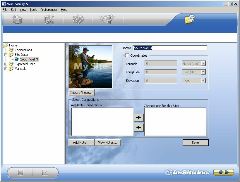
3. In the Site Information screen, enter a name for the site. A
short, descriptive name is best—for example, a project, well,
water body, gauging station, town, nearby landmark, etc.
Length is limited to 32 characters.
TIP: Site A site name is the only required field, but there are many
coordinates are additional options for identifying a site. To include site
optional. They are Coordinates, check Coordinates, then enter Latitude (0.00
also used to establish the probe to 90.00, select North or South from listbox), Longitude (0.00
location for dynamic specific to 180.00, select East or West) and Elevation (select Feet or
gravity calculation, if used. See Meters). You can add a short descriptive Note, import a site
the Win-Situ Help menu, or Photo (bitmap), and/or specify a custom Connection. (If any
Section 6 below. connections have been defined, they will be displayed.)
4. When finished, click Save to save the site.
Name the site
Save the site
Aqua TROLL Operator’s Manual Page 39Section 4: Using Win-Situ
The new site will appear in the Site Data folder, and Win-Situ
will add it to the site database in the working directory on
your computer. It is now available to select for any device,
any log.
New site
appears in Site
Data folder
Aqua TROLL Operator’s Manual Page 40Section 4: Using Win-Situ
5. To set this new site in the connected Aqua TROLL Instrument:
Return to the Home tab, click the down arrow beside the site
box, and select your new site.
This site now becomes the “current” site for the connected
Aqua TROLL Instrument, and is available to use in data logs.
Select the site
Aqua TROLL Operator’s Manual Page 41Section 4: Using Win-Situ
Check the Conductivity Calibration
The conductivity sensor in the Aqua TROLL has been calibrated
during manufacturing to produce a linear response across
the operating range.
We recommend you check the specific conductivity
reading in the solution shipped with your instrument. If
the device is reading accurately, there is no need to field-
calibrate the instrument unless SOPs require it.
To perform a field calibration you will need:
For best results we
recommend you The In-Situ Cal Cup, or other suitable container that
read and f ollow allows for complete immersion of the conductivity
the conductivity calibration sensor, including the temperature “button,” which
procedure in Section 5 of this can be seen on one side of the probe. The Cal Cup is
Operator’s Manual. recommended for the first calibration.
Temperature
The calibration standard solution
supplied, or other solution of known Conductivity
specific conductivity in the range 100 to Pressure
60,000 µS/cm.
The complete calibration procedure takes
only a few minutes and may be done in a
field or office/lab setting with a software connection in Win-Situ
5 or Win-Situ Mobile Software. A detailed description of the
conductivity calibration procedure, including:
• Preparation of the Aqua TROLL
• Software input
• Calculated output
• Hints for successful calibration
is in Section 5 of this manual.
Aqua TROLL Operator’s Manual Page 42Section 4: Using Win-Situ
Prepare to Log Data
1. To program the device to log data, go to the Logging tab.
2. Click the “New” button.
TIP: Stop “polling”
in the Home screen
before setting up a
data log.
Logging tab
“New” button
TIP: For more
complete information
on setting up
data logs, see the The Logging Setup Wizard will guide you through the
Win-Situ Help menu. configuration of a data log—including the site, log name,
parameters to measure, sample schedule, start time, stop time,
level output, and other options.
Aqua TROLL Operator’s Manual Page 43Section 4: Using Win-Situ
Tips for Aqua TROLL Data Logs
• Nine parameters are available for the Aqua TROLL 200
Instrument. Seven parameters are available for the Aqua
TROLL 100 Instrument. All selected parameters are logged,
with implications for battery and memory usage.
• Only one active log can reside in the device at a time.
An active log is a log that is Ready, Pending, Running, or
Suspended as shown in the Status column of the Logging
Tab.
• To avoid draining the Aqua TROLL battery prematurely,
external power is required for Event logging, and
recommended for Linear Average logging.
• For information on selecting a Level output, refer to the Win-
Situ Help menu, or Section 6 in this manual.
• For a non-vented Aqua TROLL that will be deployed on wire,
be sure to select a Scheduled Start so the log will start by
itself, without a communication connection.
• For more complete information on setting up data logs, see
the Win-Situ Help menu .
Aqua TROLL Operator’s Manual Page 44Section 4: Using Win-Situ
TIP: As an To Start logging:
alternative to the
log control buttons, • A “Pending” (scheduled) log will start at its programmed time.
right-click a log • You can start a “Ready” (manual) log at any time
to display a short while connected by selecting the log and pressing “Start” .
context menu of To Stop logging:
available actions. • Select the log and press the “Stop” button .
• Or suspend (temporarily stop) it with the “Pause” button .
TIP: The available
log control buttons
To Download the log to the connected PC:
will vary depending • Select the log and press the “Download” button .
on the status of the To View the log after downloading:
selected log.
• Go to the Data tab and select the log; for a graph press .
“Start” button
“Ready” log
Logging tab
Log control buttons
Aqua TROLL Operator’s Manual Page 45Section 4: Using Win-Situ
Disconnect
After the Aqua TROLL is programmed to log data, you are ready to:
• Exit the software (File menu > Exit).
Remove the dust
• Disconnect the TROLL Com from the cable connector, by
cap from the
grasping the textured section of the cable connector in one
desiccant before
hand and the TROLL Com in the other. Twist in opposite
deployment to allow air to reach
directions to unlock the TROLL Com from the cable.
the cable vent tube.
• Vented cable: Attach desiccant to the cable connector—line
up the flat sides of the connectors, push, twist, and click to
lock the desiccant to the cable. Remove red dust cap from the
desiccant’s vent.
• Non-vented Aqua TROLL (or installations where vented
pressure or communication are not required): Attach a non-
vented cable or twist-lock hanger and suspension wire.
• Install the instrument in its field location. See Section 7 for
guidelines.
Aqua TROLL Operator’s Manual Page 465 Conductivity
About Conductivity
Conductivity measures the ability of a material to carry an
electric current. Generally, the higher the concentration of
dissolved salts and minerals in water, the better the water is
as a conductor, therefore the electrical conductivity is higher.
Deionized/distilled water is a poor conductor because almost
all anions and cations are removed during the deionization/
distillation process.
If conductivity changes in a body of water, it often indicates an
environmental event. For example, a dramatic increase in the
electrical conductivity of an underground fresh water aquifer
located near the ocean could indicate the beginning of saltwater
intrusion. On the other hand, an increase in the electrical
conductivity of a small lake that is completely surrounded
by farmland may simply be the result of runoff from recent
precipitation.
How is Conductivity Measured?
Conductance is the reciprocal of the resistance, in ohms,
measured between two opposing electrodes of a 1 cm cube at
a specific temperature. The unit 1/ohm or mho was given the
name of Siemens (S) for conductance. It is not practical to require
all conductance cells to have the dimensions of an exact cube. To
Aqua TROLL Operator’s Manual Page 47Section 5: Conductivity
enable the comparison of data from experiments with different
conductance cells, the conductance is multiplied by the cell
constant to show conductivity in Siemens per centimeter (S/cm).
Cell constants are determined for each sensor using a standard
solution of known conductivity. The cell constant depends on
the electrode area and the amount of separation or distance
between the electrodes.
The four-electrode conductivity cell contains two drive
electrodes and two sensing electrodes. In the Aqua TROLL
instrument, each drive electrode is composed of two
interconnected pins, for a total of six pins. The sensing electrodes
are positioned in a low current area to minimize electrode
fouling. An alternating current is used to drive the cell. This
reduces errors caused by polarization resulting from the
application of a direct current.
Calibration
The conductivity sensor in the Aqua TROLL instrument has been
calibrated during manufacturing to produce a linear response
across the operating range. Standard Operating Procedures
for measuring conductivity in the field typically specify that
the sensor shall be calibrated before use, close to the expected
temperature and conductivity conditions. The accuracy of
the sensor depends on the calibration solution used and the
TIP: When operator’s technique.
calibrating below We recommend that you check the specific conductivity reading
1,000 µS/cm, in the solution shipped with your instrument. If the device
additional care must be taken is reading accurately, there is no need to field-calibrate the
to prevent the calibration instrument unless SOPs require it.
solution from drifting due to
atmospheric exposure. The Aqua TROLL instrument can be calibrated at any point in the
operating range. However, best results will be obtained in the
Aqua TROLL Operator’s Manual Page 48You can also read