BWH 001 WLAN HGW Base Station - Technical Manual - Sigmatek
←
→
Page content transcription
If your browser does not render page correctly, please read the page content below
BWH 001
           WLAN HGW Base Station

                               Technical Manual

Date of creation: 06.08.2018     Version date: 05.03.2020   Article number: 12-246-001-E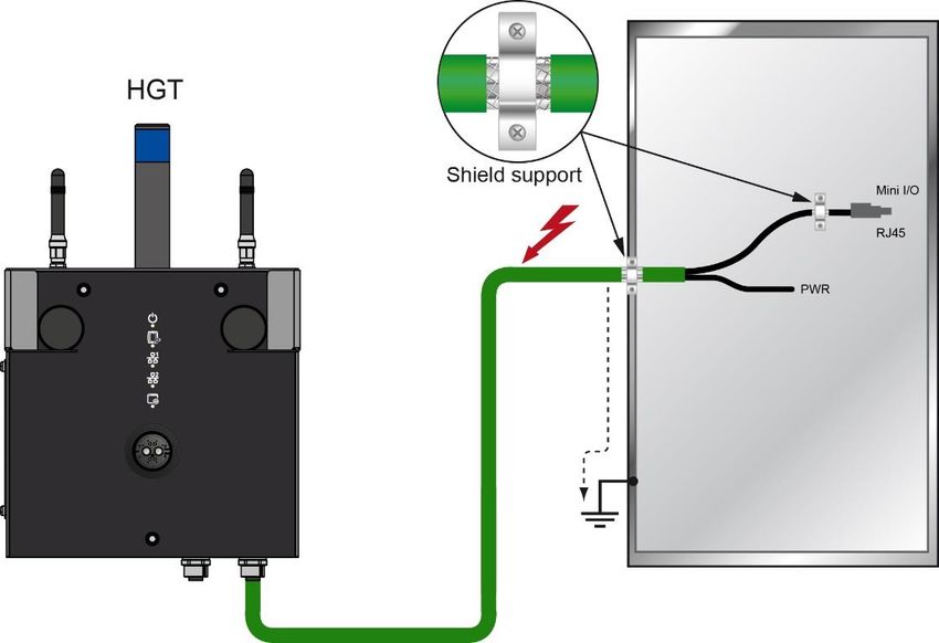
Publisher: SIGMATEK GmbH & Co KG
                                   A-5112 Lamprechtshausen
                                      Tel.: +43/6274/4321
                                    Fax: +43/6274/4321-18
                                   Email: office@sigmatek.at
                               WWW.SIGMATEK-AUTOMATION.COM

                                               Copyright © 2018
                                            SIGMATEK GmbH & Co KG

                                      Translation from German

All rights reserved. No part of this work may be reproduced, edited using an electronic system, duplicated or dis-
tributed in any form (print, photocopy, microfilm or in any other process) without the express permission.

We reserve the right to make changes in the content without notice. SIGMATEK GmbH & Co KG is not responsible for
technical or printing errors in the handbook and assumes no responsibility for damages that occur through use of
this handbook.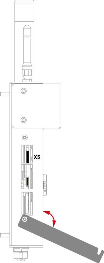
WLAN HGW BASE STATION                    BWH 001

Base Station                                                                BWH 001
The BWH 001 base station acts as a gateway and establishes a connection between an HGW
and a machine control. Depending on the S-DIAS controller used (e.g. CP/SCP 111), both
safety data (via black channel) and non-safety data can be transmitted redundantly. In addi-
tion, the BWH 001 serves as a receiving and charging station for the HGW.

The signal lamp allows a simple coupling between HGW and machine. States can be made
visible via programmable pictogram LEDs. The base station can also communicate with other
controllers over an Ethernet interface.

05.03.2020                                                                          Page 1
BWH 001           WLAN HGW BASE STATION

Contents
1    Introduction ............................................................................. 6
     1.1          Target Group/Purpose of this Manual ........................................ 6

     1.2          Important Reference Documentation ......................................... 6

     1.3          Contents of Delivery ..................................................................... 6

2    Basic Safety Guidelines ......................................................... 7
     2.1          Symbols Used ............................................................................... 7

     2.2          Disclaimer ...................................................................................... 8

     2.3          General Safety Guidelines ........................................................... 9

     2.4          Designated Use ........................................................................... 10

     2.5          Software/Training ....................................................................... 12

3    Residual Risks .......................................................................13
     3.1          Safety of the Machine or Equipment ........................................ 13

     3.2          Technical Guidelines .................................................................. 14

     3.3          Guidelines.................................................................................... 15
          3.3.1        EU Declaration of Conformity ............................................................ 15

4    Technical Data .......................................................................16
     4.1          Performance Data ....................................................................... 16

     4.2          Electrical Requirements ............................................................. 17

     4.3          Environmental Conditions ......................................................... 17

     4.4          Wireless ....................................................................................... 18
          4.4.1        WLAN 2.4 GHz .................................................................................. 18

Page 2                                                                                                   05.03.2020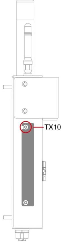
WLAN HGW BASE STATION                                      BWH 001

        4.4.2         WLAN 5 GHz .................................................................................... 18

        4.4.3         Antennae........................................................................................... 18

      4.5        Miscellaneous ............................................................................. 19

5    Mechanical Dimensions ........................................................ 20

6    Interfaces ............................................................................... 21
      6.1        Connections Bottom................................................................... 21
        6.1.1         X1: M12 Y-coded (supply, Ethernet) ................................................. 21

        6.1.2         X2: M12 D-coded (Ethernet) ............................................................. 21

      6.2        Side Connections........................................................................ 22
        6.2.1         X3: USB 2.0 DualRole (Type C)........................................................ 23

        6.2.2         X5: microSD Card ............................................................................. 23

      6.3        Front connectors ........................................................................ 24
        6.3.1         X4 Power/Data .................................................................................. 25

      6.4        Display ......................................................................................... 26
        6.4.1         Front LEDs ........................................................................................ 26

        6.4.2         Signal Light ....................................................................................... 28

      6.5        WLAN ........................................................................................... 29

7    Status and Error Messages .................................................. 31

8    Transport/Storage ................................................................. 39

9    Assembly/Installation ........................................................... 40
      9.1        Conditions ................................................................................... 40

      9.2        Check List .................................................................................... 42

05.03.2020                                                                                                        Page 3
BWH 001 WLAN HGW BASE STATION
9.2.1 Check Contents of Delivery ............................................................... 42
9.2.2 Checking Space Requirement ........................................................... 42
9.2.3 Determining Antennae Positions ....................................................... 42
9.2.4 Mounting the Base Station................................................................. 42
9.2.5 Placing the Installation Number ......................................................... 43
9.3 Mounting Help ............................................................................. 43
9.4 Wiring ........................................................................................... 43
9.4.1 Ground/Shielding ............................................................................... 44
9.4.2 ESD Protection .................................................................................. 44
10 Operation/Start-up .................................................................45
10.1 Standard Configuration .............................................................. 45
10.1.1 Standard Application ......................................................................... 46
10.2 Configuration .............................................................................. 46
10.3 Testing the Operating Area........................................................ 47
10.4 Operation ..................................................................................... 47
10.4.1 Coupling the Operating Panel............................................................ 47
10.4.2 Decoupling the Operating Panel ........................................................ 48
11 Help with Disruptions/Troubleshooting ...............................49
12 Maintenance ...........................................................................50
12.1 Cleaning the Device Surface ..................................................... 50
12.2 Maintenance ................................................................................ 50
12.2.1 Exchanging the microSD Card .......................................................... 51
12.3 Repair ........................................................................................... 53
Page 4 05.03.2020WLAN HGW BASE STATION BWH 001
13 Disposal ................................................................................. 54
14 Accessories ........................................................................... 54
14.1 microSD Card .............................................................................. 54
14.2 Cable ............................................................................................ 54
14.3 Antennae ...................................................................................... 54
14.4 Configuring Safety Components............................................... 54
05.03.2020 Page 5BWH 001 WLAN HGW BASE STATION
1 Introduction
1.1 Target Group/Purpose of this Manual
This manual contains all information required for the safety-related operation of the BWH 001.
This manual is intended for:
• Project planners
• Technicians
• Configurators/commissioning engineers
• Machine operators
• Maintenance/test technicians
General knowledge of automation technology in safety-related systems is required.
Further help and information on training and the appropriate accessories can be found on our
website www.sigmatek-automation.com
Our support team is happily available to answer your questions.
Please see our website for our hotline number and business hours.
1.2 Important Reference Documentation
• Safety System Handbook
• HGW_BWH_Configuration Manual
• WLAN Configuration
• Connection Cables for Operating Devices
These documents can be downloaded from our website or obtained through support.
1.3 Contents of Delivery
1x BWH 001
This document can be downloaded from our website.
Additional documents may be included with delivery.
Page 6 05.03.2020WLAN HGW BASE STATION BWH 001
2 Basic Safety Guidelines
2.1 Symbols Used
The following symbols are used in the operator documentation for warning and danger mes-
sages, as well as informational notes:
DANGER Identifies an immediate danger with high risk, which will lead to immediate
death or serious injury if not avoided.
Identifie un danger immédiat avec un risque élevé, entraînant le décès im-
médiat ou des blessures graves s’il n’est pas évité.
WARNING Identifies a possible danger with a mid-level risk, which can lead to death or
(serious) injury if not avoided.
Indique un danger possible d’un risque moyen de décès ou de (graves) bles-
sures si les consignes de sécurité ne sont pas respectées
CAUTION Identifies a low risk danger, which can lead to injury or property damage if
not avoided.
Indique un danger avec un niveau de risque faible des blessures légères ou
des dommages matériels si les consignes de sécurité ne sont pas respec-
tées.
Warning, dangerous electrical voltage.
Attention, tension électrique dangereuse.
Provides user tips, informs of special features and identifies especially im-
portant information in the text.
Fournit des conseils d’utilisation, informe sur les fonctions particulaires et
souligne les informations particulièrement importantes dans le texte.
Danger for ESD-sensitive components.
Les signes de danger pour les composants sensibles aux décharges élec-
trostatiques.
05.03.2020 Page 7BWH 001 WLAN HGW BASE STATION
2.2 Disclaimer
The contents of this document were prepared with the greatest care. How-
ever, deviations cannot be ruled out. This document is regularly checked and
required corrections are included in the subsequent versions. The machine
manufacturer is responsible for the proper assembly, as well as device con-
figuration. The machine operator is responsible for safe handling, as well as
proper operation.
The current document can be found on our website. If necessary, contact our
support.
Subject to technical changes, which improve the performance of the devices.
The following documentation represents a series of product descriptions. It
does not guarantee properties under the warranty.
Please thoroughly read the corresponding data sheets, operating instructions
and this system manual before handling a product.
SIGMATEK GmbH & Co KG is not liable for damages caused through
non-compliance with these instructions or applicable regulations.
The general and special safety instructions described in the following sec-
tions, as well as technical regulations, must therefore be observed.
Page 8 05.03.2020WLAN HGW BASE STATION BWH 001
2.3 General Safety Guidelines
According to EU Guidelines, the operating instructions are a component of a
product.
This manual must therefore be accessible in the vicinity of the machine since
it contains important instructions.
This technical documentation should be included in the sale, rental or transfer
of the product, or its online availability indicated.
Maintain this manual in readable condition and keep it accessible for refer-
ence.
Regarding the requirements for Safety and health connected to the use of
machines, the manufacturer must perform a risk assessment in accordance
with machine guidelines 2006/42/EG before introducing a machine to the
market.
Before commissioning this product, check that conformance with the provi-
sions of the 2006/42/EG guidelines is correct. As long as the machine, with
which the with the HGW or BWH should be used does not comply with the
guideline, operating this product is prohibited.
Operate the unit with devices and accessories approved by SIGMATEK only.
CAUTION Handle the device with care and do not drop or let fall.
Prevent foreign bodies and fluids from entering the device.
The device must not be opened, otherwise it could be damaged!
Manipulez l’appareil avec précaution et ne le laissez pas tomber.
Empêchez les corps étrangers et les liquides de pénétrer dans l’appareil.
L’appareil ne doit pas être ouvert, sinon il risque d’être endommagé !
Regularly check the housing for mechanical damage.
Vérifier régulièrement l’absence de dommages mécaniques sur le boîtier.
05.03.2020 Page 9BWH 001 WLAN HGW BASE STATION
2.4 Designated Use
The Safety functions implemented in the Safety modules are designed for use with safety-
related applications in a PLC control and meet the required conditions for safe operation in
SIL 3 or SIL CL 3 according to EN 62061 and in compliance with PL e. Cat. 4 in accordance
with EN ISO 13849-1.
CAUTION The instructions contained in this document must be followed.
The BWH 001 can only be powered by supplies that meet the requirements
for SELV or PELV in compliance with EN 60204.
For error-free operation, proper transport and storage are essential. See
chapter 8 for more information.
Installation, mounting, programming, initial start-up, operation, maintenance
and decommissioning can only be performed by qualified personnel.
Qualified personnel in this context are people who have completed training
or have trained under supervision of qualified personnel and have been au-
thorized to operate and maintain safety-related equipment, systems and fa-
cilities in compliance with the strict guidelines and standards of safety tech-
nology. The applicable environmental conditions must be maintained.
Les instructions contenues dans ce document doivent être suivies.
Le BWH 001 ne peut être alimenté que par des alimentations répondant aux
exigences des normes SELV ou PELV selon EN 60204.
Pour un fonctionnement sans erreur, le transport et le stockage appropriés
sont essentiels. Voir le chapitre 8 pour plus d’informations.
L’installation, le montage, la programmation, la mise en service initiale, l’ex-
ploitation, la maintenance et la mise hors service ne peuvent être effectués
que par une personne qualifiée.
Dans ce contexte, on entend par personnel qualifié les personnes qui ont
suivi une formation ou qui ont été formées sous la supervision d’un personnel
qualifié et qui ont été autorisées à utiliser et à entretenir l’équipement, les
systèmes et les installations de sécurité conformément aux directives et aux
normes strictes de la technique de sécurité. Les conditions environnemen-
tales applicables doivent être respectées.
Page 10 05.03.2020WLAN HGW BASE STATION BWH 001
For your own safety and that of others, the safety modules should be used
for their designated purpose only.
Correct EMC installation is also included in the designated use.
Pour votre propre sécurité et celle des autres, les modules de sécurité ne
doivent être utilisés qu’aux fins prévues.
Une installation CEM correcte est également incluse dans l’utilisation prévue.
Non-designated use consists of:
• any changes made to the module or the use of damaged modules.
• use of the module inconsistent with the technical margins described
in this manual or the speciation’s defined in the technical data (see
chapter 4).
L’utilisation non désignée consiste en :
• toute modification apportée au module ou l’utilisation de modules
endommagés.
• utilisation du module non conforme aux marges techniques décrites
dans ce manuel ou aux spécifications définies dans les données
techniques (voir chapitre 4).
05.03.2020 Page 11BWH 001 WLAN HGW BASE STATION
CAUTION In addition, the Safety Guidelines in the other sections of these instructions
must be observed. These instructions are visually emphasized by symbols.
The module complies with EN 61131-2.
In combination with a machine, the machine builder must comply with EN
60204-1 standards.
For your own safety and that of others, compliance with the environmental
conditions is essential.
The control cabinet must be connected to ground correctly.
To perform maintenance or repairs, disconnect the system from the power
supply.
En outre, les consignes de sécurité mentionnées dans d’autres sections de
ce manuel doivent être respectées. Ces directives sont indiquées avec les
symboles graphiques.
Le module est conforme à la norme EN 61131-2.
En combinaison avec une machine, le constructeur de la machine doit res-
pecter la norme EN 60204-1.
L’armoire de commande doit être raccordée correctement à la terre.
Pour l'entretien et les réparations, débranchez le système de l'alimentation.
2.5 Software/Training
The application is created with the software LASAL Class 2 and LASAL Screen Editor; the
Safety application is created using the Safety Designer. Basic information on safety can be
found in the Safety System Handbook.
Training for the LASAL development environment is provided, with which you can configure
the BWH. Information on our training schedule is available on our website.
Page 12 05.03.2020WLAN HGW BASE STATION BWH 001
3 Residual Risks
CAUTION According to the EU guideline 2006/42/EG (machine guideline), the machine
manufacturer must perform a risk assessment, which includes the possible
residual risks posed by the product. These include:
• unwanted movements of driven machine components
• unwanted temperatures, emissions of gas, particles, smell and light.
• dangerous contact voltages
• the effects of electrical, magnetic and electromagnetic fields pro-
duced during operation (for example, on pacemakers and implants)
• possible effects of information technology devices (cell/smart
phones etc.)
• release of non-environmentally compatible substances and emis-
sions
Conformément à la directive européenne 2006/42/CE (directive machines),
le fabricant de la machine doit procéder à une évaluation des risques, y com-
pris les risques résiduels éventuels présentés par le produit. Il s'agit notam-
ment de :
• Mouvements involontaires des pièces entraînées de la machine.
• Températures non désirées, les émissions de gaz, les particules,
l'odeur et la lumière.
• Tensions de contact dangereuses
• Les effets des champs électriques, magnétiques et électromagné-
tiques produites pendant le fonctionnement (par exemple, sur les
stimulateurs cardiaques et les implants).
• Les effets possibles sur les dispositifs de technologie de l'informa-
tion (téléphones cellulaires / téléphones intelligents, etc.)
• Dégagement de substances et d'émissions non respectueuses de
l'environnement.
3.1 Safety of the Machine or Equipment
Strict compliance with the safety guidelines is required, otherwise all warranties and claims
are invalid:
Observe all on-site rules and regulations for accident prevention and occu-
pational safety.
05.03.2020 Page 13BWH 001 WLAN HGW BASE STATION
3.2 Technical Guidelines
WARNING The HGW and BWH form a communications unit, which must be configured
by trained personnel. Among other things, careful allocation of the wireless
channels must be ensured. Complete, seamless availability must be guaran-
teed over the entire area of operation to ensure that no dead spots exist at
any location in the area of operation.
Le HGW et le BWH constituent une unité de communication qui doit être
configurée par un personnel qualifié. Entre autres, il faut s'assurer que l'attri-
bution des canaux sans fil est faite avec soin. Une disponibilité complète et
sans faille doit être garantie sur l'ensemble de la zone d'exploitation afin de
s'assurer qu'il n'y a pas de zones mortes en tout point de la zone d'exploita-
tion.
The electrical connections cannot be removed while voltage is applied. Be-
fore removing connections, a controlled shutdown of the machine must be
performed and the supply disconnected.
After shutdown or disconnection of the voltage supply, a wait-time of 5
minutes is required before voltage conducting components can be touched
or connectors removed.
The machine manufacturer is responsible for ensuring the correct handling
of modules and if necessary, for taking organizational measures to secure
access.
Page 14 05.03.2020WLAN HGW BASE STATION BWH 001
3.3 Guidelines
The BWH was constructed in compliance with the following European Union guidelines.
2014/35/EU Low-voltage guideline
2014/30/EU EMC Guideline
2014/53/EU Wireless Device Guideline
2011/65/EU RoHS Guideline
3.3.1 EU Declaration of Conformity
CE Declaration of Conformity
The BWH 001 complies with European norms for programmable logic con-
trols.
• 2014/35/EU Electrical Safety (low voltage guideline)
• 2014/30/EU “Electromagnetic Compatibility” (EMC guideline)
• 2014/53/EU “Directive of the European Parliament and of the Coun-
cil of 16 April 2014 on the harmonization of the laws of the Member
States relating to the provision of wireless equipment on the market
and repealing Directive 1999/5/EC” (wireless device guideline)
• 2011/65/EU Restricted use of certain hazardous substances in
electrical and electronic equipment (RoHS Guideline)
The EU Conformity Declarations are provided on the SIGMATEK website.
05.03.2020 Page 15BWH 001 WLAN HGW BASE STATION
4 Technical Data
4.1 Performance Data
Processor EDGE2 Technology
Processor cores 1
Internal cache 32-kbyte L1 Instruction Cache
32-kbyte L1 Data Cache
512-Kbyte L2 Cache
Internal program and 256-Mbyte
data memory (DDR3 RAM)
Internal remnant no
data memory
Internal storage device 512-Mbyte microSD card, expandable
Internal I/O no
Interfaces 1x magnetic connector for charging the battery
1x M12 connector supply and Ethernet
1x M12 connector Ethernet
1x USB 2.0 Type-C (Dual Role Port)
1x WLAN dual-band (2.4 GHz, 5 GHz simultaneously)
Status LEDs 1x Power
1x HGW-Link (freely programmable)
2x Network (freely programmable)
1x application-/RUN-LED
Signal generator no
Cooling passive (fanless)
Coupling confirmation signal light
Input voltage measurement no
Page 16 05.03.2020WLAN HGW BASE STATION BWH 001
4.2 Electrical Requirements
Supply voltage typically +24 V DC (SELV/PELV)
minimum +20 V DC maximum +30 V DC
Inrush current 16.1 A for 1 ns
Current consumption of +24 V ca. 200 mA in CLI
power supply maximum 2.5 A charging at full capacity at +24 V
USB Host current load maximum 0.5 A
The specified current consumption relates to the status without connected
peripherals (USB stick ...)
4.3 Environmental Conditions
Storage temperature -5 ... +60 °C
Environmental temperature 0 …+50 °C
Humidity 10-95 %, non-condensing
EMC resistance EN 61000-6-2 (industrial area)
EMC noise generation EN 61000-6-4
Shock resistance EN 60068-2-27 150 m/s²
Vibration resistance 10 m/s²
Protection type EN 60529 IP54
Free fall (with packaging) IEC 60068-2-32 1000 mm
05.03.2020 Page 17BWH 001 WLAN HGW BASE STATION
4.4 Wireless
4.4.1 WLAN 2.4 GHz
Frequency range 2399.5-2484.5 MHz
Transmission power max. 20 dBm (100 mW) EIRP
Channels 1-14 (2400-2483.5 MHz)
4.4.2 WLAN 5 GHz
Frequency range 5150-5350 MHz
5470-5725 MHz
Transmission power max. 23 dBm (200 mW) EIRP
Channels 36-64 (5180-5320 MHz)
100-140 (5500-5700 MHz)
4.4.3 Antennae
Number 2
Frequency range 2.4/5 GHz (Dual-Band)
Transmission power max. 25 W
Antennae gain 2.4 GHz-4 dBi Peak Gain
5 GHz-5.2 dBi Peak Gain
Impedance 50 Ω
Transmission angle/ transmission characteristics: omnidirectional
characteristics Polarization: linear
The devices can only be used in the country designated or preconfigured for
this purpose, as the maximum permitted transmission power can greatly
differ.
Non-compliance with these specifications can result in legal consequences,
for which SIGMATEK accepts no liability!
Already during the planning stage, caution must be taken to ensure that the
radio channels are configured so that interference with other products is
prevented.
Page 18 05.03.2020WLAN HGW BASE STATION BWH 001
CAUTION Only antennae approved by SIGMATEK can be used. See chapter 14.3 An-
tennae.
Seules les antennes recommandées par SIGMATEK peuvent être utilisées.
Voir chapitre 13.3 Antennes.
Regularly check the screw fitting for the antennae. If necessary, manually
tighten them or use a torque wrench (1 Nm) for SMA connectors.
Vérifiez régulièrement le vissage des antennes. Si nécessaire, serrez-les ma-
nuellement ou utilisez une clé dynamométrique (1 Nm) pour les connecteurs
SMA.
4.5 Miscellaneous
Article number 12-246-001
Hardware version 1.x
Approvals CE
05.03.2020 Page 19BWH 001 WLAN HGW BASE STATION
5 Mechanical Dimensions
Dimensions 175 x 267.4 x 52.9 mm (W x H x D)
Material housing: steel
color: RAL7024 (powder coated)
front: plexiglass
Weight typically 1.55 kg
Page 20 05.03.2020WLAN HGW BASE STATION BWH 001
6 Interfaces
6.1 Connections Bottom
Appropriate connector cables are available as accessories.
See chapters 14.2 Cable.
6.1.1 X1: M12 Y-coded (supply, Ethernet)
Pin Function
1 Tx+
2 Tx-
3 Rx+
4 Rx-
5 VCC
6 n.c.
7 n.c.
8 GND
n.c. = do not use
6.1.2 X2: M12 D-coded (Ethernet)
Pin Function
1 Tx+
2 Rx+
3 Tx-
4 Rx-
5 n.c.
05.03.2020 Page 21BWH 001 WLAN HGW BASE STATION 6.2 Side Connections Page 22 05.03.2020
WLAN HGW BASE STATION BWH 001
6.2.1 X3: USB 2.0 DualRole (Type C)
Pin Function
A1, B1 GND
A2, B2 n.c.
A3, B3 n.c.
A4, B4 VBUS
A5, B5 CC1, CC2
A6, B6 USB2.0 D+
A7, B7 USB2.0 D-
A8, B8 SBU1, SBU2
A9, B9 VBUS
A10, B10 n.c.
A11, B11 n.c.
A12, B12 GND
The USB Type-C interface serves as the online interface between the device and the pro-
gramming software.
It should be noted that many of the USB devices on the market do not comply
with USB specifications; this can lead to device malfunctions. This can lead
to malfunction of the device. It is also possible that these devices will not be
detected at the USB port or function correctly. It is therefore recommended
that every USB stick or USB supply be tested before actual use.
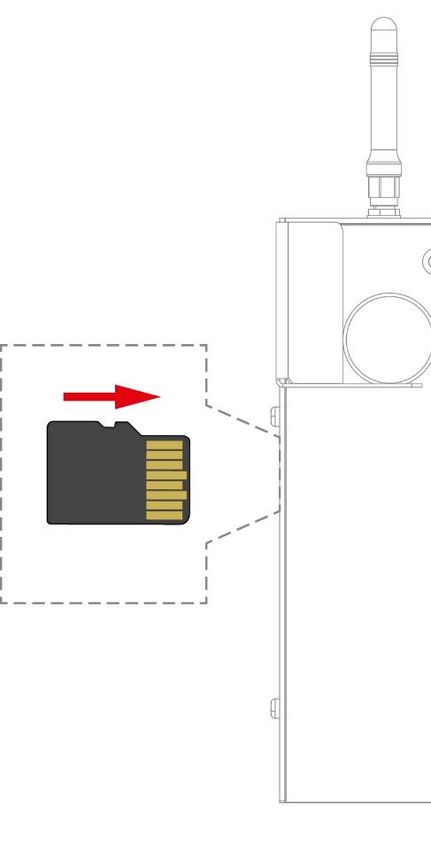
6.2.2 X5: microSD Card
Pin Function
1 DAT2
2 CD/DAT3
3 CMD
4 +3V3
5 CLK
6 GND
7 DAT0
8 DAT1
It is recommended that only storage media provided by SIGMATEK be used.
For the appropriate storage media, see chapter 14.1 microSD Card.
The number of read and write actions have a significant influence on the
lifespan of the storage media.
The microSD card is not intended as an exchangeable medium and should
therefore be removed from the card holder for maintenance purposes only.
05.03.2020 Page 23BWH 001 WLAN HGW BASE STATION 6.3 Front connectors Page 24 05.03.2020
WLAN HGW BASE STATION                       BWH 001

6.3.1   X4 Power/Data
                                                  Pin                     Function
                                                   1                   Plug-in detection
                                                   2                          n.c.
                                                   3                    HGW COM H
                                                   4                     HGW COM L
                                                   5                   Charging voltage
                                                   6                         GND

 WARNING     Ensure that the connector and its pins are always clean, since contamination
             can lead to leakage current while charging. This results in unexpected heat-
             ing of the connector, which can cause serious injury or damage to the device.
             Veillez à ce que le connecteur et ses broches soient toujours propres, car la
             contamination peut entraîner une fuite de courant pendant la charge. Il en
             résulte un échauffement inattendu du connecteur, qui peut provoquer des
             blessures graves ou endommager l'appareil.

05.03.2020                                                                           Page 25
BWH 001 WLAN HGW BASE STATION 6.4 Display 6.4.1 Front LEDs The HGW-Link display LEDs, as well as Ethernet 1/2, are controlled via the customer appli- cation. The following example is used as orientation for the application technician and serves as a recommendation. Page 26 05.03.2020
WLAN HGW BASE STATION                     BWH 001

       Symbol         Name                 LED Status              Definition

                      Power                   OFF                 No current

                                              RED                Under voltage

                                            GREEN                 Supply OK

                    HGW-Link                  RED               No connection

                                            YELLOW          WLAN HGW connected

                                            GREEN           FSoE connection active

                    Ethernet 1                RED        Application-specific, e.g.: no
                                                                  connection

                                            YELLOW          connected with control
                                                                 (CP/SCP)

                                            GREEN           FSoE connection active

                    Ethernet 2                RED        Connection to “third-party con-
                                                        trol” and for non-safety relevant
                                                                       data
                                            YELLOW

                                            GREEN        (can be changed via applica-
                                                                    tion)

                Application-specific          RED                Blinks in CLI

                                            GREEN                     Run

                                            YELLOW       (can be changed via applica-
                                                                    tion)

05.03.2020                                                                         Page 27
BWH 001 WLAN HGW BASE STATION
6.4.2 Signal Light
The signal light is used to visually assist with the coupling of an HGW.
Status Function
OFF Coupling process inactive
Blinks blue Coupling process active
Page 28 05.03.2020WLAN HGW BASE STATION BWH 001
6.5 WLAN
CAUTION This device has sensitive antennae. These must be handled carefully and
kept free from sources of interference (metal, hand). Otherwise, the error free
function of the WLAN connection cannot be guaranteed.
Cet appareil est équipé des antennes sensibles. Elles doivent être manipu-
lées avec précaution et maintenues à l'abri de toute source d'interférence
(métal, main). Dans le cas contraire, la fonction sans erreur de la connexion
WLAN ne peut pas être garantie.
DANGER This device has wireless technologies, which can pose a
danger to people with pacemakers! These individuals must
comply with the pacemaker’s specifications.
Cet appareil est doté de technologies sans fil, ce qui peut pré-
senter le danger pour les personnes portant un stimulateur
cardiaque ! Ces personnes doivent se conformer aux spécifi-
cations du stimulateur cardiaque.
05.03.2020 Page 29BWH 001 WLAN HGW BASE STATION
CAUTION Only antennae approved by SIGMATEK GmbH & Co KG can be used. Other
antennae can damage the device, as well as invalidate the radio permits.
Seules des antennes homologuées par SIGMATEK GmbH & Co KG peuvent
être utilisées. D'autres antennes peuvent endommager l'appareil et invalider
les permis de diffusion.
Page 30 05.03.2020WLAN HGW BASE STATION BWH 001
7 Status and Error Messages
Status and error messages are shown in the status test of the LASAL CLASS software.
Number Message Definition Cause/solution
00 RUN RAM The user program is currently running in Info
RAM.
The display is not affected.
01 RUN ROM The user program stored in the program Info
memory module was loaded into the
RAM and is currently running.
The display is not affected.
02 RUNTIME The total time for all cyclic objects Solution:
exceed the maximum time; the time can
be configured using 2 system variables: - Optimize the application's cyclic
task.
- Runtime: Remaining time
- Use higher capacity CPU.
- SWRuntime: Preset value for runtime
counter - Configure preset value
03 POINTER Incorrect program pointers were de- Possible Causes:
tected before running the user program
- The program memory module is
missing, not programmed or de-
fective.
- The program in the user program
memory (RAM) is not executa-
ble.
- The buffering battery has failed.
- The user program has overwrit-
ten a software error.
Solution:
- Reprogram the memory module,
if the error reoccurs exchange
the module.
- Exchange the buffering battery.
- Correct programming error
04 CHKSUM An invalid checksum was detected before Cause/solution: s. POINTER
running the user program.
05.03.2020 Page 31BWH 001 WLAN HGW BASE STATION
05 WATCHDOG The program was interrupted via the Possible Causes:
watchdog logic.
- User program interrupts blocked
over a longer period of time (STI
command forgotten).
- Programming error in a hardware
interrupt.
- INB, OUTB, INW, OUTW instruc-
tions used incorrectly.
- The processor is defective.
Solution:
- Correct programming error.
- Exchange CPU
06 GENERAL ERROR General error This error occurs only during the de-
velopment of the operating system.
An error has occurred while stopping the
application over the online interface.
07 PROM DEFECT An error has occurred while programming Causes:
the memory module.
- The program memory module is
defective.
- The user program is too large.
- The program memory module is
missing.
Solution:
- Exchange the program memory
module
08 RESET The CPU has received the reset signal Info
and is waiting for further instructions.
The user program is not processed.
09 WD DEFECT The hardware monitoring circuit (watch- Solution:
dog logic) is defective.
- Exchange CPU
After power-up, the CPU checks the
watchdog logic function. If an error occurs
during this test, the CPU deliberately en-
ters an infinite loop from which no further
instructions are accepted.
10 STOP The program was stopped by the pro-
gramming system.
11 PROG BUSY reserved
12 PROGRAM LENGTH reserved
13 PROG END A memory module was successfully pro- Info
grammed.
14 PROG MEMO The CPU is currently programming the Info
memory module.
Page 32 05.03.2020WLAN HGW BASE STATION BWH 001
15 STOP BRKPT The CPU was stopped by a breakpoint in Info
the program.
16 CPU STOP The CPU was stopped by the program- Info
ming software.
17 INT ERROR The CPU has triggered a false interrupt Causes:
and stopped the user program or has en-
countered an unknown instruction while - A nonexistent operating system
running the program. was used.
- Stack error (uneven number of
PUSH and POP instructions).
- The user program was inter-
rupted by a software error.
Solution:
- Correct programming error.
18 SINGLE STEP The CPU is in single step mode and is Info
waiting for further instructions.
19 READY A module or project has been sent to the Info
CPU and it is ready to run the program.
20 LOAD The program is stopped and the CPU is Info
currently receiving a new module or pro-
ject.
21 UNZUL. MODULE The CPU has received a module that Solution:
does not belong to the project.
- Recompile and download the en-
tire project
22 MEMORY FULL The operating system memory /heap) is Causes:
too small. No memory could be reserved
while calling an internal function or an in- - Memory is only allocated but not
terface function is called from the applica- released.
tion.
Solution
- Clear memory
23 NOT LINKED When starting the CPU, a missing mod- Solution:
ule or a module that does not belong to
the project was detected. - Recompile and download the en-
tire project
24 DIV BY 0 A division error has occurred. Possible Causes:
- Division by 0.
- The result of a division does not
fit in the result register.
Solution:
- Correct programming error.
25 DIAS ERROR While accessing a DIAS module, an error Hardware problem
has occurred.
26 WAIT The CPU is busy. Info
05.03.2020 Page 33BWH 001 WLAN HGW BASE STATION
27 OP PROG The operating system is currently being Info
reprogrammed.
28 OP INSTALLED The operating system has been rein- Info
stalled.
29 OS TOO LONG The operating system cannot be loaded; Restart, report error to SIGMATEK.
too little memory.
30 NO OPERATING Bootloader message. Restart, report error to SIGMATEK.
SYSTEM
No operating system found in RAM.
31 SEARCH FOR OS The bootloader is searching for the oper- Restart, report error to SIGMATEK.
ating system in RAM.
32 NO DEVICE reserved
33 UNUSED CODE reserved
34 MEM ERROR The operating system loaded does not Solution:
match the hardware configuration.
- Use the correct operating system
version
35 MAX IO reserved
36 MODULE LOAD ER- The LASAL Module or project cannot be Solution:
ROR loaded.
- Recompile and download the en-
tire project
37 BOOTIMAGE FAIL- A general error has occurred while load- Contact SIGMATEK
URE ing the operating system.
38 APPLMEM ERROR An error has occurred in the application Solution:
memory (user heap).
- Correct allocated memory access
error
39 OFFLINE This error does not occur in the control. This error code is used in the pro-
gramming system to show that there
is no connection to the control.
40 APPL LOAD reserved
41 APPL SAVE reserved
44 VARAN MANAGER An error number was entered in the Solution:
ERROR VARAN manager and stopped the pro-
gram. - Read LogFile
45 VARAN ERROR A required VARAN client was discon- Solution:
nected or communication error has oc-
curred. - Read LogFile
- Error Tree
Page 34 05.03.2020WLAN HGW BASE STATION BWH 001
46 APPL-LOAD-ERROR An error has occurred while loading the Cause:
application.
- Application was deleted.
Solution:
- Reload the application into the
control.
47 APPL-SAVE-ERROR An error has occurred while attempting to
save the application.
50 ACCESS-EXCEP- Read or write access to a restricted Solution:
TION-ERROR memory area. (I.e. writing to the NULL
pointer). - Correct application errors
51 BOUND EXCEEDED An exception error has occurred while ac- Solution:
cessing arrays. The memory area was
overwritten by accessing an invalid ele- - Correct application errors
ment.
52 PRIVILEDGED IN- An unauthorized instruction for the cur- Cause:
STRUCTION rent CPU level was given. For example,
setting the segment register. - The application has overwritten
the application program code.
Solution:
- Correct application errors
53 FLOATING POINT An error has occurred during a floating-
ERROR point operation.
60 DIAS-RISC-ERROR Error from the Intelligent DIAS Master. Restart, report error to SIGMATEK.
64 INTERNAL ERROR An internal error has occurred, all appli- Restart, report error to SIGMATEK.
cations are stopped.
65 FILE ERROR An error has occurred during a file opera-
tion.
66 DEBUG ASSERTION Internal error Restart, report error to SIGMATEK.
FAILED
67 REALTIME RUNTIME The total duration of all real-time objects Solution:
exceeds the maximum time; the time can-
not be configured. - Real-time Optimize the applica-
tion's real-time task (RtWork).
2 ms for 386 CPUs
- Real-time Reduce the clock time
1 ms for all other CPUs for the real-time task of all ob-
jects.
- Correct application errors
- CPU is overloaded in real-time
=> use a higher capacity CPU.
68 BACKGROUND The total time for all background objects Solution:
RUNTIME exceeds the maximum time; the time
can be configured using 2 system varia- - Optimize the application's back-
bles: ground task (background)
-BTRuntime: Remaining time - Use higher capacity CPU
-SWBTRuntime: Preset value for runtime - Set SWBTRuntime correctly
counter
05.03.2020 Page 35BWH 001 WLAN HGW BASE STATION
70 C-DIAS ERROR A connection error with a C-DIAS mod- Cause:
ule has occurred.
- The cause of the error is docu-
mented in the log file
Solution:
- This depends on the cause
72 S-DIAS ERROR A connection error with an S-DIAS mod- Possible Causes:
ule has occurred.
- Real network does not match the
project
- S-DIAS client is defective
Solution:
- Analyze log file
75 SRAM ERROR An error occurred while initializing, read- Possible Causes:
ing or writing SRAM data.
- SRAM configured incorrectly
- Battery for powering the internal
program memory is empty
Solution:
- Analyze log file (Event00.log,
Event19.log)
- Check configuration
- Exchange battery for powering
the internal program memory
97 USER DEFINED 2 User-definable code.
98 USER DEFINED 3 User-definable code.
99 USER DEFINED 4 User-definable code.
100 C_INIT Initialization start; the configuration is run.
101 C_RUNRAM The LASAL project was successfully
started from RAM.
102 C_RUNROM The LASAL project was successfully
started from ROM.
103 C_RUNTIME
104 C_READY The CPU is ready for operation.
105 C_OK The CPU is ready for operation.
106 C_UNKNOWN_CID An unknown object from a stand-alone or
embedded object, or an unknown base
class was detected.
Page 36 05.03.2020WLAN HGW BASE STATION BWH 001
107 C_UNKNOWN_CONSTR The operating system class cannot be
created; the operating system is probably
wrong.
108 C_UNKNOWN_OBJECT Indicates an unknown object in an inter-
preter program; more the one DCC080
object.
109 C_UNKNOWN_CHNL The hardware module number is greater
than 60.
110 C_WRONG_CONNECT No connection to the required channels.
111 C_WRONG_ATTR Wrong server attributes.
112 C_SYNTAX_ERROR Non-specific error. Recompile and down-
load all project sections.
113 C_NO_FILE_OPEN An attempt was made to open an un-
known table.
114 C_OUTOF_NEAR Memory allocation failed
115 C_OUT OF_FAR Memory allocation failed
116 C_INCOMAPTIBLE An object with the same name already ex-
ists but has a different class.
117 C_COMPATIBLE An object with the same name and class
exists but must be updated.
224 LINKING The application is currently linking.
225 LINKING ERROR An error has occurred while linking. An er-
ror messaged is generated in the LASAL
status window.
226 LINKING DONE Linking is complete.
230 OP BURN The operating system is currently being
burned into the Flash memory.
231 OP BURN FAIL An error has occurred while burning the
operating system.
232 OP INSTALL The operating system is currently being
installed.
240 USV-WAIT The power supply was disconnected; the
UPS is active.
The system is shut down.
241 REBOOT The operating system is restarted.
242 LSL SAVE
243 LSL LOAD
252 CONTINUE
05.03.2020 Page 37BWH 001 WLAN HGW BASE STATION 253 PRERUN The application is started. 254 PRERESET The application is ended. 255 CONNECTION BREAK Page 38 05.03.2020
WLAN HGW BASE STATION                     BWH 001

8     Transport/Storage
              This device contains sensitive electronics. During transport and storage, high
              mechanical stress must therefore be avoided.
              For storage and transport, the same values for humidity and vibration as for
              operation must be maintained!

    CAUTION   During transport, temperature and humidity fluctuations may occur. Ensure
              that no moisture condenses in or on the device.
              Pendant le transport, des fluctuations de température et d'humidité peuvent
              survenir. Veillez à ce qu'il n'y ait pas de condensation d'humidité dans ou sur
              l'appareil.

05.03.2020                                                                           Page 39
BWH 001 WLAN HGW BASE STATION
9 Assembly/Installation
9.1 Conditions
The following conditions must be met during assembly/installation:
• Do not install the base station/ handheld operating panel in a damp environment.
• The base station must be mounted near the equipment to control.
• If several units are placed in the immediate vicinity, the base station must be mounted in
such a way that a clear optical assignment to the respective unit is visible.
• When mounting the base station on uneven surfaces, ensure that the base station is not
subjected to torsion. Ensure that the base station is level.
It is also important to note that ...
• the base station is mounted so that it is possible to operate the HGW when properly hung.
• the base station is connected with the function ground via the cable shielding.
• removing the HGW should not be restricted.
• the signal range should be configured so that the handheld operating panel functions
error-free throughout the entire operation area.
• the emergency stop should also be easily accessible when the panel is mounted.
• the HGW is placed, so that reflections on the display are largely avoided.
• the base station should be mounted at a height that ensures the user has an optimal view
of the HGW display and ergonomic operation of the device when mounted on a vertical
surface.
• to secure the base station, use 3 M4x40 oval head screws with a maximum head diameter
of 7.8 mm. the torque cannot exceed 2 Nm.
• the antennae are not covered or damaged.
Page 40 05.03.2020WLAN HGW BASE STATION BWH 001
The handheld operating panel can be mounted in the base station, as well as used wirelessly
within the signal range. See chapters 10.4 Operation.
Do not expose the BWH to extreme environmental conditions such as heat,
humidity, strong magnetic fields, vibration or dust.
The base station should be mounted vertically or slightly inclined to the rear
in order to prevent the HGW from falling out of the base station.
Ensure that the base station antennas are not shielded by metallic objects, as this can restrict
the functional range.
When mounting the base station, ensure that the requirements for the an-
tenna positions (dead spots), as well as operability (accessibility of the emer-
gency stop) are met.
CAUTION Mount the base station so that neither the display, emergency stop switch,
nor the signal light is exposed to direct sunlight. The display may otherwise
be unreadable, or the status of the emergency stop switch could be falsely
interpreted.
Montez la base de telle sorte que ni l'écran, ni l'interrupteur d'arrêt d'urgence,
ni la lampe témoin ne soient exposés à la lumière directe du soleil. Sinon
l'affichage peut être illisible ou l'état de l'interrupteur d'arrêt d'urgence peut
être mal interprété.
05.03.2020 Page 41BWH 001 WLAN HGW BASE STATION
9.2 Check List
9.2.1 Check Contents of Delivery
Ensure that the contents of the delivery are complete and intact. See chapter 1.3Contents of
Delivery for more information.
WARNING Do not use damaged components. These could disrupt or damage your
system.
If damaged components are found in the delivery, please contact our
customer service.
N'utilisez pas de composants endommagés. Cela pourrait perturber ou en-
dommager votre système.
Si des composants endommagés sont trouvés dans la livraison, veuillez con-
tacter notre le service à la clientèle.
9.2.2 Checking Space Requirement
Using the drill template, check the required space. The HGW and the BWH are marked on
the template in a 1:1 ratio. The drill template is available for download on our website.
9.2.3 Determining Antennae Positions
WARNING To ensure signal range, the position of the base station must be measured
and defined by trained personnel.
Pour garantir la portée du signal, la position de la station de base doit être
mesurée et définie par un personnel qualifié.
9.2.4 Mounting the Base Station
Use the drill template, which can be attached to the desired position, to simplify determining
the location of the drill holes. See chapter 9.3. Punch bore holes through the template, re-
move the template and drill the holes at the resulting markings. Mount the base station.
Page 42 05.03.2020WLAN HGW BASE STATION BWH 001
9.2.5 Placing the Installation Number
Place a unique, 2-digit number on the installation over which the handheld operating panel
should be coupled with the machine.
This number can only occur once in the machine park. Otherwise, the operating panel could
be unintentionally coupled with a non-participating machine and lead to confusion.
Ensure the number is placed visibly.
Note the unique number assignment in the system plan.
9.3 Mounting Help
For mounting, a drill template is available for download. In addition to the boreholes, it also
contains the necessary space for the mounted HGW around the base station.
9.4 Wiring
The base station BWH 001 is connected via the M12 connector.
The connector socket is documented in chapter 6.1.1.
1) Turn off the current supply.
2) Install the wiring. Ensure the strands are equipped with ferrules and the shielding is
connected (see 9.4.1).
3) Turn the supply on again.
For the dimensions of the wiring, the power loss / voltage drop in the supply
lines must be taken into consideration. The voltage to the base station must
be within the specified limits.
05.03.2020 Page 43BWH 001 WLAN HGW BASE STATION
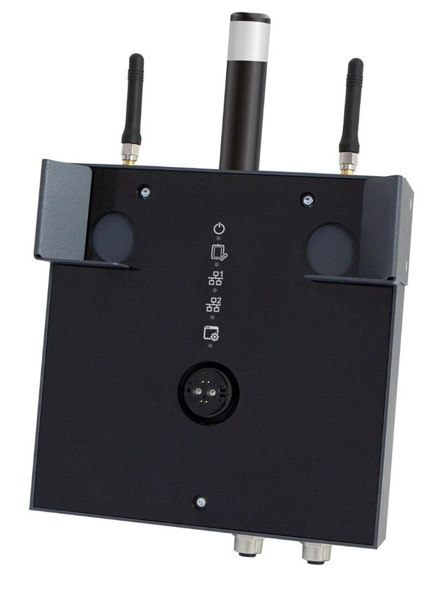
9.4.1 Ground/Shielding
The base station is grounded via the cable shielding. It is important to create a low-ohm
ground connection, only then can error-free operation be guaranteed.
It is recommended that the shielding be mounted at the entry point of the control cabinet
housing. Noise can then be deflected from the electronic components before reaching the
module.
9.4.2 ESD Protection
Before any device is connected to, or disconnected from the terminal, the
potential should be equalized (by touching the control cabinet or ground ter-
minal). Electrostatic loads (through clothing and shoes) can be thereby dis-
sipated.
Avant de connecter ou de déconnecter un appareil à la borne, le potentiel
doit être égalisé (en touchant l'armoire électrique ou la borne de terre). Les
charges électrostatiques (à travers les vêtements et les chaussures) peuvent
ainsi être éliminées.
Page 44 05.03.2020WLAN HGW BASE STATION BWH 001
10 Operation/Start-up
For safety reasons, the HGW is set to a special “delivery mode” when trans-
ported. This mode is automatically deactivated with the initial charging pro-
cess.
The operating system for the base station is stored on the microSD Card, which during oper-
ation, cannot be removed.
10.1 Standard Configuration
Ethernet
Ethernet X1 IP: 10.10.150.1 Subnet mask: 255.0.0.0
WLAN
At the time of delivery, the panel is configured as an access point and the network is acces-
sible with the following parameters.
The serial number is contained in the network name (SSID). This can be found on the reverse
side of the panel on the product label.
Example:
Serial number HGW1033-3: 12345678
SSID 2.4 GHz network: SN12345678_SIG_11
SSID 5 GHz network: SN12345678_SIG_10
Parameters Default value
SSID 2.4 GHz network SN_SIG_11
SSID 5 GHz network SN_SIG_10
Password for both networks. 12345678
IP address / mask 2.4 GHz network 192.168.2.1 / 255.255.255.0
IP address / mask 5 GHz network 192.168.1.1 / 255.255.255.0
05.03.2020 Page 45BWH 001 WLAN HGW BASE STATION
CAUTION Problems can arise if a control is connected to an IP network, which contains
modules that do not run on a SIGMATEK operating system. With such de-
vices, Ethernet packets could be sent to the control with such a high fre-
quency (i.e. broadcasts), that the high interrupt load could cause a real-time
runtime error or runtime error. By configuring the packet filter (Firewall or
Router) accordingly however, it is possible to connect a network with
SIGMATEK hardware to a third-party network without triggering the error
mentioned above.
Des problèmes peuvent survenir si un automate est connecté à un réseau IP
contenant des modules qui ne fonctionnent pas sous un système d'exploita-
tion SIGMATEK. Avec de tels dispositifs, les paquets Ethernet peuvent être
envoyés à l’automate avec une fréquence tellement élevée (càd. diffusion),
que les interruptions ainsi générées peuvent provoquer une erreur d'exécu-
tion. En configurant d’une façon appropriée le filtre de paquets (pare-feu ou
un routeur) il est toutefois possible de connecter un réseau avec le matériel
SIGMATEK à un réseau tiers sans déclencher l'erreur mentionnée ci-dessus.
10.1.1 Standard Application
In delivery condition, a minimal application is stored in the base station that allows loading an
HGW 1033-3.
10.2 Configuration
The operating panel can be configured in LASAL via the USB-C interface (Fehler! Verweis-
quelle konnte nicht gefunden werden.) or WLAN.
WARNING NEVER operate the panel without antennae. This can result in damage to
the device.
Ne JAMAIS utiliser le panneau sans antenne. Cela pourrait endommager
l'appareil.
The actual time-out configured in the SCP must be included in your risk
assessment!
Page 46 05.03.2020WLAN HGW BASE STATION BWH 001
10.3 Testing the Operating Area
CAUTION Test the function in the operating area. Ensure the operating panel can con-
trol the machine throughout the entire operating area. Perform this test using
an HGW.
Tester la fonction dans la zone d'utilisation. S'assurer que le panneau de
commande peut commander la machine dans toute la zone de travail. Effec-
tuer ce test à l'aide d'une HGW.
10.4 Operation
The BWH 001 base station needs no special handling. It is ready for operation as soon as
power is supplied and the application is started.
The process for coupling the operating panel can be found in chapter 10.4.1.
The meaning of the LED displays is described in chapter 6.4.
The IP addresses are configured using LASAL.
The BWH is coupled via the operating panel.
Please note that if in a handheld operating panel mounted in the BWH, certain functions may
be limited or it may have no function at all (e.g. key switch, confirmation switch...).
10.4.1 Coupling the Operating Panel
To couple the operating panel, a functioning WLAN connection is required.
As soon as the operator is located in the operational range of the base station or machine
with the HGW, the operating panel can be coupled with the machine. For this purpose, see
the documentation of the corresponding class.
If the operating panel has Safety functions and the base station is coupled with a safety-
related control, it is indicated via the activated 7-segment display which shows the machine
number.
WARNING To avoid faulty operation, an active operating panel can only be mounted in
the corresponding base station.
Pour éviter un fonctionnement défectueux, un panneau de commande actif
ne peut être monté que sur la station de base correspondante.
05.03.2020 Page 47BWH 001 WLAN HGW BASE STATION
10.4.2 Decoupling the Operating Panel
The operating device can be separated from the machine in several ways.
1. Separating the Safety functions only: In this case, the operating panel can be further
used as a control unit without Safety.
2. Decoupling the operating panel from the machine: The panel has no operating func-
tion and is therewith not a part of the system control unit.
3. Deactivating the WLAN connection: In this case, the panel is used offline only and
has no connection to the machine.
To avoid an emergency stop, perform a controlled decoupling of the HGW.
Page 48 05.03.2020You can also read