HGT 1053 10.1" Handheld Operating Panel - Operating Manual - SIGMATEK
←
→
Page content transcription
If your browser does not render page correctly, please read the page content below

HGT 1053
10.1" Handheld Operating Panel

                               Operating Manual

Date of creation: 23.02.2021    Version date: 24.03.2021   Article number: 01-245-1053-E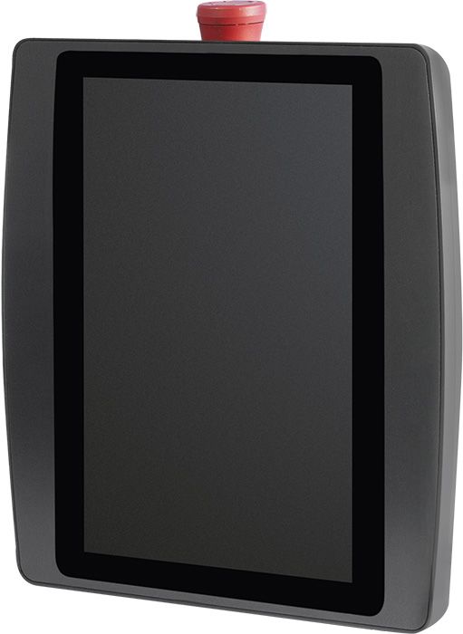
Publisher: SIGMATEK GmbH & Co KG
                                  A-5112 Lamprechtshausen
                                     Tel.: +43/6274/4321
                                   Fax: +43/6274/4321-18
                                  Email: office@sigmatek.at
                               WWW.SIGMATEK-AUTOMATION.COM

                                             Copyright © 2021
                                          SIGMATEK GmbH & Co KG

                                     Translation from German

All rights reserved. No part of this work may be reproduced, edited using an electronic system, duplicated or
distributed in any form (print, photocopy, microfilm or in any other process) without express permission.

We reserve the right to make changes in the content without notice. SIGMATEK GmbH & Co KG is not
responsible for technical or printing errors in this handbook and assumes no responsibility for damages that
occur through its use.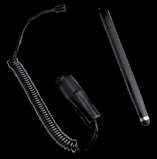
10.1" HANDHELD OPERATING PANEL            HGT 1053

10.1" Handheld Operating Panel                                             HGT 1053

The HGT 1053 is an intelligent panel for
visualizing, operating and monitoring automated
processes. Process diagnostics is therewith
simplified.
The handheld operating panel has the following
Safety components:

    l   Emergency stop switch

    l   Key switch

    l   Confirmation switch

The projected capacitive touch screen serves as
the input medium for process data and
parameters. The output is shown on a 10.1-inch
TFT color display (WXGA 800 x 1280) with LED
backlighting.
With the LASAL visualization tool, graphics can
be created on the PC, then stored and displayed on the handheld operating panel. The
available interfaces can be used to exchange process data or configure the handheld
operating panel. The operating system, application and application data are stored on the
internal storage medium.
The Safety functions can be implemented via the connection to a SCP 111.
The connector cable is optionally available with various connectors.

24.03.2021                                                                       Page 1
HGT 1053 10.1" HANDHELD OPERATING PANEL
Table of Contents
1 Introduction 6
1.1 Target Group/Purpose of this Operating Manual 6
1.2 Important Reference Documentation 6
1.3 Contents of Delivery 6
2 Basic Safety Guidelines 7
2.1 Symbols Used 7
2.2 Disclaimer 9
2.3 General Safety Guidelines 10
2.4 Designated Use 12
2.5 Software/Training 14
3 Standards and Guidelines 15
3.1 Residual Risks 15
3.2 Safety of the Machine or Equipment 15
3.3 Regular Technical Inspection of the Emergency Stop 16
3.4 Regular Technical Inspection of Safety-oriented Switches 16
3.5 Guidelines 16
3.5.1 Functional Safety Standards 16
3.5.2 EU Conformity Declaration 17
3.6 Safety-Relevant Parameters 17
4 Technical Data 18
4.1 Performance Data 18
4.2 Electrical Requirements 19
4.3 Display 20
4.4 Control Unit 21
4.5 Minimum Distance between Operating Elements for Multi-touch Applications 22
4.6 Input 22
Page 2 24.03.202110.1" HANDHELD OPERATING PANEL HGT 1053
4.7 Environmental Conditions 23
4.8 Miscellaneous 24
5 Interfaces 25
5.1 Connections Bottom 25
5.1.1 X1: USB Interface 2.0 Type A 25
5.2 Rear Connectors 26
5.2.1 X2: M16 Cable Connector 26
5.3 Status Display LEDs 27
5.4 Key Switch 28
5.5 Confirmation Switch 29
5.6 Emergency Stop 30
6 Mechanical Dimensions 31
7 Assembly/Installation 32
7.1 Check Contents of Delivery 32
7.2 Cooling 32
7.3 Wall Mount 33
8 Wiring 34
8.1 Recommended Shielding 34
8.1.1 Connection from the Control Cabinet to the HGT 1053 34
8.2 ESD Protection 35
8.3 USB Interface 35
9 Process Diagram 36
10 Status and Error Messages 37
11 Operation/Start-up 47
11.1 Note 47
11.2 Operation 47
11.2.1 General 47
24.03.2021 Page 3HGT 1053 10.1" HANDHELD OPERATING PANEL
11.2.2 Evaluating Operating Elements 49
12 Transport/Storage 50
13 Storage 51
14 Maintenance 52
14.1 Cleaning and Disinfecting the Touch Screen 52
14.2 Service 53
14.2.1 Calibrating the Touch Screen 53
14.3 Repair 54
15 Buffer Battery 55
15.1 Data Retention Battery Change 56
15.2 Exchanging the Battery 56
16 microSD Card 58
16.1 Exchanging the microSD Card 58
17 Display „Burn-In“ Effect 60
17.1 Screen Saver 60
18 Disposal 61
19 Accessories 62
19.1 Touch Pen 62
19.2 Edge Protection 62
19.3 Battery 62
20 Application Information 63
20.1 Configuring Safety Components 63
20.1.1 Minimum System Requirements 63
20.1.2 Adding the HGT 1053 to a SAFETYDesigner Project 63
20.1.3 Key Switch 63
20.1.4 Confirmation Switch 63
20.1.5 Emergency Stop 63
Page 4 24.03.202110.1" HANDHELD OPERATING PANEL HGT 1053 20.2 Storage Media 64 20.3 Updating the Operating System 65 20.4 HW Facts 65 24.03.2021 Page 5
HGT 1053       10.1" HANDHELD OPERATING PANEL

1 Introduction

1.1 Target Group/Purpose of this Operating Manual
This operating manual contains all information required for the operation of the product.
This operating manual is intended for:

    l   Project planners

    l   Technicians

    l   Commissioning engineers

    l   Machine operators

    l   Maintenance/test technicians

General knowledge of automation technology is required.
Further help and training information, as well as the appropriate accessories can be found
on our website www.sigmatek-automation.com.
Our support team is happily available to answer your questions.
Please see our website for our hotline number and business hours.

1.2 Important Reference Documentation

    l   Safety System Handbook

    l   Documentation Connection Cables for Operating Devices

    l   HW IP Address Settings

This and additional documents can be downloaded from our website or obtained through
support.

1.3 Contents of Delivery
1x HGT 1053
2x keys

Page 6                                                                          24.03.2021
10.1" HANDHELD OPERATING PANEL HGT 1053
2 Basic Safety Guidelines
2.1 Symbols Used
The following symbols are used in the operator documentation for warning and danger
messages, as well as informational notes.
DANGER
Danger indicates that death or serious injury will occur, if the
specified measures are not taken.
To avoid death or serious injuries, observe the all guidelines.
Danger indique une situation dangereuse qui, faute de prendre les
mesures adéquates, entraînera des blessures graves, voire mortelles.
Respectez toutes les consignes pour éviter des blessures
graves, voire mortelles.
WARNING
Warning indicates that death or serious injury can occur, if the
specified measures are not taken.
To avoid death or serious injuries, observe the all guidelines.
Avertissement d’une situation dangereuse qui, faute de prendre les
mesures adéquates, entraînera des blessures graves, voire mortelles.
Respectez toutes les consignes pour éviter des blessures
graves, voire mortelles.
24.03.2021 Page 7HGT 1053 10.1" HANDHELD OPERATING PANEL
CAUTION
Caution indicates that moderate to slight injury can occur, if the
specified measures are not taken.
To avoid moderate to slight injuries, observe the all guidelines.
Attention indique une situation dangereuse qui, faute de prendre les
mesures adéquates, peut entraîner des blessures assez graves ou
légères.
Respectez toutes les consignes pour éviter des blessures
graves, voire mortelles.
DANGER
Danger for persons with pacemakers, implanted defibrillators or other
active implants.
Danger pour les personnes portant un stimulateur cardiaque, un
défibrillateur implanté ou d'autres implants actifs
CAUTION
Danger for ESD-sensitive components.
Les signes de danger pour les composants sensibles aux décharges
électrostatiques.
WARNING
Magnetic field warning
Alerte au champ magnétique
INFORMATION
INFORMATION
Provides important information on the product, handling or
relevant sections of the documentation, which require
particular attention.
Page 8 24.03.202110.1" HANDHELD OPERATING PANEL HGT 1053
2.2 Disclaimer
INFORMATION
The contents of this operating manual were prepared with the greatest
care. However, deviations cannot be ruled out. This operating manual is
regularly checked and required corrections are included in the
subsequent versions. The machine manufacturer is responsible for the
proper assembly, as well as device configuration. The machine
operator is responsible for safe handling, as well as proper operation.
The current operating manual can be found on our website. If
necessary, contact our support.
Subject to technical changes, which improve the performance of the
devices. The following operating manual is purely a product description.
It does not guarantee properties under the warranty.
Please thoroughly read the corresponding documents and this
operating manual before handling a product.
SIGMATEK GmbH & Co KG is not liable for damages caused
through, non-compliance with these instructions or applicable
regulations.
24.03.2021 Page 9HGT 1053 10.1" HANDHELD OPERATING PANEL
2.3 General Safety Guidelines
The Safety Guidelines in the other sections of this operating manual must be observed.
These instructions are visually emphasized by symbols.
INFORMATION
According to EU Guidelines, the operating manual is a component of a
product.
This operating manual must therefore be accessible in the vicinity of the
machine since it contains important instructions.
This operating manual should be included in the sale, rental or transfer
of the product, or its online availability indicated.
Maintain this operating manual in readable condition and keep it
accessible for reference.
Regarding the requirements for Safety and health connected to the use
of machines, the manufacturer must perform a risk assessment in
accordance with machine guidelines 2006/42/EG before introducing a
machine to the market. Before commissioning this product, check that
conformance with the provisions of the 2006/42/EG guidelines is
correct. As long as the machine with which the product should be used
does not comply with the guideline, operating this product is prohibited.
Operate the unit with devices and accessories approved by SIGMATEK
only.
Page 10 24.03.202110.1" HANDHELD OPERATING PANEL HGT 1053
CAUTION
Handle the device with care and do not drop or let fall.
Prevent foreign bodies and fluids from entering the device.
The device must not be opened, otherwise it could be damaged!
Manipulez l’appareil avec précaution et ne le laissez pas tomber.
Empêchez les corps étrangers et les liquides de pénétrer dans
l’appareil.
L’appareil ne doit pas être ouvert, sinon il risque d’être endommagé!
Regularly check the housing for mechanical damage.
Vérifier régulièrement l’absence de dommages mécaniques sur le
boîtier.
The module complies with EN 61131-2.
In combination with a machine, the machine builder must comply with
EN 60204-1 standards.
For your own safety and that of others, compliance with the
environmental conditions is essential.
The control cabinet must be connected to ground correctly.
To perform maintenance or repairs, disconnect the system from the
power supply.
Le module est conforme à la norme EN 61131-2.
En combinaison avec une machine, le constructeur de la machine doit
respecter la norme EN 60204-1.
L’armoire de commande doit être raccordée correctement à la terre.
Pour l'entretien et les réparations, débranchez le système de
l'alimentation.
24.03.2021 Page 11HGT 1053 10.1" HANDHELD OPERATING PANEL
2.4 Designated Use
The Safety functions implemented in the Safety modules are designed for use with safety
applications in a PLC control and meet the required conditions for safe operation
according to SIL 3 in compliance with EN 62061 and according to PL e / CAT 4 in
compliance with EN ISO 13849-1.
CAUTION
The instructions contained in this operating manual must be followed.
For error-free operation, proper transport and storage are essential.
Installation, mounting, programming, initial start-up, operation,
maintenance and decommissioning can only be performed by qualified
personnel.
Qualified personnel in this context are people, who have completed
training or have trained under supervision of qualified personnel and
have been authorized to operate and maintain safety-related
equipment, systems and facilities in compliance with the strict
guidelines and standards of safety technology (Functional Safety).
Les instructions contenues dans ce manuel technique doivent être
suivies.
Pour un fonctionnement sans erreur, le transport et le stockage
appropriés sont essentiels.
L’installation, le montage, la programmation, la mise en service initiale,
l’exploitation, la maintenance et la mise hors service ne peuvent être
effectués que par une personne qualifiée.
Dans ce contexte, on entend par personnel qualifié les personnes qui
ont suivi une formation ou qui ont été formées sous la supervision d’un
per-sonnel qualifié et qui ont été autorisées à utiliser et à entretenir
l’équipement, les systèmes et les installations de sécurité
conformément aux directives et aux normes strictes de la technique de
sécurité (Sécurité fonctionnelle).
For your own safety and that of others, the safety modules should be
used for their designated purpose only.
Correct EMC installation is also included under designated use.
Pour votre propre sécurité et celle des autres, les modules de sécurité
ne doivent être utilisés qu’à des fins prévues.
Une installation CEM correcte est également incluse dans l’utilisation
prévue.
Page 12 24.03.202110.1" HANDHELD OPERATING PANEL HGT 1053
Non-designated use consists of:
l any changes made to the module or the use of damaged
modules.
l use of the module inconsistent with the technical margins
described in this operating manual or the speciation's defined
in the technical data.
L'utilisation non désignée consiste en:
l toute modification apportée au module ou l'utilisation des
modules endommagés.
l sation du module non conforme aux marges techniques
décrites dans ce manuel ou aux spécifications définies dans
les données techniques.
CAUTION
As required by EN ISO 13850, section 4.1 and EN 60204-1, section
10.7.1, confusion between a functioning and non-functioning handheld
operating panel is possible must be prevented.
Conformément à la norme EN ISO 13850, section 4.1 et EN 60204-1,
section 10.7.1, la confusion entre un panneau de commande portatif
fonctionnel et non fonctionnel doit être évitée.
If an operating panel is not coupled and not in use, keep it in a location
with restricted access.
Si un panneau de commande n'est pas couplé et n'est pas utilisé, con-
servez-le dans un endroit à accès restreint.
INFORMATION
Hardware and software features (application-specific data) can be
found in chapter 20 Application Information.
24.03.2021 Page 13HGT 1053 10.1" HANDHELD OPERATING PANEL 2.5 Software/Training The application is created with the software LASAL CLASS 2 and LASAL SCREEN Editor / VISUDesigner (HTML5), the Safety application is created using the SAFETYDesigner. Basic information on Safety (Functional Safety) can be found in the Safety System Handbook. Training for the LASAL development environment, with which the product can be configured, is provided. Information on our training schedule can be found on our website. Page 14 24.03.2021
10.1" HANDHELD OPERATING PANEL               HGT 1053

3 Standards and Guidelines

3.1 Residual Risks

                     CAUTION
                 According to the EU guideline 2006/42/EG (machine guideline), the
                 machine manufacturer must perform a risk assessment, which includes
                 the possible residual risks posed by the product. These include:

                      l   unwanted movements of driven machine components

                      l   unwanted temperatures, emissions of gas, particles, smell and
                          light

                      l   dangerous contact voltages

                      l   the effects of electrical, magnetic and electromagnetic fields
                          produced during operation (for example, on pacemakers and
                          implants)

                      l   possible effects of information technology devices (cell/smart
                          phones etc.)

                      l   release of non-environmentally compatible substances and
                          emissions

3.2 Safety of the Machine or Equipment
Strict compliance with the safety guidelines is required, otherwise all warranties and claims
are invalid.

                  INFORMATION
                 Observe all on-site rules and regulations for accident prevention and
                 occupational safety.

24.03.2021                                                                          Page 15
HGT 1053 10.1" HANDHELD OPERATING PANEL
3.3 Regular Technical Inspection of the Emergency Stop
CAUTION
The emergency stop should be regularly checked for manipulation and
damage.
L'arrêt d'urgence doit être vérifié régulièrement pour vérifier qu'il n’a pas
subi de manipulations ou de dommages.
3.4 Regular Technical Inspection of Safety-oriented Switches
CAUTION
According to the machine guideline, mechanical and electromechanical
safety-oriented components (e.g. relays, switches, etc.) must be
regularly checked for correct function.
Emergency stop switch: at least 1x/month
Key switch: at least 1x/year
Confirmation switch: at least 1x/year
Please note the requirements of your machine. Due to Type C
standards or other guidelines, requirements could differ regionally.
3.5 Guidelines
The product was constructed in compliance with the following European Union guidelines
and tested for conformity.
3.5.1 Functional Safety Standards
EN 62061:2005 SIL 3
EN ISO 13849-1:2015 PL e / CAT 4
EN ISO 13849-2:2012
Page 16 24.03.202110.1" HANDHELD OPERATING PANEL HGT 1053
3.5.2 EU Conformity Declaration
EU Declaration of Conformity
The product HGT 1053 conforms to the following European guidelines:
2006/42/EG Machine Guideline
2014/30/EU Electromagnetic Compatibility (EMC Guideline)
2011/65/EU “Restricted use of certain hazardous substances in
electrical and electronic equipment” (RoHS Guideline)
The EU Conformity Declarations are provided on the SIGMATEK website.
See Products/Downloads or use the search function and the keyword “EU
Declaration of Conformity”.
3.6 Safety-Relevant Parameters
Input Module Safety Parameters1)
HGT 1053 PFHD = 1.1E-11 (1/h)
MTTF D = 296 years
DC = 99 %
Confirmation switch B10D = 100,000
Emergency stop switch B10D = 325,000
Key switch B10D = 10,000
1) Depending on the application, the probability of failure must be determined for the included electromechanical
components based on the B10D values listed here and included in the calculation for the entire system. The Safe CPU
SCP 111 must also be calculated in.
24.03.2021 Page 17HGT 1053 10.1" HANDHELD OPERATING PANEL
4 Technical Data
4.1 Performance Data
Processor EDGE3-Technology
Processor cores 41)
Internal program and 2-GByte (DDR4)
data memory (RAM)
Internal remnant data memory 128-kByte FRAM
Internal storage device 8-GByte eMMC2)
Optional memory expansion microSD
Graphic integrated in EDGE processor
Interfaces 1x Ethernet (10/100/1000)
1x USB 2.0 Type A
1x Safety Interface
Internal interface connections and 1x TFT color display
devices 1x USB 2.0 Type A
1x USB (touch connection)
1x microSD card holder (SD 3.0)
Operating components Confirmation switch (2 normally open contacts, 3-stage)
Key switch (2 normally open contacts)
Emergency stop switch (2 normally closed contacts)
Signal generator no
Display 10.1“ TFT color display
Resolution WXGA 800 x 1280 pixels
Operating field Touch screen (multi-touch, projective capacitive)
Status LEDs Multi-LED (red/green)
Real-time clock yes (battery buffered)
Cooling semi-passive (fan activated only when required)
1) Attention: When programming on multi-core CPUs (with LASAL), particular focus must be placed on thread security!
2) The internal storage device (eMMC) is not available with HW1.0 and is implemented with an 8-Gbyte microSD card.
Starting from HW2.0, this card is no longer included with delivery, the internal storage device (eMMC) is provided.
Page 18 24.03.202110.1" HANDHELD OPERATING PANEL HGT 1053
INFORMATION
The Safety interface must be used exclusively with the SIGMATEK SCP
111! The status of the Safety-oriented inputs is sent to the SCP 111.
4.2 Electrical Requirements
Supply voltage +24 V DC ±20 % (SELV/PELV)
UL: Class 2 of LVLC
Protection class III
Current consumption of (+24 V) typically 600 mA maximum 700 mA
power supply (with no external devices (with external devices connected)
connected)
Inrush current without current- maximum 9 A for < 110 µs
limiting supply
Inrush current with 24 V/10 A maximum 1.9 A for < 500 ms
fixed voltage supply
USB current load maximum 0.5 A
The specified supply voltage refers directly to the device connection. Take the generated
voltage drop via the hybrid cable into consideration and if necessary, increase the required
supply voltage.
INFORMATION
For USA and Canada:
The supply must be limited to:
a) max. 5 A at voltages from 0-20 V DC, or
b) 100 W at voltages from 20-60 V DC
The limiting component (e.g. transformer, power supply or fuse) must be
certified by an NRTL (Nationally Recognized Testing Laboratory).
24.03.2021 Page 19HGT 1053 10.1" HANDHELD OPERATING PANEL
4.3 Display
Type 10.1” TFT color display
Resolution WXGA 800 x 1280 pixels
Color depth 24-Bit RGB
LCD mode normally black 1)
LCD Polarizer transmissive2)
Pixel size 0.1695 x 0.1695 mm
Active range 135.6 x 216.96 mm
Backlighting LED
Contrast ratio typically 800:1
Brightness typically 300 cd/m²
Angle CR ≥ 10 from all sides 85° 3)
Life span By compliance with the ambient conditions, the brightness of the display
sinks after 15,000 operating hours to 50 % of the original brightness.
Due to the manufacturing process, individual pixel errors cannot be excluded to 100 % and therefore do not constitute a
reduction in quality.
1) If there is no display data, the display remains black when the backlighting is on.
2) Display technology, with which display backlighting is used.
3) The viewing angle is measured from the normal to the display surface.
Page 20 24.03.202110.1" HANDHELD OPERATING PANEL HGT 1053
4.4 Control Unit
Touch panel projective capacitive touch panel
Cleaning see chapter: 14.1 Cleaning and Disinfecting the Touch Screen
INFORMATION
A projective capacitive touch screen is built into the panel, with which
10-finger input, zoom and gesture functions can be implemented. Data
can be input using fingers, a project capacitive touch pen as well as
with thin gloves. The device must always be grounded or, for cable-
connected devices, the ground must be correctly connected to ensure
stable operation of the touch screen. The touch function may still have
to be individually adapted to the respective environmental conditions.
24.03.2021 Page 21HGT 1053 10.1" HANDHELD OPERATING PANEL
4.5 Minimum Distance between Operating Elements for Multi-touch
Applications
To guarantee smooth operation with multi-touch applications, buttons and control elements
that should be operated at the same time must have a realistic minimum clearance.
INFORMATION
The size of the buttons and operating elements directly affect the
operability of the application. Small operating elements should
therefore be avoided.
4.6 Input
Input Multi-touch screen (PCAP)
Page 22 24.03.202110.1" HANDHELD OPERATING PANEL HGT 1053
Emergency stop switch 1
Confirmation switch 1 (3 switch positions with panic function)
Key switch 1 (2 switch positions)
4.7 Environmental Conditions
Storage temperature -10 ... +70 °C
Environmental temperature 0 ... +50 °C
Humidity 10-95 %, non-condensing
Installation altitude above sea 0-2000 m without derating
level
> 2000 m up to a maximum of 5000 m with derating of the maximum
environmental temperature by 0.5 °C per 100 m
Operating conditions pollution degree 2
EMC resistance according to EN61000-6-2 (industrial area)
(increased requirements according to EN 62061)
EMC noise generation according to EN 61000-6-3 (Household area)
according to EN 61000-6-4 (industrial area)
Vibration resistance EN 60068-2-6 5-150 Hz: amplitude 3.5 mm
transition frequency: 8.42454 Hz
acceleration: 1 g
duration: 10 cycles
cycle: 1 octave/minute
Shock resistance EN 60068-2-27 15 g (147.15 m/s 2)
Protection type EN 60529 IP54
protection through housing (only with all protective in place)
Free fall DIN EN 60068-2-31 1000 mm
(with rough handling)
Free fall IEC 60068-2-32 1000 mm
(with packaging)
24.03.2021 Page 23HGT 1053 10.1" HANDHELD OPERATING PANEL 4.8 Miscellaneous Article number 01-245-1053 Hardware version 1.x Operating system Gecko Approvals CE, TÜV-Austria EG-type-examined Page 24 24.03.2021
10.1" HANDHELD OPERATING PANEL                     HGT 1053

5 Interfaces

5.1 Connections Bottom

5.1.1 X1: USB Interface 2.0 Type A

                                     Pin                        Function
                                      1                   +5 V, I out,max = 500 mA
                                      2                             D-
                                      3                             D+
                                      4                            GND

                INFORMATION
               It should be noted that many of the USB devices on the market do not
               comply with USB specifications; this can lead to device malfunctions.
               This may cause the device to malfunction. It is also possible that these
               devices will not be detected at the USB port or function correctly. It is
               therefore recommended that every USB stick or USB supply be tested
               before actual use.

24.03.2021                                                                            Page 25
HGT 1053 10.1" HANDHELD OPERATING PANEL
5.2 Rear Connectors
5.2.1 X2: M16 Cable Connector
Pin Wire color Function
L yellow Safety interface H
J green Safety interface L
G black Safety interface shield
E red +24 V DC
C black GND
A shield ETH shield
U white DA+/TX+
T red DD+
S blue DD-
R pink Gigabit DC-
P grey Ethernet DC+
O yellow DB-/RX-
N green DB+/RX+
M brown DA-/TX-
Page 26 24.03.202110.1" HANDHELD OPERATING PANEL HGT 1053
INFORMATION
Appropriate connector cables are optionally available. See
documentation for operating device connection cables.
5.3 Status Display LEDs
Multi-LED Status
Lights green - Supply voltage OK
- During operating system start
- Application running
Lights red - Supply voltage NOT OK
Lights yellow - Supply voltage OK
- Operating system not started or still in Start mode
Blinks red - Application error or reset
INFORMATION
Within the application, the multi-LED (green/red) can be controlled as
desired.
24.03.2021 Page 27HGT 1053 10.1" HANDHELD OPERATING PANEL 5.4 Key Switch The key switch is two-stage and evaluated via the SCP 111 connected to the HGT 1053. For application info, see 20.1.3 Key Switch. Page 28 24.03.2021
10.1" HANDHELD OPERATING PANEL                HGT 1053

5.5 Confirmation Switch
The confirmation switch is three stage. If the switch is not pressed or pressed only partially,
it is inactive. The switch is active when “simply” pressed (middle stage). For application
info, see 20.1.4 Confirmation Switch.

                     CAUTION
                 Activating the confirmation switch is a deliberate action. Do not press
                 the confirmation switch for longer than required to confirm the affected
                 operation.

                 The confirmation switch is part of the safety-related feature. Only the
                 person activating the confirmation switch may work in the danger zone.

The confirmation switch can be operated with the hand used to hold the operating panel.
The confirmation switch can be used as dead-man switch with a panic function.

24.03.2021                                                                           Page 29
HGT 1053 10.1" HANDHELD OPERATING PANEL 5.6 Emergency Stop The emergency stop has 2-channel construction. For application info see 20.1.5 Emergency Stop. Page 30 24.03.2021
10.1" HANDHELD OPERATING PANEL          HGT 1053

6 Mechanical Dimensions

  Dimensions                      226 x 264 x 76 mm (W x H x D)

  Material                             Housing: PC/ASA
                                        Color: RAL7024
                                      Front: glass 1.1 mm

  Weight                                     1.25 kg

24.03.2021                                                         Page 31
HGT 1053 10.1" HANDHELD OPERATING PANEL
7 Assembly/Installation
7.1 Check Contents of Delivery
Ensure that the contents of the delivery are complete and intact. See chapter 1.3 Contents
of Delivery.
INFORMATION
On receipt and before initial use, check the device for damage. If the
device is damaged, contact our customer service and do not install the
device in your system.
Damaged components can disrupt or damage the system.
7.2 Cooling
The high performance processor of the HGT 1053 is cooled passively.
The CPU is passively cooled until a critical core temperature is reached (mostly caused by
a high CPU/GPU load and simultaneously, high ambient temperatures) The fan remains
active until the CPU is cooled to a temperature that allows passive cooling. The device can
therefore reliably operate at full capacity without performance loss at the maximum
operating temperature and extend the lifespan of the the fan during idle times.
A fan is with a very high life expectancy is installed.
Life expectancy (continuous operation, fan)
MTTF (MTBF) at 40 °C 550 000 h = circa 62 years
L10 at 40 °C 70 000 h = circa 8 years
The speed and status of the fan can be read via the device software (hardware class). A
fan monitor can be thereby implemented, which warns the user of a defect.
Page 32 24.03.202110.1" HANDHELD OPERATING PANEL HGT 1053 7.3 Wall Mount Using the corresponding wall mount, the panel can be attached to the provided holder (A1) on the back (see dimensions for counter piece). 24.03.2021 Page 33
HGT 1053       10.1" HANDHELD OPERATING PANEL

8 Wiring

8.1 Recommended Shielding
For applications in which the bus is operated outside the control cabinet, the correct
shielding is required. This is especially important, if due to physical requirements, the bus
cables must be placed next to sources of strong electromagnetic noise. It is recommended
that wiring the connector cable in parallel with power cables be avoided whenever
possible.

8.1.1 Connection from the Control Cabinet to the HGT 1053

It is recommended that the shielding be mounted at the entry point of the control cabinet
housing. Noise can then be deflected from the electronic components before reaching the
module.

                                    Schematic Representation

Page 34                                                                          24.03.2021
10.1" HANDHELD OPERATING PANEL HGT 1053
8.2 ESD Protection
CAUTION
Typically, USB devices (keyboard, mouse etc.) are equipped with non-
shielded cables. These devices are disrupted by ESD and in some
instances, no longer function.
Généralement, les périphériques USB (clavier, souris etc) ne sont pas
équipés de câbles blindés. Ces dispositifs sont perturbés par des
décharges électrostatiques et, dans certains cas, ne fonctionnent plus.
Before any device is connected to, or disconnected from the product,
the potential should be equalized (by touching the control cabinet or
ground terminal). Electrostatic loads (through clothing and shoes etc.)
can thereby be dissipated.
Avant de connecter ou de déconnecter un appareil à le produit, le
potentiel doit être égalisé (en touchant l'armoire électrique ou la borne
de terre). Les charges électrostatiques (à travers les vêtements et les
chaussures etc.) peuvent ainsi être éliminées.
8.3 USB Interface
The product has a USB interface. This interface can be used to connect various USB
devices (keyboard, mouse, storage media, hubs, etc.). Several USB devices can be
connected using a hub, which are then fully functional.
24.03.2021 Page 35HGT 1053 10.1" HANDHELD OPERATING PANEL 9 Process Diagram Page 36 24.03.2021
10.1" HANDHELD OPERATING PANEL                                 HGT 1053

10 Status and Error Messages
Status and error messages are shown in the status test of the LASAL CLASS software.
POINTER or CHKSUM messages can also be shown on the screen.

  Number     Message                 Definition                      Cause/Solution

     00      RUN RAM                 The user program is             Info
                                     currently running in RAM.
                                     The display is not
                                     affected.

     01      RUN ROM                 The user program stored         Info
                                     in the program memory
                                     module was loaded into
                                     the RAM and is currently
                                     running. The display is not
                                     affected.

     02      RUNTIME                 The total time for all cyclic   Optimize the application's cyclic
                                     objects exceeds the             task.
                                     maximum time; the time          Use higher capacity CPU.
                                     can be configured using 2       Configure preset value
                                     system variables:
                                     n   Runtime: Remaining
                                         time
                                     n   SWRuntime: Preset
                                         value for runtime
                                         counter

     03      POINTER                 Incorrect program               Possible Causes:
                                     pointers were detected          n      The program memory module is
                                     before running the user                missing, not programmed or
                                     program                                defective.
                                                                     n      The program in the user
                                                                            program memory (RAM) is not
                                                                            executable.
                                                                     n      The buffer battery has failed.
                                                                     n      The user program has
                                                                            overwritten a software error.

                                                                     Solution:
                                                                     n      Reprogram the memory
                                                                            module, if the error reoccurs
                                                                            exchange the module.
                                                                     n      Exchange the buffering battery
                                                                     n      Correct programming error

24.03.2021                                                                                          Page 37
HGT 1053 10.1" HANDHELD OPERATING PANEL
Number Message Definition Cause/Solution
04 CHKSUM An invalid checksum was Cause/Solution: s. POINTER
detected before running
the user program.
05 WATCHDOG The program was Possible Causes:
interrupted via the n User program interrupts
watchdog logic. blocked over a longer period of
time (STI command forgotten).
n Programming error in a
hardware interrupt.
n INB, OUTB, INW, OUTW
instructions used incorrectly.
n The processor is defective.
Solution:
n Correct programming error.
n Exchange CPU
06 GENERAL ERROR General error This error occurs only during the
An error has occurred development of the operating
while stopping the system.
application via the online
interface.
07 PROM DEFECT An error has occurred Causes:
while programming the n The program memory module is
memory module. defective.
n The user program is too large.
n The program memory module is
missing.
Solution:
n Exchange the program memory
module
08 RESET The CPU has received Info
the reset signal and is
waiting for further
instructions.
The user program is not
processed.
Page 38 24.03.202110.1" HANDHELD OPERATING PANEL HGT 1053
Number Message Definition Cause/Solution
09 WD DEFECT The hardware monitoring Solution:
circuit (watchdog logic) is n Exchange CPU
defective.
After power-up, the CPU
checks the watchdog
logic function. If an error
occurs during this test,
the CPU deliberately
enters an infinite loop
from which no further
instructions are accepted.
10 STOP The program was stopped
by the programming
system.
11 PROG BUSY Reserved
12 PROGRAM LENGTH Reserved
13 PROG END A memory module was Info
successfully
programmed.
14 PROG MEMO The CPU is currently Info
programming the memory
module.
15 STOP BRKPT The CPU was stopped by Info
a breakpoint in the
program.
16 CPU STOP The CPU was stopped by Info
the programming
software.
17 INT ERROR The CPU has triggered a Causes:
false interrupt and n A nonexistent operating system
stopped the user program was used.
or has encountered an
n Stack error (uneven number of
unknown instruction while
PUSH and POP instructions).
running the program.
n The user program was
interrupted by a software error.
Solution:
n Correct programming error.
24.03.2021 Page 39HGT 1053 10.1" HANDHELD OPERATING PANEL
Number Message Definition Cause/Solution
18 SINGLE STEP The CPU is in single step Info
mode and is waiting for
further instructions.
19 READY: A module or project has Info
been sent to the CPU and
it is ready to run the
program.
20 LOAD The program is stopped Info
and the CPU is currently
receiving a new module or
project.
21 INVALID MODULE The CPU has received a Solution:
module that does not n Recompile and download the
belong to the project. entire project
22 MEMORY FULL The operating system Causes:
memory (heap) is too n Memory is only allocated but
small. No memory could not released.
be reserved while calling
an internal function or an Solution:
interface function is called
n Clear memory
from the application.
23 NOT LINKED When starting the CPU, a Solution:
missing module or a n Recompile and download the
module that does not entire project
belong to the project was
detected.
24 DIV BY 0 A division error has Possible Causes:
occurred. n Division by 0.
n The result of a division does not
fit in the result register.
Solution:
n Correct programming error.
25 DIV BY 0 A division error has Possible Causes:
occurred. n Division by 0.
n The result of a division does not
fit in the result register.
Solution: Correct programming
error.
Page 40 24.03.202110.1" HANDHELD OPERATING PANEL HGT 1053
Number Message Definition Cause/Solution
25 DIAS ERROR While accessing a DIAS Hardware problem
module, an error has
occurred.
26 WAIT The CPU is busy. Info
27 OP PROG The operating system is Info
currently being
reprogrammed.
28 OP INSTALLED The operating system has Info
been reinstalled.
29 OS TOO LONG The operating system Restart, report error to SIGMATEK.
cannot be loaded; too little
memory.
30 NO OPERATING SYSTEM Boot loader message, no Restart, report error to SIGMATEK.
operating system found in
RAM.
31 SEARCH FOR OS The boot loader is Restart, report error to SIGMATEK.
searching for the
operating system in RAM.
32 NO DEVICE Reserved
33 UNUSED CODE Reserved
34 MEM ERROR The operating system Solution:
loaded does not match n Use the correct operating
the hardware system version
configuration.
35 MAX IO Reserved
36 MODULE LOAD ERROR The LASAL Module or Solution:
project cannot be loaded. n Recompile and download the
entire project
37 BOOTIMAGE FAILURE A general error has Contact SIGMATEK
occurred while loading the
operating system.
38 APPLMEM ERROR An error has occurred in Solution:
the application memory n Correct allocated memory
(user heap). access error
24.03.2021 Page 41HGT 1053 10.1" HANDHELD OPERATING PANEL
Number Message Definition Cause/Solution
39 OFFLINE This error does not occur This error code is used in the
in the control. programming system to show that
there is no connection to the control.
40 APPL LOAD Reserved
41 APPL SAVE Reserved
44 VARAN MANAGER ERROR An error number was Solution:
entered in the VARAN n Read LogFile
manager and stopped the
program.
45 VARAN ERROR A required VARAN client Solution:
was disconnected or a n Read LogFile error tree
communication error has
occurred.
46 APPL-LOAD-ERROR An error has occurred Cause:
while loading the n Application was deleted.
application.
Solution:
n Reload the application into the
control.
47 APPL-SAVE-ERROR An error has occurred
while attempting to save
the application.
50 ACCESS-EXCEPTION- Read or write access of a Solution:
ERROR restricted memory area. n Correct application errors
(I.e. writing to the NULL
pointer).
51 BOUND EXCEEDED An exception error has Solution:
occurred while accessing n Correct application errors
arrays. The memory area
was overwritten by
accessing an invalid
element.
52 PRIVILEDGED An unauthorized Cause:
INSTRUCTION instruction for the current n The application has overwritten
CPU level was given. For the application program code.
example, setting the
segment register. Solution:
n Correct application errors
Page 42 24.03.202110.1" HANDHELD OPERATING PANEL HGT 1053
Number Message Definition Cause/Solution
53 FLOATING POINT ERROR An error has occurred
during a floating-point
operation.
60 DIAS-RISC-ERROR Error from the Intelligent Restart, report error to SIGMATEK.
DIAS Master.
64 INTERNAL ERROR An internal error has Restart, report error to SIGMATEK.
occurred, all applications
are stopped.
65 FILE ERROR An error has occurred
during a file operation.
66 DEBUG ASSERTION Internal error Restart, report error to SIGMATEK.
FAILED
67 REALTIME RUNTIME The total duration of all Solution:
real-time objects exceeds n Optimize the application's real-
the maximum time; the time task (RtWork).
time cannot be
n Reduce the clock time for the
configured. 2 ms for 386
real-time task of all objects.
CPUs, 1 ms for all other
CPUs n Correct application errors
n CPU is overloaded in real-time
=> use a higher capacity CPU.
68 BACKGROUND RUNTIME The total time for all Solution:
background objects n Optimize the application's
exceeds the maximum background task (background)
time; the time can be
n Use higher capacity CPU
configured using 2
system variables: - n Set SWBTRuntime correctly
BTRuntime: -
SWBTRuntime: pre-
selected value for the
runtime counter
70 C-DIAS ERROR A connection error with a Cause:
C-DIAS module has n The cause of the error is
occurred. documented in the log file
Solution:
n This depends on the cause
24.03.2021 Page 43HGT 1053 10.1" HANDHELD OPERATING PANEL
Number Message Definition Cause/Solution
72 S-DIAS ERROR A connection error with an Possible Causes:
S-DIAS module has n Real network does not match
occurred. the project, S-DIAS client is
defective
Solution:
n Analyze log file
75 SRAM ERROR An error occurred while Possible Causes:
initializing, reading or n SRAM configured incorrectly
writing SRAM data.
n Battery for powering the internal
program memory is empty
Solution:
n Analyze log file (Event00.log,
Event19.log)
n Check configuration
n Exchange battery for powering
the internal program memory
95 USER DEFINED 0 User-definable code.
96 USER DEFINED 1 User-definable code.
97 USER DEFINED 2 User-definable code.
98 USER DEFINED 3 User-definable code.
99 USER DEFINED 4 User-definable code.
100 C_INIT Initialization start; the
configuration is run.
101 C_RUNRAM The LASAL project was
successfully started from
RAM.
102 C_RUNROM The LASAL project was
successfully started from
ROM.
103 C_RUNTIME
104 C_READY The CPU is ready for
operation.
105 C_OK The CPU is ready for
operation.
Page 44 24.03.202110.1" HANDHELD OPERATING PANEL HGT 1053
Number Message Definition Cause/Solution
106 C_UNKNOWN_CID An unknown object from a
stand-alone or embedded
object, or an unknown
base class was detected.
107 C_UNKNOWN_CONSTR The operating system
class cannot be created;
the operating system is
probably wrong.
108 C_UNKNOWN_OBJECT Indicates an unknown
object in an interpreter
program; more the one
DCC080 object.
109 C_UNKNOWN_CHNL The hardware module
number is greater than 60.
110 C_WRONG_CONNECT No connection to the
required channels.
111 C_WRONG_ATTR Wrong server attributes.
112 C_SYNTAX_ERROR Non-specific error.
Recompile and download
all project sections.
113 C_NO_FILE_OPEN An attempt was made to
open an unknown table.
114 C_OUTOF_NEAR Memory allocation failed
115 C_OUT OF_FAR Memory allocation failed
116 C_INCOMAPTIBLE An object with the same
name already exists but
has a different class.
117 C_COMPATIBLE An object with the same
name and class exists but
must be updated.
224 LINKING The application is
currently linking.
225 LINKING ERROR An error has occurred
while linking.
226 LINKING DONE Linking is complete.
24.03.2021 Page 45HGT 1053 10.1" HANDHELD OPERATING PANEL
Number Message Definition Cause/Solution
230 OP BURN The operating system is
currently being burned
into the Flash memory.
231 OP BURN FAIL An error has occurred
while burning the
operating system.
232 OP INSTALL The operating system is
currently being installed.
240 USV-WAIT The power supply was
disconnected; the UPS is
active. The system is
shutdown.
241 REBOOT The operating system is
restarted.
242 LSL SAVE
243 LSL LOAD
252 CONTINUE
253 PRERUN The application is started.
254 PRERESET The application is ended.
255 CONNECTION BREAK
Page 46 24.03.202110.1" HANDHELD OPERATING PANEL HGT 1053
11 Operation/Start-up
11.1 Note
WARNING
The operating panel can be mounted onto magnetic components, for
example, directly on the machine.
Caution must be taken to ensure that no magnetically sensitive objects
are located in the immediate vicinity of the HGT 1053 (e.g. credit /
magnetic stripe cards).
Le panneau de commande peut être monté sur des composants
magnétiques, par exemple directement sur la machine.
Veiller à ce qu'aucun objet magnétiquement sensible ne se trouve à
proximité immédiate de HGT 1053 (p. ex. cartes de crédit / cartes à
bande magnétique).
DANGER
This device is equipped strong magnets, which can pose a danger to
people with implants such as pacemakers!
Cet appareil est équipé d'aimants puissants, ce qui peut représenter un
danger pour les personnes porteuses d'implants tels que les
stimulateurs cardiaques!
11.2 Operation
11.2.1 General
The Safety functions (key switch, confirmation switch, emergency stop) are not functional at
the time of delivery and must be defined by the applications engineer via programming. In
order to use the Safety functions, a safety-related SCP 111 CPU is required. See chapter
20 Application Information.
The HGT 1053 is operated via the touch screen.
24.03.2021 Page 47HGT 1053 10.1" HANDHELD OPERATING PANEL
INFORMATION
To avoid damage to the touch screen, it can only be operated using the
fingers or an appropriate stylus. Suitable gloves are also permitted for
the touch technology, as long as they do not damage the device (e.g.
via chips, pointed or similar objects).
CAUTION
Do not lay the operating panel on its touch screen. Also avoid laying
anything on top of the touch screen.
This can cause operating errors, undesired triggering of functions or
damage to the device.
Ne posez pas le panneau de commande sur son écran tactile. Évitez
également de poser quoi que ce soit sur l'écran tactile.Cela peut
entraîner des erreurs de fonctionnement, des déclenchements
intempestifs de fonctions ou des dommages sur l'appareil
Do not place the panel on loose or unstable surfaces. It could fall onto
the floor and be subsequently damaged.
Ne placez pas le panneau sur des surfaces lâches ou instables. Il
pourrait tomber sur le sol et être endommagé par la suite.
The operating panel is constructed to that it can be operated by right and left handers
equally.
Page 48 24.03.202110.1" HANDHELD OPERATING PANEL HGT 1053
CAUTION
Typically, USB devices (keyboard, mouse etc.) are equipped with non-
shielded cables. These devices are disrupted by ESD and in some
instances, no longer function.
Généralement, les périphériques USB (clavier, souris etc) ne sont pas
équipés de câbles blindés. Ces dispositifs sont perturbés par des
décharges électrostatiques et, dans certains cas, ne fonctionnent plus.
Before any device is connected to, or disconnected from the product,
the potential should be equalized (by touching the control cabinet or
ground terminal). Electrostatic loads (through clothing and shoes etc.)
can thereby be dissipated.
Avant de connecter ou de déconnecter un appareil à le produit, le
potentiel doit être égalisé (en touchant l'armoire électrique ou la borne
de terre). Les charges électrostatiques (à travers les vêtements et les
chaussures etc.) peuvent ainsi être éliminées.
11.2.2 Evaluating Operating Elements
The operating panel sends all statuses to the control, through which further actions can be
set. Display (display, LEDs...) are initiated by the control.
The HGT 1053 sends the following operating element statuses to the safety-related control
SCP 111, which can evaluate and process the information.
l Key switch
l Emergency stop
l Confirmation switch
24.03.2021 Page 49HGT 1053 10.1" HANDHELD OPERATING PANEL
12 Transport/Storage
INFORMATION
This device contains sensitive electronics. During transport and storage,
high mechanical stress must therefore be avoided.
For storage and transport, the same values for humidity and vibration as
for operation must be maintained!
Temperature and humidity fluctuations may occur during transport.
Ensure that no moisture condenses in or on the device, by allowing the
device to acclimate to the room temperature while turned off.
Page 50 24.03.202110.1" HANDHELD OPERATING PANEL HGT 1053
13 Storage
INFORMATION
When not in use, store the device according to the storage conditions.
See chapter 12 Transport/Storage.
During storage, ensure that all protective covers (if available) are
placed correctly, so that no contamination, foreign bodies or fluids enter
the device.
The existing battery in the device must be replaced after approx. 20
years. If the device is to be stored longer, the battery must be removed
to prevent leakage.
24.03.2021 Page 51HGT 1053 10.1" HANDHELD OPERATING PANEL
14 Maintenance
INFORMATION
During maintenance as well as servicing, observe the safety
instructions from chapter 2 Basic Safety Guidelines.
Lors de l'entretien et de la maintenance, respectez les consignes de
sécurité du chapitre 2 Basic Safety Guidelines.
14.1 Cleaning and Disinfecting the Touch Screen
CAUTION
Before cleaning and disinfecting the touch screen, it must first be
deactivated; either by turning off the terminal or by disabling the touch
screen via the application to avoid unintentionally activating functions or
commands!
Avant de nettoyer et de désinfecter l'écran tactile, il faut d'abord le
désactiver; soit en éteignant le terminal, soit en désactivant l'écran
tactile via l'application pour éviter d'activer involontairement des
fonctions ou des commandes!
The touch screen can only be cleaned with a soft, damp cloth. To dampen the cloth, a mild
cleaning solution such as antistatic foam cleaner is recommended. To avoid
fluids/cleaning solutions from getting into the housing, the device must not be sprayed
directly. To clean, no erosive cleaning solutions, chemicals, abrasive cleansers or hard
objects that can scratch or damage the touch screen may be used. The use of steam jets or
compressed air is prohibited.
For disinfection, surface disinfectants on alcohol basis, which do not contain re-fattening
agents, can be used. The disinfectant used must not leave any residues on the touch
screen to ensure proper functioning of the touch screen.
Page 52 24.03.202110.1" HANDHELD OPERATING PANEL HGT 1053
WARNING
If the device is contaminated with toxic or erosive chemicals, it must be
carefully cleaned as quickly as possible to prevent personal injury and
machine damage!
Si l’appareil est contaminé par des produits chimiques toxiques ou
érosifs, il doit être soigneusement nettoyé le plus rapidement possible
afin d'éviter des dommages corporels et matériels!
INFORMATION
To ensure the optimal function of the device, the touch screen should be
cleaned at regular intervals!
14.2 Service
This product was constructed for low-maintenance operation.
14.2.1 Calibrating the Touch Screen
The touch screen is calibrated at the factory. You should therefore only recalibrate the
touch screen when press-point changes are noticed.
This can be achieved via the following command (depending on the operating system) or
the application, if the application engineer has provided the option.
calib
24.03.2021 Page 53HGT 1053 10.1" HANDHELD OPERATING PANEL
14.3 Repair
INFORMATION
When sent for repair, the device should be transported in the original
packaging if possible. Otherwise, packaging should be selected that
sufficiently protects the product from external mechanical influences.
Such as cardboard filled with air cushioning.
CAUTION
Danger of injury from damaged components!
Damage to the device, especially the touch screen, poses a
cut hazard. In such a case, use safety gloves.
Risque de blessure par des composants endommagés !
Les dommages à l'appareil, en particulier à l'écran tactile,
présentent un risque de coupure. Dans ce cas, utilisez des
gants de sécurité.
In the event of a defect/repair, send the device with a detailed error description to the
address listed at the beginning of this document.
Page 54 24.03.202110.1" HANDHELD OPERATING PANEL HGT 1053
15 Buffer Battery
A Lithium battery is installed at the manufacturer.
The battery has enough capacity to preserve data in the absence of a supply voltage for up
to circa 20 years.
COMPANY DATA
Lithium battery RENATA 3.0 V/235 mAh
INFORMATION
Battery order number: 01-690-055
Use type CR2032 batteries from RENATA only.
Disconnect the device from the supply before changing the battery.
WARNING
Danger of fire and explosion!
Slight to serious injuries can occur from incorrect use of the
battery.
Do not recharge, disassemble or throw batteries into fire!
Danger d'incendie et d'explosion !
Des blessures légères à graves peuvent résulter d'une
mauvaise utilisation de la batterie.
Ne pas recharger, démonter ou jeter les piles dans le feu!
24.03.2021 Page 55HGT 1053 10.1" HANDHELD OPERATING PANEL
15.1 Data Retention Battery Change
The exchangeable buffer battery ensures that the following data is preserved in the
absence of a supply voltage:
l Time
If the battery is empty, the following settings are reset or data is deleted:
l Time (reset to default value)
15.2 Exchanging the Battery
1. Turn off the device supply.
2. Create ESD-compliant conditions
3. Remove the locking screws with a Torx
screwdriver.
4. Carefully lift the cover to avoid damaging the connecting cable between the
housing sections and access the battery holder.
Page 56 24.03.202110.1" HANDHELD OPERATING PANEL HGT 1053
5. Remove the battery from the holder.
6. Install the new battery with the correct polarity (+ pole facing up, away from the
circuit board).
7. Close the cover (caution, connecting cable )and tighten the locking screws (0.2
Nm).
24.03.2021 Page 57HGT 1053 10.1" HANDHELD OPERATING PANEL
16 microSD Card
The 10.1" Handheld Operating Panel is delivered with a microSD card (HW1.X). This
should only be exchanged when absolutely necessary (defective, etc.)
16.1 Exchanging the microSD Card
1. Turn off the device supply.
2. Create ESD-compliant conditions
3. Remove the locking screws with a Torx
screwdriver.
4. Carefully lift the cover to avoid damaging the connecting cable between the
housing sections and access the microSD holder. The card holder is located below
the fan.
Page 58 24.03.202110.1" HANDHELD OPERATING PANEL HGT 1053
5. Carefully press the lock on the side
(caution: card springs out due to
mechanism).
6. Remove card.
7. Insert the new microSD card.
8. Ensure that the latch is completely
engaged.
10. Close the cover (caution, connecting cable ) and tighten the locking screws (0.2
Nm).
24.03.2021 Page 59HGT 1053 10.1" HANDHELD OPERATING PANEL
17 Display „Burn-In“ Effect
The “Burn-In” effect describes a pattern burned into the display after displaying the same
contents over a longer period of time (e.g. a single screen).
This effect is also described mostly as “image sticking”, “memory effect/sticking” or “ghost
image”.
Here, a distinction is made between a temporary and permanent effect, while the
temporary effect is eliminated by switching off the screen for a longer period of time or by
displaying dynamic content, serious cases of burn-in can lead to permanent damage to the
display.
This effect can have the following causes:
l Operation without a screen saver
l The same contents displayed over a longer time period (e.g. a single screen)
l Operation at high environmental temperatures
l Operation above specifications
The effect can be avoided/reduced by the following actions:
l Using a screen saver
l Deactivating the display when not in use (e.g. screen display black)
l Continuously changing screen content (e.g. video)
INFORMATION
Deactivating the display backlighting only does not prevent Burn-In!
17.1 Screen Saver
The device has an integrated screen saver, which is activated by default and turns off the
screen after 60 minutes of inactivity. The screen can be reactivated with an input via the
touch screen or a USB operating device. The wait time for the screen saver can be
adjusted in the application via the HW class. This change is only active as long as the
device is running the application, in Reset mode, the 60-minute default setting is restored.
Page 60 24.03.2021You can also read