Control system Underfloor heating & cooling - WAVIN SENTIO Quick Guide | January 2020
←
→
Page content transcription
If your browser does not render page correctly, please read the page content below
WAVIN SENTIO
Quick Guide | January 2020

Control system
Underfloor heating
& cooling
B       D                                   B                   B

    A       C       E                           A                   A

F

                                                    G                   O
    G       H       K                           F       H   K       H

                        I       J   L   M   N

                            L                                   L

                            N                                   N

                                                                            A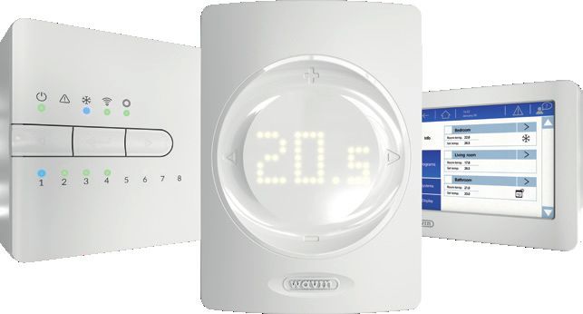
13

         1     2          3          4          5              6               7          8     9          10    11 12       14     15      16     17      18

      T1       T2         T3         T4         T5       S1 C S2 S3 C S4 01 GN 02 GN +U A B GN AO GN P0 P1

                                                                                                                             VFR1   VFR2   P1 N PE P2 N PE L N PE

                   A1         A2         A3         A4         A5         A6         A7   A8

                                                     19                                                         20 20

         20                          21                                                          20
                                                                                               26 26

    A9       A10        A11        A12        A13        A14        A15        A16             A (24V) B          C      D     E      F

    +U A B GN                                                                                  +U A B GN

         10                          20                                                             10            22    23    24     25

B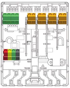
GENERAL GENERAL
GENERAL
LOWGENERAL
BATTERY
LOW BATTERY
LOW BATTERY
LOW BATTERY GENERAL GENERAL
GENERAL
LOST
GENERAL
OF LOST OF
LOST OF
LOST OF
CONNECTION
CONNECTION
CONNECTION
CONNECTION
WIRELESS WIRELESS
WIRELESS
WIRELESS
FLOOR HEATING
FLOORFLOOR
HEATING
HEATING/
FLOOR
HEATINGCOOLING
HEATING
HEATING/
HEATING/
COOLING
HEATING/
COOLINGCOOLING
DEW POINT DEW POINT
DEW POINT
DEW POINT BUS POWERED
BUS POWERED
BUS POWERED
ENROLL
BUS POWERED
PROCESS
ENROLLENROLL
PROCESS
ENROLL
PROCESS
PROCESS
BLOCKED BY
BLOCKED
FLOOR
BLOCKED
BYBLOCKED
FLOOR
BLOCKED
BY FLOOR
BY
BLOCKED
BY
WINDOW
FLOOR
BLOCKED
BY WINDOW
BLOCKED
BY WINDOW
BY WINDOW DEVICE DEVICE
DEVICE
NOT SUCCESFUL
DEVICE
NOT SUCCESFUL
NOT SUCCESFUL
NOT SUCCESFUL
SECURITY LIMIT
SECURITY
SECURITY
LIMIT
SECURITY
LIMIT LIMIT
How to replace the batteries
TOO LOW TOO LOW
TEMPERATURE
TOO LOW
TEMPERATURE
TOO
TOO
TEMPERATURE
HIGH
LOWTOO HIGH
TEMPERATURE
TEMPERATURE
TOO HIGH
TEMPERATURE
TOO HIGH
TEMPERATURE
TEMPERATURE
CheckCheck
manual
Check
Check
manual
manual
manual CheckCheck
manual
Check
Check
manual
manual
manual
Wall mounted | wireless
How to
Howreplace
How
toHow
replace
to replace
batteries
to replace
batteries
batteries
batteries
Open Replace batteries Close
WALLWALL
WALL
WALL Open Open
OpenOpen Replace
Replace
batteries
Replace
Replace
batteries
batteries
batteries Close Close
Close
Close
CLICK CLICKCLICKCLICK CLICK CLICKCLICKCLICK
AA
AA
AA
AA
AA
AA
AA
AA
Hand Held | wireless
Open Insert batteries Close
CLICK CLICKCLICKCLICK
C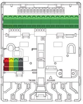
List of content

    English       page      1- 8

    Danish        page    9 - 16

    French        page   17- 24

    Italian       page   25 - 32

    German        page   33 - 40

    Polish        page   41- 48

                                   D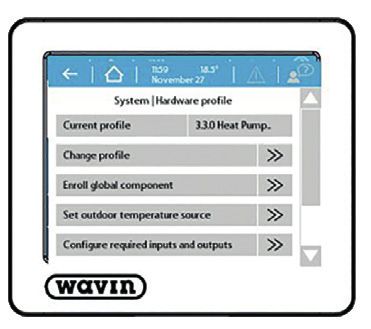
Overview of all components

                 I                            II                          III                 IV

    Art.nr.: 3077000, 3077001,   Art.nr.: 3077002, 3077003   Art.nr.: 4063803    Art.nr.: 4063796, 4063799,
    3077004                                                                      4063797,4063798, 4064446

                 V                            VI                         VII                 VIII

    Art.nr.:4063800             Art.nr.: 4
                                           063801           Art.nr.: 4
                                                                       063802   Art.nr.: 4063806, 4063807

                IX                            X                           XI                 XII

    Art.nr.: 4
              063809            Art.nr.: 4
                                           063810           Art.nr.: 4
                                                                       064150   Art.nr.: 4
                                                                                           054937
                                                                                            064150

                XIII                         XIV                         XV                  XVI

    Art.nr.: 4
              064828            Art.nr.:406829, 4030065    Art.nr.:4063808    Art.nr.:4063804, 4063805

E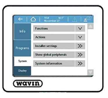
Connection scheme
                                        A          A

                                   A                    A

                             A                                A

                        A                                            A

                  T2
PUMP 1

                       T3
P1

S1       C   S2         Location                                  Location

                            Location                         Location

                                 Location              Location

                                       Location   Location

                                                                             F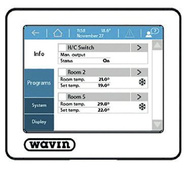
A           A

                                   A                    A

                            A                                 A

                        A                                           A

                  T4
PUMP 2

                       T5
P2

S3       C   S4         Location                                  Location

                            Location                         Location

                                Location               Location

                                       Location   Location

                                                                             G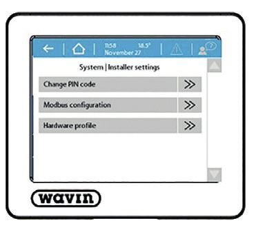
How to connect to the app

    1

    2
                                              SN:123
                                              RK:456

    3        Registration Key (RK) is found on a
             sticker on the CCU; usually on the front.

                                                         +
    4        Press the learn button        on the CCU.

H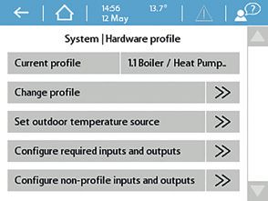
Enroll procedure thermostat & sensors

                                        I
Choose profile
1 2
3 4
System | Installer settings | Hardware profile | Change profile
JComponents
Number* Article code Description
I 3077000 Wired Thermostat
3077001 Wireless Thermostat
3077004 Wireless Thermostat with Infrared Floorsensor
II 3077002 Wired Sensor
3077003 Wireless Sensor
III 4063803 Wallbox Frame for Thermostat or Sensor
IV 4063796 Central Control Unit (CCU), 8 input/16 output, no cable
4063797 Central Control Unit (CCU), 8 input/16 output, F-plug
4063798 Central Control Unit (CCU), 8 input/16 output, G-plug
4064446 Central Control Unit (CCU), 8 input/16 output, K-plug
V 4063800 Extension Unit (EU-A) for Central Control Unit, additionl 8 outputs
VI 4063801 Extension Unit (EU-VFR) for Central Control Unit, 6 Voltage Free Relays
VII 4063802 Commissioning Touch Screen (LCD-200)
VIII 4063806 Wired Outdoor Sensor
4063807 Wireless Outdoor Sensor
IX 4063809 External Antenna (3pin)
X 4063810 Wired Floor Sensor
XI 4064150 Pipe Sensor, strap on
XII 4054937 Actuator 24V NC VA50
XIII 4064828 Sentio Connection Cable for PC (Windows)
XIV 4064829 Servo motor 3-pos., 24V
4030065 Servo motor 10-0V control (Wavin Italy)
XV 4063808 Sentio Outdoor Thermometer
XVI 4063804 Smart Radiator Thermostat, RA
4063805 Smart Radiator Thermostat, M28/30
* See page E
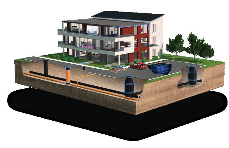
1Ports CCU and EUs
Number* Symbol Description
1 T1 Connection for temperature sensor, Outdoor temperature sensor
2 T2 Connection for temperature sensor, Flow, heating circuit 1
3 T3 Connection for temperature sensor, Return, heating circuit 1
4 T4 Connection for temperature sensor, Flow, heating circuit 2
5 T5 Connection for temperature sensor, Return, heating circuit 2
6 S1/C/S2 Servo motor, heating circuit 1
7 S3/C/S4 Servo motor, heating circuit 2
8 O1/GN Universal programmable input / output 1
9 O2/GN Universal programmable input / output 2
10 +U/A/B/GN ROXi bus
11 AO/GN Analog output 0-10V
12 PO PWM output (To be used with “GN” for analog output )
13 PI PWM input (To be used with “GN” for analog output)
14 VFR 1 Connection to voltage-free relay 1
15 VFR 2 Connection to voltage-free relay 2
16 P1/N/PE Connection to pump relay 1 (230V)
17 P2/N/PE Connection to pump relay 2 (230V)
18 L/N/PE Connection to 230V supply
19 A1 – A8 Actuator outputs 1-8 (for 1 or 2 PC of thermal acutator 24V 1W/PC)
20 - Internal connection between Control Unit(IV) and Extension Unit (V, VI)
21 A9 – A16 Actuator outputs 9-16 (for 1 PC of thermal acutator 24V 1W/PC)
22 A/B Connection to 24V voltage-free relay
23 C Connection to voltage-free relay C, AC 24-230V, 1A each
24 D Connection to voltage-free relay D AC 24-230V, 1A each
25 E Connection to voltage-free relay E AC 24-230V, 1A each
26 F Connection to voltage-free relay F AC 24-230V, 1A each
Installation and connection of the Wavin Sentio Control Unit and Extension Units may only be carried out
by an authorized installer.
* See page B
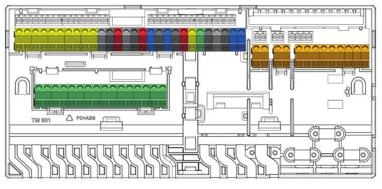
2LEDs and Buttons CCU and EUs
Letter* LED/Button Function Light Meaning
A Status Off No power supply of the unit
Green On Power on – everything ok
Red On Bootloader is working
B Warning Yellow flash Error, e.g. connection to peripheral lost
Yellow slow flash Bootloader is working / preparing for update
Yellow fast flash Update is running
C Cooling Blue On Cooling is active
D LAN status Green On Connection to LAN and cloud service
Green flash Connected to LAN but no cloud service
Green fast flash Learn mode active for registrating unit to the app
Blue On Auto update has found a new version and is ready to update
Blue flash Auto update is ready to check for a new version
Blue fast flash Auto update is checking a new version
E Peripherals enrolling Green On Global peripherals enrolled
Red flash Enrolling mode (global peripherals can be connected)
F Channel Selection - Select a channel by moving it to the left
G 1 – 16 Actuator channels Red On Heating
Green On Idle – no heating / no cooling
Blue On Cooling
Purple On Idle – Room without thermal actuator; e.g. room with
Smart Radiator Thermostat
Cyan On Idle – Output used for special purposes E.g. External Actuator
Red flash Enroling mode (peripherals can be connected)
Red fast flash Output overloaded, heating demand
Green flash Missing periphery
Green fast flash Output overloaded, idle, no demand
Blue fast flash Output overloaded, cooling demand
Green/red Heating blocked
Green/blue Cooling is blocked
Purple/red Heating is blocked for room without thermal actuator
White slow flash Periodic activation (preventive maintenance)
White On First time opening of thermal actuators
Yellow Changing profile settings / restart / updating peripheral
H Enter Confirm action, Learn mode to connect to the APP,
Reset a channel (hold 10s), Factory Reset (hold 20s)
K Channel Selection Select a channel by moving it to the right
O A–F VFR channels Green On VFR set and ready
Red on VFR active
* See page A
3Connect
Mounting the Control Unit
Mount the Central Control Unit (IV) and if required the Extension Unit(s) (V, VI) on the wall with the screws provided. If you want
to mount them side by side, they can be connected by the provided connection element.
Electrical connection for Control Unit (CCU) and extension Unit(s) (EU)
If the CCU and the EU are mounted side by side, the two units are electrically connected using the supplied cable and connect
it to port no. 20. If the CCU / EU are located further away from each other, they are electrically connected via the ROXi bus
(port 10).
Cable Type Diameter / Square Resistance (Ω/km) No. of Actuators Max. cable length
(live wired) at the EU between CCU and EU
CC – 01 0,8 mm/0,52 mm2 38 4 30 m
8 15 m
Copper Cable 1,1 mm/1,0 mm2 18 4 70 m
8 30 m
Connecting the actuators If wired room thermostats/sensors are used, connect the
Bus-cable at the terminals “U+, A, B and GND” (port 10).
Max. 16 actuators (XII) can be added to a Sentio system, in The room thermostats/sensors are connected to the CCU
doing so max. two actuators can be connected to each port by a 2x2 wired, unshielded, twisted pair cable (2x2x24
at the CCU and one per output on the EU. AWG).
Mount the actuators (XII) on the manifold. Closing the CCU and EUs
1. Screw the grey valve adapter in the manifold by hand Before closing the CCU/EU ensure that all wires have been
2. Press the actuator with you hand until you hear a “click” routed through the wiring channels at the bottom of the
units. If the CCU and EU are connected, a part on the front
The actuators are connected with the ports 19 (CCU) or 21 of the CCU and EU must be removed, leaving space for the
(EU), see page B. cable between the two units. The front of the CCU/EU is
pressed into place on the base plate and the locking pin (N)
Mounting the room thermostats/sensors is pushed upwards till you hear a “click”.
Mount the Thermostat (I)/Sensors (II) on a dry place in the
particular dry, indoor room. It is recommended to choose a
place approx. 1,5m above the floor without draught, stag-
nant air and radiant heat (from sun or electrical devices),
not on an exterior wall or near windows. Do not install them
closed to metal parts or other objects that may interfere with
the radio signals.
4Connecting to LAN the pre-set sub-profiles as shown in the table below to
enroll all units at once. Wavin can offer dehumidifier units
If you want to be able to control the system via the Sentio P300, S300, and dehumidifier units with heating/cooling
App, the CCU must be connected to your router. This is coil PC300 and SC300 for this functionality. For more
done with a standard netcable (RJ45 plug), which is con- information on dehumidifier see the Technical Handbook at
nected to port M at the bottom of the CCU. www.wavin.com/Sentio.
Connecting the Commissioning Touch Screen Limitations
To get a complete overview of the whole installation and The Sentio system can contain a fixed maximum number of
be able to set up all parameters for the system a commis- components. Keep these in mind when designing a system.
sioning touch screen can be connected. It is connected
with a standard netcable (RJ-45 plug) into port J or L at Max
the CCU/EU.
Rooms 24
Connecting a Smart Radiator Thermostat Thermo Actuators 24V DC 1W 16
Dehumidifiers 4
After attaching the M28, M30 or RA adapter on the ther- Room Thermostats/Sensors 24
mostatic valve the Radiator Thermostat(XVI) can be clicked Outdoor Temperature Sensor 1
on. To enroll this component, select a room channel on the Smart Radiator Thermostat 16
CCU and insert the batteries or use the commissioning tool. Extension Unit (EU-A) 2
If the Radiator Thermostat (XVI) is in a position where it is Extension Unit with VFR (EU-VFR) 2
not properly able to measure the room temperature, add Touch Screen Commissioning tool 2
a room Thermostat(I)/Sensor(II) to improve temperature
measurements.
Connecting a Dehumidifier unit
For humidity control and optimized cooling a dehumidifier
can be added to the system via an Extension Unit with
relays (VI). By connecting the dehumidifier connection (“D”)
and the thermal integration connection (“TI”) according to
Pre-set Unit Connections to Extension Unit (EU-VFR)
A B C D E F
1.1 1 x Dehumidifier (P/S300) D
1.2 2 x Dehumidifier (P/S300) D D
1.3 3 x Dehumidifier (P/S300) D D D
1.4 4 x Dehumidifier (P/S300) D D D D
2.1 1 x Dehumidifier with H/C coil (PC/SC300) D TI
2.2 2 x Dehumidifier with H/C coil (PC/SC300) D TI D TI
2.3 3 x Dehumidifier with H/C coil (PC/SC300) D TI D TI D TI
5Set
During the start-up of the Sentio system you have to choose the type of system (profile) that the Sentio unit has to control.
To make this manual easier to read to most common types are included. All other descriptions you can find at www.wavin.
com/Sentio
By default the Sentio Unit comes with profile 1.1 as active. To change the profile and/or set all parameters a Sentio
commissioning touch screen (VII) or the PC-tool (download via www.wavin.com/Sentio , Sentio Connection Cable for
PC (XIII) required) is needed.
Choose Profile
Commissioning Touch Screen: System | Installer settings | Hardware profile | Change profile*
Heating/cooling source With Profile Required
District heating None 1.0
1 ITC loop 1.3.1 Inlet sensor, outlet sensor
2 ITC loops 1.3.2 Inlet sensor, outlet sensor
Boiler/Heat pump None (On/off control) 1.1
0-10V control 1.2
Condensing boiler 0-10V control, 1 ITC loop 2.2.1 Inlet sensor, outlet sensor
0-10V control, 2 ITC loop 2.2.2 Inlet sensor, outlet sensor
Heat pump UFH/UFC Heat/Cooling switch 3.3.0 Inlet sensor (recommended)
Automatic switch 3.3.1 Outdoor Sensor, Inlet sensor (recommended)
1 ITC + Heat/Cooling switch 3.3.2 Inlet sensor, outlet sensor
1 ITC + Automatic switch 3.3.3 Outdoor Sensor, Inlet sensor, outlet sensor
Any single source 2 Heat/cooling circuits 4.1.1
+ dehumidifier 1 ITC 4.1.2 Inlet sensor, outlet sensor
1 ITC + heat/cooling circuit 4.1.3 Inlet sensor, outlet sensor
2 ITC + heat/cooling circuit 4.1.4 Inlet sensor, outlet sensor
* see page J
If more than 8 outputs are required, then an extension unit (EU-A) (V) can be added to the system.
Most situations are covered by selecting the right profile, but some settings might have to be set for your specific system:
When using a wired thermometer (XV) on input T1 make sure to enable this sensor.
Commissioning Touch Screen: System | Installer settings | Hardware profile | Set outdoor temperature source
Rooms are default controlling on air temperature, for UFH with floor sensors set regulation mode to floor
(or ‘air & floor’).
Commissioning Touch Screen: Room | Settings | Winter mode | Advanced Settings | Regulation mode
ITC-servo type is by default a 3-points servo motor, for a different type see Technical Handbook.
Commissioning Touch Screen: System | Installer settings | Hardware profile | Configure required inputs and output |
Servos | ITC Servo | Servo type
To change a room name go to Info | Room | Settings
6Global peripherals
Global peripherals, as Extension Units (V, VI), Outdoor Sensor (VIII) and Commissioning Touch Screen (VII), collect and display
values that are used to control the entire Sentio system or are used to extend the Sentio system.
The global components have to be registered to the CCU. Usually they are automatically enrolled and registered at the
system startup. The only global component that is not automatically registered is the Wireless Outdoor Temperature Sensor.
It is registered following this way:
1. Press button F the CCU (IV) as long till the LED E is flashing red.
2. Insert the battery(s) into the outdoor temperature sensor. The LED E on the CCU now will glow green.
Local peripherals
Local peripherals, as room thermostats and room sensors, collect and display values for the room they are mounted in.
A total of 24 Local peripherals can be registered to one CCU.
Before the system can be used all local peripherals have to be registered to the channel(s) they have to control.
They are registered in the following way:
1. Press button F or K on the CCU (IV) until the LED next to the channel you want to register the thermostat/sensor
to is flashing red.
2. a) Wireless peripherals: Insert the batteries into the room thermostat / sensor (see manual added to the package)
b) Wired peripherals: Touch the room thermostat / sensor touch area and hold it for approx. 5 sec
(see manual added to the package).
When the CCU has received the enrollment code from the room thermostat / sensor the light next to the channel you
choose will switch to continuous on.
3. If more than one channel has to be registered to the same room thermostat / sensor, repeat step 1 and 2
Repeat the above for the other room thermostats / sensors to be registered.
If you have to remove a local peripheral from the system follow this steps:
1. Press button F or K on the CCU (IV) or Extension Unit (V, VI) until the desired channel flashes red.
2. Hold button H on the CCU (IV) or Extension Unit (V, VI). The LED next to the relevant channel turnes off.
Actuators
The actuators are supplied open and will not close until they have been activated for 10 minutes. If an output has not been
activated within two hours after starting the CCU, it will automatically activate the channel to close the actuator.
In total max. 16 acutators can be connected to a CCU/EU combination!
7GO
When using zone-control in residential applications each Thermostat
zone can be controlled via the thermostat in that particular
room. An alternative is to control each room from a distan- To control a room`s settings via the thermostat is shown in
ce (so no need to be present in the room) via the Wavin the manual that is added to each thermostat`s box.
Sentio app.
Wavin Sentio app
To control a room`s settings via the app, go to the Google
Play or iOS App Store and download the Sentio app. After
the registration process the app is ready for use. A QR-code
to the app stores and a short explaniation is also shown on
page H in this Quick Guide.
It is mandatory that the CCU is connected via the LAN port
to the internet and that the connection is stable.
8Komponenter
Nummer* Artikel kode Beskrivelse
I 3077000 Fortrådet rumtermostat
3077001 Trådløs rumtermostat
3077004 Trådløs rumtermostat med IR gulvsensor
II 3077002 Fortrådet rumtermostat
3077003 Trådløs rumtermostat
III 4063803 Ramme til rumtermostat/-sensor
IV 4063796 Styreenhed, 8 zoner, ingen netkabel
4063797 Styreenhed, 8 zoner, netkabel med F stik (EU)
4063798 Styreenhed, 8 zoner, netkabel med G stik (UK)
4064446 Styreenhed, 8 zoner, netkabel med K stik (DK)
V 4063800 Udvidelsesmodul til Sentio styreenhed, 8 udgange
VI 4063801 Udvidelsesmodul til Sentio styreenhed, 6 potentiale frie relæer
VII 4063802 Display
VIII 4063806 Fortrådet udendørstemperatursensor
4063807 Trådløs udendørstemperatursensor
IX 4063809 Ekstern antenne
X 4063810 Fortrådet gulvsensor
XI 4064150 Anlægsføler, “Strap on”
XII 4054937 Telestat 24V NC VA50
XIII 4064828 Forbindelseskabel PC (Windows)
XIV 4064829 Servo motor 3-punkt, 24V
4030065 Servo motor, 10-0 V
XV 4063808 Udendørstemperaturføler
XVI 4063804 Radiator Termostat, trådløs, RA
4063805 Radiator Termostat, trådløs, M28/30
* Se side E
9Tilslutninger Sentio styreenhed og
udvidelsesmodul
Nummer* Symbol Beskrivelse
1 T1 Tilslutning af temperatursensor, Udendørstemperaturføler
2 T2 Tilslutning af temperatursensor, fremløb, varmekreds 1
3 T3 Tilslutning af temperatursensor, retur, varmekreds 1
4 T4 Tilslutning af temperatursensor, fremløb, varmekreds 2
5 T5 Tilslutning af temperatursensor, retur, varmekreds 2
6 S1/C/S2 Servo motor, varmekreds 1
7 S3/C/S4 Servo motor, varmekreds 2
8 O1/GN Universel programmerbar indgang/udgang 1
9 O2/GN Universel programmerbar indgang/udgang 2
10 +U/A/B/GN ROXi bus
11 AO/GN Analog udgang 0-10V
12 PO PWM udgang (anvendes med “GN” til analog udgang)
13 PI PWM indgang (anvendes med “GN” til analog udgang)
14 VFR 1 Tilslutning til spændingsfrit relæ 1
15 VFR 2 Tilslutning til spændingsfrit relæ 2
16 P1/N/PE Tilslutning til pumpe relæ 1 (230V)
17 P2/N/PE Tilslutning til pumpe relæ 2 (230V)
18 L/N/PE Tilslutning til 230V forsyning
19 A1 – A8 Telestat udgang 1-8 (for 1 eller 2 stk. telestat/er 24V 1W/stk.)
20 - Intern tilslutning mellem styreenhed (IV) og udvidelsesmodul (V, VI)
21 A9 – A16 Telestat udgang 9-16 (for telestat 24V 1W)
22 A/B Tilslutning til pontentiale fri relæer A/B, Maks. 24V
23 C Tilslutning til potentiale fri relæ C, Maks. 230V
24 D Tilslutning til potentiale fri relæ D, Maks 230V
25 E Tilslutning til potentiale fri relæ E, Maks. 230V
26 F Tilslutning til potentiale fri relæ F, Maks. 230V
Installation og tilslutning af Wavin Sentio styreenhed og udvidelsesmodul må kun udføres af en autoriseret installatør.
* Se side B
10LEDs og knapper på Sentio styreenhed og
udvidelsesmodul
Bogstav* LED/Knap Funktion Lys Betydning
A Statur FRA Ingen strømforsyning
Grøn TIL Tilsluttet -Alt OK
Rød TIL Bootloader arbejder
B Advarsel Gul blinker Fejl, ex. Mistet forbindelse til enhed
Gul blinker langsomt Bootloader arbejder / forbereder opdatering
Gul blinker hurtigt Updatering igang
C Køl Blå TIL Køl er aktiv
D LAN Status Grøn TIL Forbindelse til LAN og cloud service
Grøn blinker Forbindelse til LAN og ingen cloud service
Grøn blinker hurtigt Lærings mode aktiv for registrering af enhed til Sentio App
Blå TIL Auto opdatering er klar til at opdatere systemet
Blå blinker Auto opdatering er klar til at tjekke for ny verison
Blå blinker hurtigt Auto opdatering tjekker for ny verison
E Globalt komponenter, Grøn TIL Globale komponenter tilmeldt
status Rød blinker Tilmeldingsmode (globale komponenter kan tilmeldes)
F Kanal vælger - Trykknap til at flytte en kanal til venstre
G 1 – 16 Telestater, status Rød TIL Varme
Grøn TIL Stand by -ingen varme/køl
Blå TIL Køl
Lilla TIL Ikke aktiv - rum uden tilsluttet telestat; f.eks. rum med radiatortemostat.
Cyan TIL Ikke aktiv - Udgang anvendt til speciel formål. F.eks. telestat på
affugter med varme- /køleveksler
Rød blinker Tilmeldingsmode (lokale komponenter kan tilmeldes)
Rød blinker hurtigt Overbelastet udgang, varme kald
Grøn blinker Mistet forbindelse til komponent
Grøn blinker hurtigt Overbelastet udgang, stand by, intet behov
Blå blinker hurtigt Overbelastet udgang, køle behov
Grøn/Rød Varme er blokeret, ex. fordi udendørstemperatur er for høj
Grøn/Blå Køl er blokeret, ex. fordi udendørstemperatur er for lav
Lilla/rød Varme er blokeret i rum uden tilsluttet telestat
Hvid langsom blinker Periodisk aktivering (forebyggende vedligehold)
Hvid TIL First- open af telestater
Gul Ændre profilopsætning / genstart / opdaterer komponenter
H Enter Nulstil en kanal (10s), aktiver tilmeldingsmode for
Sentio App (1s), Fabriksgenstart (20s)
K Kanal vælger Trykknap til at flytte en kanal til højre
O A–F Potentiale Grøn TIL Potentiale fri relæ er indstillet, “Åben”
frie relæer Rød TIL Potentiale fri relæ er “Lukket”
* Se side A
11Tilslut
Montering af Sentio styreenhed
Monter Sentio styreenheden (IV) og hvis påkrævet Sentio udvidelsesmodul(er) (V,VI) på væggen med de medfølgende skruer.
Udvidelsesmoduler kan monteres på siden med det medfølgende beslag.
Elektrisk tilslutning af Sentio styreenhed og Sentio udvidelsesmoduler
Hvis Sentio styreenheden og udvidelsesmodulet monteres i forlængelse skal de sammenkobles med det medfølgende kabel
til port 20 i Sentio styreenheden og udvidelsesmodul. Hvis enhederne ikke monteres ved siden af hinanden skal de kobles
sammen via ROXi bus (port 10)
Kabel type Diameter / kvadrat Modstand (Ω/km) Antal telestater i Max kabellængde mellem
udvidelsesmodulet Sentio styreenhed og Sentio
udvidelsesmoduler
CC – 01 0,8 mm/0,52 mm2 38 4 30 m
8 15 m
Kobber kabel 1,1 mm/1,0 mm2 18 4 70 m
8 30 m
Tilslutning af telestater Hvis en fortrådet rumtermostat/ - sensor bruges tilslut BUS-
kablet med terminal “U+, A, B og GND” (port 10). Tilslut
Maks. 16 telestater (XII) kan tilføjes Sentio systemet. termostat/sensor til Sentio styreenheden med et 2x2 kabel,
Maks. 2 telestater per udgang styreenheden. uskærmet, snoede par (2x2x24 AWG).
Maks. 1 telestat per udgang i udvidelsesmodulet.
Lukning af Sentio styreenhed og
Monter telestaterne (XII) på fordelerrøret. Sentio udvidelsesmoduler
1. Skru ventil adaptoren på fordelerrøret med hånden. Før lukning af Sentio styreenhed og Sentio udvidelses-
2. “Klik” telestaten på adaptoren. moduler sikres at alle kabler er ført gennem kanalerne i
bunden af enheden. Hvis Sentio styreenhed og Sentio
Telestater tilsluttes udgang 19 (Sentio styreenhed) eller 21 udvidelsesmoduler er forbundet skal en del af frontpladen
(Sentio udvidelsesmodul), se side B. på Sentio styreenhed og Sentio udvidelsesmodulet fjernes
for at give plads til kablet mellem de to enheder. Pres fron-
Montering af rumtermostat/-sensor ten på plads i basen og fikser med låsepindene (N) indtil
de giver et “klik”.
Monter rumtermostat (I)-sensor (II) et tørt sted i rummet.
Det anbefales at vælge en placering 1,5m over gulvet uden
træk, stillestående luft eller strålevarme fra eksempelvis sol
eller elektriske komponenter, Ikke på en ydervæg eller tæt
på et vindue. Monter ikke rumtermostaten/-sensoren tæt på
metaldele da dette kan forstyrre radiosignalet.
12Tilslutning til LAN integrations del (“TI”) som vist i nedenstående tabel, kan
alle enheder, via de forudindstillede underprofiler, indstilles
For at kunne regulere systemet via Sentio App skal Sentio på én gang. Wavin sælger affugtere type P300, S300, og
styreenheden tilsluttes en router. Dette gøres med et affugtere med varme-/køleveksler type PC300 og SC300*.
standard netkabel (RJ45), som tilsluttes port M i bunden af For mere information vedrørende tilslutning af affugtere, se
Sentio styreenheden venligt Teknisk Håndbog på www.wavin.dk/sentio.
Tilslutning af Sentio display Begrænsninger
For et komplet overblik over installationen og for at ændre Der kan tilsluttes et fast antal komponenter til et Sentio-
alle parametre i systemet kræves tilslutning af et Sentio system. Se venligst nedenstående tabel.
display. Dette gøres med et standard netkabel (RJ45), som
tilsluttes port J eller L i bunden af Sentio styreenheden. Maks.
Tilslutning af radiatortermostat Rum 24
Telestater 24V DC 1W 16 16
Efter monteringen af M28, M30 eller RA adapteren på Affugtere 4
termostatventilen, kan radiatortermostaten(XVI) klikkes på Rumtermostater/-sensorer 24
adapteren. Tilmeld radiatortemostaten ved at vælge det Udendørstemperaturføler 1
ønskede rum/kanal på styreenheden og indsæt batterierne Radiatortermostat 16
eller anvend Sentio Displayet. Hvis radiatortemostaten Udvidelsesmodul f/telestater (EU-A) 2
monteres så den påvirkes af omgivelserne, således at den Udvidelsesmodul med potentiale frie
indbyggede temperatursensor ikke kan måle den korrekte relæer (EU-VFR) 2
rumtemperaturen, er det muligt at tilføje en rumtermos- Sentio Display 2
tat/-sensor til samme rum som radiatortermostaten.
Tilslutning af en affugter
For styring af fugtigheden i rummene og optimeret køling
kan systemet udvides med en eller flere affugtere. De tilslut-
tes ved at tilføje et udvidelsesmodul m/potientale frie relæer
(VI). Ved at tilslutte affugterdelen (“D”) og den termiske
Underprofiler Enhed Tilslutning i udvidelsesmodul (EU-VFR)
A B C D E F
1.1 1 x Affugter (P/S300) D
1.2 2 x Affugter (P/S300) D D
1.3 3 x Affugter (P/S300) D D D
1.4 4 x Affugter (P/S300) D D D D
2.1 1 x Affugter med varme- /køleveksler (PC/SC300) D TI
2.2 2 x Affugter med varme- /køleveksler (PC/SC300) D TI D TI
2.3 3 x Affugter med varme- /køleveksler (PC/SC300) D TI D TI D TI
13Setup
Ved opstart af Sentio systemet skal der vælges et system (profil) som Sentio enheden skal regulere. Herunder findes en
oversigt over de mest almindelige profiler. Øvrige profiler kan findes på www.wavin.dk/sentio.
Som standard kommer Sentio styreenheden med profil 1.1 aktiv. For at ændre profilen og / eller indstille alle parametre skal
der anvendes et Sentio display (VII) eller PC-værktøjet (Kan downloades på www.wavin.dk/Sentio). For at kunne anvende
PC-værktøjet skal Sentio tilslutningskabel til PC (XIII) anvendes.
Vælg profil
Sentio Display: System | Installatørindstillinger | Hardware profil | Ændre profil*
Varmekilde Med Profil Påkrævet tilbehør
Fjernvarme Ingen 1.0
1 kreds vejrkompensering (ITC) 1.3.1 Udendørstemperaturføler, Fremløbsføler, Returføler
2 kreds vejrkompensering (ITC) 1.3.2 Udendørstemperaturføler, Fremløbsføler, Returføler
Kedel/varmepumpe Ingen (ON/OFF regulering 1.1
0-10V regulering 1.2
Kondenserendekedel 0-10V regulering, 1 kreds
Vejrkompenseing (ITC) 2.2.1 Udendørstemperaturføler, Fremløbsføler, Returføler
0-10V regulering, 2 kreds
Vejrkompenseing (ITC) 2.2.2 Udendørstemperaturføler, Fremløbsføler, Returføler
Varmepumpe Varme/køl manuel omskiftning 3.3.0 Fremløbsføler (Anbefalet)
Gulvarme/-køl Automatisk omskiftning 3.3.1 Udendørstemperaturføler, Fremløbsføler (Anbefalet)
1 kreds vejrkompensering (ITC)
+ Varme/køl manuel omskiftning 3.3.2 Udendørstemperaturføler, Fremløbsføler, Returføler
1 kreds vejrkompensering (ITC)
+ Varme/køl automatisk omskiftning 3.3.3 Udendørstemperaturføler, Fremløbsføler, returføler
Varmepumpe + affugter/e 2 varme-/kølekredsen 4.1.1
1 ITC 4.1.2 Udendørstemperaturføler, Fremløbsføler, Returføler
1 ITC + 1 varme-/kølekredsen 4.1.3 Udendørstemperaturføler, Fremløbsføler, Returføler
2 ITC + 1 varme-/kølekredsen 4.1.4 Udendørstemperaturføler, Fremløbsføler, Returføler
* Se side J
Hvis der kræves mere end 8 udgange tilføjes et Sentio udvidelsesmodul.
Ved at vælge den rette profil er de fleste indstillinger for systemet allerede lavet. Enkelte indstillinger skal dog tilpasses de
enkelte installation. Se nedenstående afsnit:
Hvis du anvender en udendørstemperaturføler tilsluttet til T1, skal den aktiveres inden den kan anvendes.
Sentio display: System | Installatørindstillinger | Hardware profil | Vælg udendørstemperaturføler
Rum er som standard sat op til luft temperaturregulering. For gulvarme med gulvføler sæt regulering til “gulv”
eller luft & gulv.
Sentio display: Rum | Indstillinger | Avancerede indstillinger | Regulerings mode |
ITC-servo type er som standard sat til 3-punkts servo. For andre typer se manual.
Sentio display: System | Installatørindstillinger | Hardware profil | Konfigurer påkrævede indgange og udgange |
Servomotore | ITC servo
Ændre rum navne Rum | Indstillinger | Navn
14Globale komponenter
Globale komponenter, som udvidelsesmoduler (V, VI) opsamler og viser værdier, der anvendes til styring af hele systemet eller
anvendes til udvidelse af systemet.
De fleste globale komponenter i dit Sentio system vil ved opstart automatisk blive tilmeldt systemet. Sentio trådløs
udendørstemperatursensor skal dog altid tilmeldes manuelt til dit Sentio system. Hvis der i systemet er tilsluttet mere end
et udviddelses modul af samme slags, skal det ene af udvidelsesmodulerne tilmeldes manuelt. Det andet udvidelsesmodul
tilmeldes automatisk. Udendørstemperatursensoren tilmeldes på følgende måde:
1. Tryk på knap F på Sentio styreenhed (IV) indtil LED E blinker rødt
2. Isæt batteri(er) på udendørstemperaturføleren. LED E vil nu lyse grønt på styreenheden
Udvidelsesmodulet tilmeldes på følgende måde:
1. Tryk på knap F på Sentio styreenhed (IV) indtil LED E blinker rødt
2. Tryk på “Enter” knappen på det udvidelsesmodul du ønsker at tilmelde.
3. Vent ca. 10 sekunder til den gule lysdiode på udvidelsesmodulet slukker, og LED E på styreenheden vil nu lyse grønt.
Lokale komponenter
Lokale komponenter, som rumtermostater/-sensorer opsamler og viser værdier, der anvendes i det rum, de er monteret.
Maksimalt 24 komponenter kan registreres på en styreenhed.
Før systemet kan tages i brug skal hver af rumtermostaterne/-sensorne tilmeldes til den/de kanaler, som de skal
styre. De tilmeldes på følgende måde:
1. Tryk knap F eller K på Sentio Styreenheden/Udvidelsesmodulet indtil lysdioden ud for den kanal som rumtermostaten/
rumsensoren skal tilmeldes til blinker rødt.
2.a Ved trådløse Rumtermostater/- sensorer:
Sæt batterierne i rumtermostaten/- sensoren (se monteringsvejledning for rumtermostater/- sensorer).
2.b Ved fortrådede rumtermostater/- sensorer:
Tryk på rumtermostatens/- sensors Touch område og hold den i ca. 5 sek. (se monteringsvejledning
for rumtermostater/- sensorer).
Når Sentio Styreenheden har modtaget tilmeldingskoden fra rumtermostaten/rumsensoren, skifter lyset ud for den
pågældende kanal til fast grønt/rødt lys.
3. Skal rumtermostaten/- sensoren tilmeldes mere end én kanal, gentages punkt 1 og 2 for den næste kanal.
Gentag ovenstående for de øvrige rumtermostater/-sensorer, der skal indkodes.
15Start
Sletning af lokale komponenter Ved brug af zone-regulering i beboelse kan hver zone
reguleres via rumtermostaten i det enkelte rum. Alternativt
Ønsker du at afmelde en lokal komponent fra Sentio kan de enkelte rum fjernreguleres via Sentio App.
Styreenheden/Udvidelsesmodulet følges nedenstående
(Bemærk! Alle tilmeldte komponenter på den valgte kanal Rumtermostat
bliver afmeldt):
For rumindstilling via rumtermostat se medfølgende manual.
1. Tryk på knap F eller K på Sentio Styreenheden/
Udvidelsesmodulet indtil lysdioden udfor den kanal Sentio App
som skal slettes blinker rødt.
2. Tryk på knap H på Sentio Styreenheden/ For rumindstilling via Sentio App, gå til Google Play eller
Udvidelsesmodulet iOS App Store og download Sentio App. Efter registrering
Lysdioden ud for den pågældende kanal/zone slukker. er Appen klar til brug. En QR kode til App store og en kort
forklaring findes på side H i denne quick guide.
Telestater
Det er nødvendigt at styreenheden er tilsluttet via LAN
Telestaterne leveres med First Open-funktion. porten til internettet og at forbindelsen er stabil.
Styreenheden har en indbygget en funktion der ved
opstart automatisk starter aktiverer de udgange som der er
monteret en telestat på. Efter denne opstart er telestaten
er klar til drift.
Der kan maks. tilkoble 16 telestater til et Sentio
system.
16Composants
Numéro* Code article Description
I 3077000 Thermostat filaire
3077001 Thermostat sans fil
3077004 Thermostat sans fil avec capteur
II 3077002 Sonde température/humidité filaire
3077003 Sonde température/humidité sans fil
III 4063803 Support mural pour thermostat ou sonde
IV 4063796 U centrale 8ent/16 sort ss cable
4063797 U centrale 8ent/16 sort prise F
4063798 U centrale 8ent/16 sort prise G
4064446 U centrale 8ent/16 sort prise K
V 4063800 U ext 8 entres/16 sorties
VI 4063801 Unité d’extension 6 relais
VII 4063802 Ecran tactile de configuration
VIII 4063806 Sonde externe filaire
4063807 Sonde externe sans fil
IX 4063809 Antenne externe
X 4063810 Capteur sol filaire
XI 4064150 Capteur tube
XII 4054937 Moteur thermique 24V NC VA50
XIII 4064828 Cable connexion PC
XIV 4064829 Servomoteur 3 positions 24V
4030065 Servomoteur contrôle 10-0V
XV 4063808 Thermomètre extérieur
XVI 4063804 Thermostat Radiateur Smart, RA
4063805 Thermostat Radiateur Smart, M28/30
* Voir page E
17Ports UCC et UE
Numéro* Symbole Description
1 T1 Connexion pour capteur température, Sonde température extérieure
2 T2 Connexion pour capteur température, Départ, Circuit 1
3 T3 Connexion pour capteur température, Retour, Circuit 1
4 T4 Connexion pour capteur température, Départ, Circuit 2
5 T5 Connexion pour capteur température, Retour, Circuit 2
6 S1/C/S2 Servomoteur, Circuit 1
7 S3/C/S4 Servomoteur, Circuit 2
8 O1/GN Entrée / Sortie universelle programmable 1
9 O2/GN Entrée / Sortie universelle programmable 2
10 +U/A/B/GN ROXi bus
11 AO/GN Sortie analogique 0-10V
12 PO Sortie MLI (a utiliser avec GN pour sortie analogique)
13 PI Entrée MLI (a utiliser avec GN pour sortie analogique)
14 VFR 1 Connexion contacteur 1
15 VFR 2 Connexion contacteur 2
16 P1/N/PE Connexion relais pompe 1 (230V)
17 P2/N/PE Connexion relais pompe 2 (230V)
18 L/N/PE Connexion alimentation 230V
19 A1 – A8 Sorties moteurs thermiques 1-8 (Pour 1 à 2 moteurs 24V 1W/PC
20 - Connexion interne entre UCC (IV) et UE (V, VI)
21 A9 – A16 Sorties moteurs thermiques 9-16 (Pour 1 à 2 moteurs 24V 1W/PC)
22 A/B Connexion contacteur 24V
23 C Connexion contacteur C, AC 24-230V, 1A chacun
24 D Connexion contacteur D, AC 24-230V, 1A chacun
25 E Connexion contacteur E, AC 24-230V, 1A chacun
26 F Connexion contacteur F, AC 24-230V, 1A chacun
L’installation et la connextion de l’Unité de Contrôle Centrale Sentio et des Unité d’Extension doivent être réalisé
par le personnel autorisé compétant.
* Voir page B
18LEDs et Bouttons UCC et UE
Lettre* LED/Boutton Fonction Témoin lumineux Signification
A Etat Eteinte Défaut d’alimentation principale
Verte fixe En fonctionnement - Etat OK
Rouge fixe Bootloader en fonctionnement
B Alarme Jaune clignotante Erreur, ex : connexion périphérique perdue
Jaune clignotante lente Bootloader en fonctionnement / préparation de mise à jour
Jaune clignotante rapide Mise à jour en cours
C Rafraîchissement Bleue fixe Rafraîchissement activé
D Etat LAN Verte fixe Connexion LAN et cloud OK
Verte clignotante Connexion LAN OK, pas de service cloud
Verte clignotante rapide Mode association activé pour enregistrement de l’unité sur l’app
Bleue fixe Nouvelle mise à jour disponible et prête à être appliquée
Bleue clignotante Mise à jour automatique prête à rechercher nouvelle version
Bleue clignotante rapide Mise à jour automatique recherche nouvelle version
E Association Verte fixe Périphériques généraux associés
périphérique Rouge clignotante Mode association (les périphériques généraux peuvent être connectés)
F Sélection canal - Sélectionner un canal par déplacement à gauche
G 1 – 16 Canaux moteurs Rouge fixe Chauffage
thermiques Verte fixe Veille - pas de chauffage / pas de rafraîchissement
Bleue fixe Rafraîchissement
Violette fixe Veille - Pièce sans moteur thermique
(ex : pièce avec Thermostat Radiateur Smart)
Cyan fixe Veille - Sortie utilisée pour usages spéciaux (ex actioneur externe)
Rouge clignotante Mode association (les périphériques peuvent être connectés)
Rouge clignotante rapide Sortie saturée, demande de chaleur
Verte clignotante Périphérique manquant
Verte clignotante rapide Sortie saturée, veille, pas de demande
Bleue clignotante rapide Sortie saturée, demande de rafraîchissement
Verte/rouge Chauffage bloqué
Verte/bleue Rafraîchissement bloqué
Violet/Rouge Chauffage bloqué pour pièce sans moteur thermique
Blanche clignotante lente Activation périodique (maintenance préventive)
Blanc fixe Première ouverture des moteurs thermiques
Jaune Changement de profil en cours/redémarrage / mise à jour de périphérique
H Entrer Confirmer action, Mode association pour connecter l’App,
Mise à zéro d’un canal (maintenir 10s), Retour paramètres
usine (maintenir 20s)
K Sélection canal Sélectionner un canal par déplacement à droite
O A–F Canaux contacteurs Verte fixe Contacteur configuré et prêt
Rouge fixe Contacteur actif
* Voir page A
19Connecter
Fixer l’unité de contrôle
Fixer l’Unité de Contrôle (IV) et, si nécessaire, l’Unité d’Extension (V, VI) au mur à l’aide de la visserie fournie. En cas de
montage côte-à-côte, elles peuvent être assemblées avec l’élément de connexion fourni.
Connexions électriques pour Unité de Controle (UCC) et Unité d’Extension (UE)
Si l’UCC et l’UE sont fixées côte-à-côte, les deux unités peuvent être connectées électriquement à l’aide du câble fourni
connecté au port no.20. Si les deux unités sont séparées, elles sont connectées électriquement via le ROXi bus (port 10).
Type de cable Diamètre / section Resistance (Ω/km) Nombre de moteur Longueur max de cable
thermique sur l’UE entre UCC et UE
CC – 01 0,8 mm/0,52 mm2 38 4 30 m
8 15 m
Câble cuivre 1,1 mm/1,0 mm2 18 4 70 m
8 30 m
Connexion des moteurs thermiques la pièce et non à proximité des fenêtre. Ne pas les installer
à proximité d’éléments métalliques ou objets qui pourraient
Un maximum de 16 moteurs thermiques (XII) peuvent être interférer avec leur signal radio.
connectés au système Sentio. Un maximum de 2 moteurs
peut être connecté à chaque port de l’UCC ou l’UE. Dans le cas de thermostats / sondes filaires, connecter le
câble Bus sur les terminaux “U+, A, B et GND” (Port 10).
Fixer les moteurs thermiques (XII) sur le collecteur : Les thermostats / sondes sont connectés à l’UCC à l’aide
d’un câble à paire tressées 2x2 non blindé (2x2x24 AWG).
1. Fixer la bague d’adaptation grise au collecteur le cas
échéant Fermer l’UCC et UE(s)
2. Clipser le moteur thermique à la main jusqu’à entrendre
un “clic” Avant de fermer l’UCC/UE, s’assurer que tous les câbes
sont guidés dans les canaux prévus à cet effet sur la face
Les moteurs thermiques sont connectés à l’aide du port 19 inférieure de l’unité. Si l’UCC et l’UE sont connectés, une
(CCU) ou 21 (UE), voir page B. partie de la face de l’UCC et de l’UE doit être retiré afin de
laisser place libre au câble de liaison entre les deux unités.
Fixer les thermostats d’ambiance / sondes La face de l’UCC/UE est clipsée en place sur la base et la
goupille de verrouillage (N) est poussée en position vers le
Placer les thermostats (I) ou sondes (II) dans un endroit sec haut jusqu’à entendre un “clic”.
à l’intérieur de la pièce. Il est recommandé un emplacement
à 1,5m du sol, sans courant d’air ou chaleur radiante (expo-
sition solaire, source de chaleur électrique...), à l’intérieur de
20Connexion réseau Raccordez la connexion deshumidification (“D”) et la con-
nexion d’intégration thermique (“TI”) selon les sous-profils
Afin de piloter le système à l’aide de l’application mobile des pré-réglages définis pour les associer en une seule
Sentio, l’Unité de Contrôle Centrale doit être connectée à fois. Wavin peut fournir des unités de deshumidification
votre routeur Internet. Ce branchement est réalisé à l’aide P300, S300 et unités de deshumidification avec boucle de
d’un câble réseau standard (prise RJ-45) connecté au port chauffage/rafraîchissement PC300 et PS300 pour disposer
M sur la face inférieure de l’UCC de cette fonctionalité. Pour plus d’information sur la deshu-
midification, consultez notre manuel d’utilisation disponible
Connexion de l’écran tactile de configuration sur www.wavin.fr/Sentio.
Afin d’accéder aux paramètrage complet de l’installation, Limites
un écran tactile de configuration peut être connecté. Ce
branchement est réalisé à l’aide d’un câble réseau standard Le système Sentio ne peut comporter qu’un nombre limité
(prise RJ-45) connecté au port J ou L de l’UCC/UE. de composants. Veillez à garder ça à l’esprit lors de la
conception d’une installation.
Connecter un Thermostat Radiateur Smart
Max
Après avoir monté l’adaptateur M28, M30 ou RA sur la
vanne du radiateur, le thermostat de radiateur (XVI) peut être Pièces 24
clipsé en position. Pour associer ce composant, sélection- Moteurs Thermiques 24V DC 1W 16 16
nez un canal sur l’UCC puis insérez les batteriez, ou utilisez Deshumidificateurs 4
l’écran de configuration. Si le thermostat de radiateur se Thermostats / sonde d’ambiance 24
trouve positionné dans une configuration qui ne permet pas Capteur température extérieure 1
une mesure correcte de la température de la pièce, ajoutez Thermostat Radiateur Smart 16
un thermostat (I) ou une sonde (II) d’ambiance pour amélio- Unité d’extension (EU-A) 2
rer la mesure de température. Unité d’extension 6 relais (EU-VFR 2
Ecran tactile de configuration 2
Connecter une unité de deshumidification
Pour le contrôle de l’humidité et l’optimisation du rafraîchis-
sement, un deshumidificateur peut être ajouté au systè-
me à l’aide d’une Unité d’Extension avec relais (VI).
Pré- Unité Connexions à l’unité d’extension (EU-VFR)
réglages A B C D E F
1.1 1 x Deshumidificateur (P/S300) D
1.2 2 x Deshumidificateur (P/S300) D D
1.3 3 x Deshumidificateur (P/S300) D D D
1.4 4 x Deshumidificateur (P/S300) D D D D
2.1 1 x Deshumidificateur avec boucle C/R (PC/SC300) D TI
2.2 2 x Deshumidificateur avec boucle C/R (PC/SC300) D TI D TI
2.3 3 x Deshumidificateur avec boucle C/R (PC/SC300) D TI D TI D TI
21Régler
Durant le démarrage du système Sentio il vous faut sélectionner le type de système (profil) que l’unité doit contrôler.
Seul les profil les plus courant sont inclus dans ce document. Retrouvez l’ensemble des configurations possibles dans
notre guide technique. www.wavin.com/Sentio
Par défaut le profil 1.1 est activé. Pour modifier le profil et/ou l’ensemble des paramètres, un écran de configuration (VII)
ou le logiciel Sentio pour ordinateur (cable USB spécifique (XIII) requis) est nécessaire.
Choisir profil
Ecran de configuration : Système | Réglages installateur | Profil matériel | Modifier profil*
Source de chaleur Avec Profil Requis
Réseau de chauffage Néant 1.0
urbain 1 boucle CTD 1.3.1 Capteur départ, capteur retour
2 boucles CTD 1.3.2 Capteur départ, capteur retour
Chaudière / Pompe à chaleur Néant (contrôle on/off) 1.1
0-10V control 1.2
Chaudière à condensation Contrôle 0-10V, 1 boucle CTD 2.2.1 Capteur départ, capteur retour
Contrôle 0-10V, 2 boucles CTD 2.2.2 Capteur départ, capteur retour
Pompe à chaleur Bascule chauffage /
PCBT/PCRBT rafraîchissement 3.3.0 Capteur départ (recommandé)
Bascule automatique 3.3.1 Sonde extérieure, capteur départ (recommandé)
1 CTD + bascule Chauffage /
Rafraîchissement 3.3.2 Capteur départ, capteur retour
1 CTD + bascule automatique 3.3.3 Sonde extérieure, capteur départ, capteur retour
Toute source unique de 2 circuit chauffage/ rafraîchissement 4.1.1
chaleur avec deshumidificateur 1 CTD 4.1.2 Capteur départ, capteur retour
1 CTD + circuit chauffage/rafraîchissement 4.1.3 Capteur départ, capteur retour
2 CTD + circuit chauffage/rafraîchissement 4.1.4 Capteur départ, capteur retour
* Voir page J
Si plus de 8 sorties sont nécessaires, une unité d’extension (EU-A) (V) peut être ajoutée à l’installation.
La plupart des situations sont couvertes en sélectionnant le profil adéquate mais certains paramètres devront peut-être être
modifiés pour votre installation :
Lors de l’utilisation d’un thermomètre filaire (XV) sur l’entrée T1, veillez à bien activer ce capteur.
Ecran de configuration : Système | Réglages installateur | Profil matériel | Définir source température externe
Par défaut, la régulation se fait sur la température de l’air, Pour les PCBT avec capteur sol, régler le mode de régulation
sur sol (ou sol et air).
Ecran de configuration : Pièces | Réglages | Mode hiver | Réglages avancés | Mode régulation
Le type de servomoteur pour le contrôle CTD est réglé par défaut sur 3-point, voir manuel pour un réglage différent.
Ecran de confugiration : Système | Réglages installateurs | Profil matériel | Configurer entrées et sorties nécessaires |
Servo CTD
Pour modifier le nom d’une pièce aller dans Info | Pièce | Réglages
22Périphériques généraux
Les périphériques généraux, tels que les Unités d’Extension (V, VI), Sonde extérieure (VIII) et Ecran de configuration
(VII), recceuillent et affichent les données nécessaires au fonctionnement du système Sentio ou utilisées pour étendre les
fonctionnalités du système.
Les périphériques généraux doivent être associés à l’unité ce contrôle centrale (UCC). En général, cette associaiton est auto-
matique au démarrage du système. Le seul périphérique généraux qui n’est pas associé automatiquement est la sonde de
temparéture extérieure sans fil. Elle s’associe de la façon suivante :
1. Appuyer sur le bouton F de l’UCC (IV) assez longtemps pour que la LED E clignotte rouge.
2. Insérer les batteries de la sonde extérieure. La LED E de l’UCC doit devenir de couleur verte.
Périphériques locaux
Les périphériques locaux, tels que les thermostats et sondes d’ambiance, collectent et affichent les informations des pièces
dans lesquelles ils sont installés. Un maximum de 24 périphériques locaux peut être enregistré sur une UCC.
Avant toute utilisation du système, tous les périphériques locaux doivent être associés au canal / canaux qu’ils doivent
contrôler. Ils s’associent de la manière suivante :
1. Appuyer sur le bouton F ou K de l’UCC (IV), ou unité d’extension, jusqu’à ce que la LED du canal auquel vous souhaitez
associer le thermostat ou la sonde clignotte rouge.
2. a) Périphériques sans fil : insérer les batteries dans le thermostat ou la sonde (voir manuel fourni dans l’emballage).
b) Périphériques filaires : appuyer sur la zone tactile du thermostat ou de la sonde durant 5 secondes environ
(voir manuel fourni dans l’emballage).
Lorsque l’unité a reçu le code d’association du périphérique, la LED du canal associé cessera de clignotter.
3. Si plus d’un canal doit être associé au même périphérique, répéter les étapes 1 et 2.
Répéter les étapes ci-dessous pour les autres thermostats ou sondes à associer.
Suivre les étapes suivantes si un périphérique local doit être retiré du système :
1. Appuyer sur le bouton F ou K de l’UCC (IV) ou de l’unité d’extension (V, VI) jusqu’à ce que la LED du canal désiré
clignotte rouge.
2. Maintenir le bouton H de l’UCC (IV) ou UE (V, VI). La LED du canal concerné doit s’éteindre.
Moteurs thermiques
Les moteurs thermiques sont fournis ouverts et ne se fermeront pas pleinement sans avoir été activés durant une dizaine de
minutes. Si un canal n’a pas été activé dans les 2 heures après démarrage de l’UCC, il sera automatiquement activé afin de
fermer le moteur thermique associé.
Un maximum de 16 moteurs thermique peut être associé à un ensemble UCC+UE !
23C’est parti !
Dans une application résidentielle avec contrôle pièce Thermostat
par pièce, chaque zone peut être contrôlée à travers le
thermostat présent dans cette pièce. L’alternative est de Pour contrôler les paramètres d’une pièce à l’aide d’un
piloter chaque zone à distance à l’aide de l’application thermostat, se référer au manuel présent dans chaque boîte
mobile Sentio. de thermostat.
App Wavin Sentio
Pour contrôler les paramètres d’une pièce à l’aide de
l’applicaiton mobile, se rendre sur le Google Play Store ou
l’iOS App Store et télécharger l’app Wavin Sentio. Après le
processus d’enregistrement, l’app est prête à l’utilisation.
Un lien direct par QR-Code vers les différents App Store
et une rapide explication sont présentes en page H de ce
guide simplifié.
Il est nécessaire et indispensable que l’UCC soit connectée
par voie filaire (LAN) à l’Internet et que la connexion soit
stable.
24You can also read