A Step-by-Step Project Guide - VexTM Machinations: Project Design and Programming: Justin Petersen
←
→
Page content transcription
If your browser does not render page correctly, please read the page content below
Vex Machinations:
               TM

 A Step-by-Step Project Guide
                     Version 1.0

Project Design and Programming: Justin Petersen
         (except where otherwise noted)
         Compilation: Yolande Petersen
           © Justin Petersen and Yolande Petersen
                            2008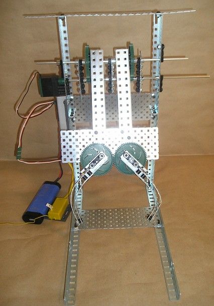
Table of Contents

Preface

Before You Begin

Part 1: VexTM Starter Kit Projects

1.   Squarebot
2.   Flexigearbot
3.   Ping Pong Shooter
4.   Animal Grabber – Part 1: The Gripper
5.   Animal Grabber – Part 2: The Lift

Part 2: Beginning Programming Projects

1.   The Kentucky Do-Nothing
2.   Scaredybot
3.   Edge Detector
4.   Line Follower
5.   Boomerang
6.   Light Seeker

Part 3: Advanced Mechanical Projects

1.   Tricycle Drive
2.   Cup Crusher
3.   Holonomic Drive
4.   Chin-upbot
5.   Candy Sorter

Where to from here?
Preface

        The Vex Robotics Design System was made for creating designs from scratch,
                TM

and experienced robot builders will find themselves in inventors’ heaven. However,
builders without much experience may struggle to put together even a simple robot that
actually works. Step-by-step instructions are given for the Squarebot in the Vex          TM

Inventor’s Guide, but trying to build unique designs beyond that can be an
insurmountable challenge to builders without a foundation in basic mechanics. So far,
few projects with step-by-step instructions are available (two new official projects are
projected to be released by Fall 2008 on the Vex Robotics website). Many ingenious
Vex robot designs are posted on the internet but few of them explicitly tell you which
    TM

parts they use. An eager builder may attempt some of these designs, only to run out of
parts mid-way through the project. After a few false starts, discouragement sets in.
        Having a few projects with instructions can increase a builder’s confidence and
experience until s/he gets a “feel” for how the parts go together. Each project in this
guide demonstrates a different mechanical or programming principle, and together with
Vex for the Technically Challenged, can provide a basic foundation of some important
   TM

engineering principles.
        Part I (Starter Kit Projects) is designed for those who have purchased only the
Starter Kit and would like to build a few fun things without investing more money (yet).
Part II (Beginning Programming Projects) is designed to introduce a variety of sensors
and includes projects that are mechanically simple enough to be built with the Starter Kit.
The programs are also deliberately simple enough to introduce non-programmers to just a
few concepts at a time. Part III (Advanced Mechanical Projects) delves into some deeper
mechanical concepts and uses a variety of parts.
        A note to educators: Students usually prefer to dive in and build a gadget that
does something funky, rather than being blasted with theory. However, these projects
were selected and arranged around something vaguely resembling a curriculum, with an
aim to introduce important engineering concepts in an underhanded way. If all the
projects in this manual are completed, the students will have used many of the sensors
and important mechanical parts that were available as of this writing. More importantly,
they will hopefully emerge with a reasonable grasp of important mechanical and
programming principles that will move them in the direction of being able to design and
construct their own projects.
        We would like to thank our teammates from Team Metal Gear (Alexa Adams,
Nathan Anthony, Eric Flores, Rafi Mitri, Alan Schambers, and Ryan Schambers), for
their participation in the earlier version of this project, and also for making our robotics
experience a fun and wild ride. Most of all, we would like to thank the Great Inventor for
carrying us on this incredible journey.

                                             Justin Petersen, Mechanical Guy
                                             Yolande Petersen, Team Mom & Coach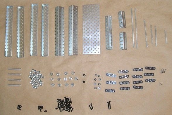
Before You Begin

        Nearly all of the projects in this guide require cutting of the metal pieces that
come in the kit. In many cases, the cut pieces are more useful than the full-length pieces:
having a 5-inch angle bar and a 10-inch angle bar is usually more beneficial than having a
15-inch angle bar, and having two 6-inch square bars is generally preferable to having a
single 12-inch square bar. However, one important thing to consider is that while a large
piece can be made into several small pieces, it is usually not possible to fuse several
small pieces to create a larger one. Also consider that there are a number of possible
cutting configurations for each piece—what if the 12-inch square bar was not needed in
the form of two 6-inch square bars, but three 4-inch square bars instead?
        If you plan to build a large collection of Vex parts, you should be able to cut what
you need without leaving yourself in a hole. However, if your resources are limited and
you feel squeamish about cutting your brand new Vex parts, fret not. In many cases, the
projects in this guide can be built using larger versions of other parts. For example, a 15-
inch angle bar may be substituted for a 10-inch angle bar, simply leaving 5-inches of
extraneous material hanging off. This is not feasible in all situations—sometimes the
extra hanging off could interfere with a moving part of the robot, and replacing a 5-inch
angle bar with a 15-inch leaves such a large portion of metal hanging out that its weight
may hinder the robot's balance. However, if you find yourself with a long bar strip or
plate that is a few holes too large, or an a square bar that is a little bit too long, you can
usually get away with using it and not trimming off the excess length. See this excerpt
from the Animal Grabber building instructions for an example of when it's okay to have a
piece of metal that is slightly too long:

Although the strip in the middle is the ideal length (six holes), the seven-hole strips still
adequately perform the function of holding the two bearing flats.
       The microcontroller has 3 "strips" of ports: motor (with 8 slots), analog/digital
(16 numbered slots, plus RX & TX slots), and interrupt (6 slots). The analog/digital strip
is used for analog inputs, digital inputs, and digital outputs. We reference these ports
throughout the guide. For example "digital input 6" means slot #6 on the analog/digital
strip.
       In Part II of the guide, many projects call for the use of a Squarebot or
Flexigearbot. However, in most cases these specific models are recommend simply on
the basis of ease of mounting. If you have a similar robot on which you can mount the
"peripherals" added for sensor use, you are free to use that robot as a substitute.
       Many of the programs included in the project are functional but inelegant.
Because an effort was made to present them in the simplest way possible, many of them
include areas where performance can be dramatically enhanced with a little tweaking.
Probably the easiest programming segments to modify are motor speed and timing
(especially while turning), but clever programmers may find different ways to boost
efficiency. The section on the Light Seeker robot contains a section dedicated to this
subject. The program is simple but sloppy and performs a task with many degrees of
freedom. Can you create a program that is more optimal?
        At any stage, feel free to make modifications and improvements. Or use an idea
or part of a project to jumpstart your own projects, which may be totally different from
what you see here – that's what good engineering is all about.
        This guide is mainly intended for building, so the explanations tend to be brief.
We have prepared another document, Vex for the Technically Challenged, which
                                             TM

concentrates more on theory and is occasionally referenced in this guide. An older
version is posted here: http://www.chiefdelphi.com/media/papers/2019. An updated
version should be released soon.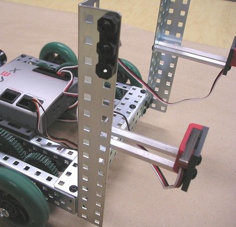
Part I: VexTM Starter Kit Projects

        There are many cool Vex designs on the Internet (check out the photo gallery at
                                 TM

www.vexrobotics.com), but Murphy's Law dictates that you probably won't have enough
parts to build most of them. Vex Starter Kits seem to undergo 2 common fates: they
                                      TM

grow and multiply, bringing delight to their owners (while simultaneously emptying the
owner's wallet), or they occupy closet space, virtually untouched, until they eventually
end up on e-Bay. In particular, people who have used a simpler "stand-alone" system like
LEGO Mindstorms are sometimes surprised and disappointed by how little they initially
      TM

are able to do with the Starter Kit. The payoff with Vex comes later rather than sooner
                                                          TM

– with 8 motor ports and 16 sensor ports (vs. 3 motor and 4 sensor ports for LEGO        TM

Mindstorms NXT), an incredible level of complexity can be reached IF you're willing to
spend the money and the time.
        Alas, big IF! To be used effectively, a Vex Starter Kit will need to be added to
                                                    TM

at some point, but there are still a few fun things that you can do before you spring for
more parts. Here are a few projects that use only the Starter Kit. If you are careful about
cutting, you can build and rebuild all of the projects shown here. Hopefully, with a few
projects under your belt, you can make a better decision about whether to and what to
invest in.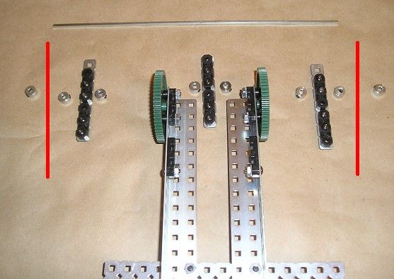
Squarebot

Project Description: Robust, highly maneuverable, 4-wheel drive robot.

Kits Needed: 1 Vex Starter Kit

Cut Pieces Needed: none

Bill of Materials: See the Vex Inventor's Guide, which can be downloaded here:
http://www.vexrobotics.com/docs/inventors-guide/main/vex-inventers-guide-9-27-06.pdf

Build Sequence: See the Vex Inventor's Guide.

Project Notes and Engineering Principles:

Gearing and Direction of Motion
        The Squarebot has 3 gears on each side. Watch how the motor drives the center
gear, and the 2 side gears are driven. These wheels will turn in the directions as shown
below:

Note that the direction of rotation alternates back and forth from one gear to the next.
Thus, gears with an odd number of gears in between (like the 2 end gears shown above,
with 1 gear between) will turn in the same direction, while gears with an even number of
gears between (including 0) will turn in opposite directions.

Drive Trains (Four-Wheel Drive)
        Note that each of the 2 motors on each side causes 2 wheels to turn, making this a
4-wheel drive robot. As a result, the Squarebot is highly maneuverable – it gets good
traction and is easily controlled. It is also relatively fast because of its geared-up
configuration (more on that in the next project). Two-wheel and 6-wheel drive are also
commonly used. There are other types of drive trains which allow wheels to operate
independently of each other or the chassis, including holonomic drives and swerve drives.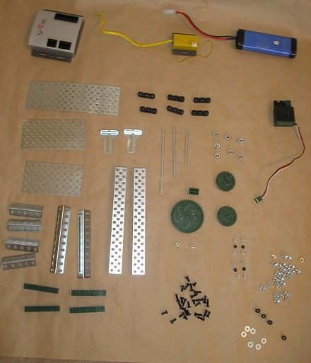
Flexigearbot

Project Description: A 2-wheel drive robot whose main design feature is the easy
exchange of gears. It converts from geared up to geared down to geared with a 1:1 ratio
in under 5 minutes.

Kits Needed: 1 Vex Starter Kit

Cut Pieces Needed:
1 square bar (axle), 6" (optional – an uncut 12" axle can be used if you have no other
    axles beyond the Starter kit and wish to keep 12" axles uncut for other projects)

Bill of Materials

1 microcontroller                          1 metal plate (5" X 15")
1 RF receiver module                       1 chassis bumper
1 antenna sleeve holder                    4 chassis rails
1 antenna sleeve                           1 long square bar (6" preferred, but 12" OK)
2 motor modules (NOT servo motors)         4 square bars (3")
1 battery pack                             36 keps nuts
2 small wheels (with rubber tires)         6 small plastic spacers (.182)
1 small wheel hub (rubber removed)         10 bearing flats
2 large (60-tooth) gears                   14 collars
2 small (12-tooth) gears                   4 small motor screws (1/4")
4 medium (36 tooth) gears                  32 medium length screws (3/8" or ½"—use
                                           the 3/8" in tight corners)
                                           4 long screws (3/4")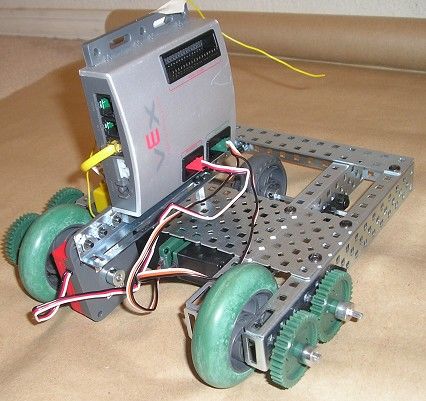
Build Sequence

Attach bearing flats to the chassis rails as shown. The center pair of flats is attached to the
middle row of holes, closest to the edge with screws facing up. The outer pair of flats is
located in the last row, offset 3 holes from the edge with screws face down. The rails are
mirror-image symmetrical, not identical.

Attach a chassis bumper to the ends nearest the bearing flats offset by 3 holes.

Attach a metal plate to the chassis rails as shown.
Turn the chassis upside down and attach motors on the inside of the rails.

Attach bearing flats to 2 additional chassis rails as shown.
Turn the chassis right-side up and attach the 2 outer rails.

Insert 3-inch axles into the motors and anchor with a collar from inside the chassis.
Attach the wheels, using 2-inch axles. Anchor with 2 collars outside and 1 small spacer on
the inside of the wheel.

Attach the gears, anchoring with collars on the outside. This configuration (small gear
driving a large gear) is geared down.
Attach the castor wheel, anchoring with collars next to the wheel and inner rails. The 6-inch
axle is preferred (making the outer bearing flats extraneous), but a 12-inch axle may be used
if desired to avoid cutting.
                                                                               Alternate axle
                                                                               configuration.

Attach microcontroller, RF module, antenna, and battery. Plug motor wires into motor ports
2 & 3, using Channels 2 & 3 (forward and reverse joysticks) on the transmitter. Let 'er rip!
Alternate configurations:
Exchange the gears for a geared-up bot. Replace the large and small gears with 2
medium-sized gears for 1:1 gearing.
Project Notes and Engineering Principles
Gear Ratios
The speed of a robot largely depends on 1) how fast the motors are turning, 2) the
size of the wheels, and 3) the gear ratio connecting the driving motor to the driven
wheels. To better visualize the role of gear ratios, suppose a motor is connected to an
axle which turns a 60-tooth (large) gear. A single rotation moves this gear through 60
teeth. If this gear is coupled with a 12-tooth gear, one rotation will drive the small gear
through 60 teeth. However, since only 12 teeth are needed to produce a single rotation of
the small gear, this gear will make 5 complete rotations every time the large gear turns
once. This means that the wheel will rotate 5 times as fast as the motor. Causing the
driven axle to move faster than the drive axle is called gearing up. While going faster
may seem like a good thing, you can't get something for nothing, and what is gained in
speed is lost in torque, or strength of turning.The Flexigearbot has 3 configurations: geared up, geared down, and geared in a
1:1 (same) ratio. Try all 3 and test your robots for different parameters such as speed,
ability to climb a slope, ease of turning around obstacles, and effectiveness on different
surfaces, like tile, carpet, and gravel.
One factor that biases the outcome should be noted: the large gears are almost the
same size as the small wheels, and if the gears touch the ground (likely to happen on soft,
uneven surfaces like carpet), the friction will work against the wheel motion or with it.
When geared up, the gears oppose the wheel motion; when geared down, they assist it.
Quiz question: What type of gearing does the Squarebot use?
Two-Wheel Drive
This robot has 2 powered wheels and a "dead" castor wheel. Not surprisingly, 2-
wheel drive robots are often called castorbots. Castors may also be pivoting castors, like
those on a swivel chair, or they may simply be a low-friction object that drags on the
ground (sometimes called a skid). Rubberless wheels, omniwheels, and bearing blocks
are often used for castors. Because of the lack of traction, castorbots tend to be more
difficult to maneuver than 4-wheel drive robots.Ping Pong Shooter
Design and Build: Yolande Petersen and Ryan Schambers
Project Description: Mechanism which shoots ping pong balls up to 5 feet (easy project!)
Kits Needed: 1 Vex Starter Kit
Cut Pieces Needed: None
Bill of Materials:
1 microcontroller 4 bearing flats
1 battery 6 keps nuts
1 RF receiver 4 small screws (1/4")
1 motor 6 medium screws (3/8" or ½ ")
2 motor screws 2 collars
4 threaded beams, ½ " 4 large spacers
2 threaded beams, 2" 4 small spacers
1 chassis rail 2 intake rollers
1 plate 5 X 15 holes
2 large gears (60-tooth)
2 square bars (axles), 3"Build Sequence: Attach motor to middle row of chassis rail. Attach bearing flat to the inside of chassis rail, leaving the middle hole empty. Attach threaded beams to chassis rail in the middle row
Insert axle into motor. Anchor one end of second axle and feed it through bearing flat.

Attach gears to axles. Add one large and one small spacer to each axle.

Add an intake roller and large spacer to each axle
Attach 2 bearing flats to the middle row of the plate as shown. Hole positions will correspond
to the axle positions.

Feed the 2 long screws through the plate, then screw on ½ " threaded beams until the screws
are flush with the beams.

Join the ½ " and 3" threaded beams by screwing the rest of the long screws into the 3" beams.
Anchor the non-motor axle with a collar.
Attach ½" threaded beams to the bottom. These lift the front of the device, providing a bit of
a ramp for the balls to launch. Turn the device right-side up, and feed the ping pong balls
from the bottom of the ramp into the intake device. Attach battery, RF receiver and motor
wire to microcontroller (e.g. to motor port 3), using the joystick (channel 3) to activate the
motor. Watch your fingers!

Project Notes and Engineering Principles
        This project is fun and quick to build, but not particularly profound. It does
demonstrate use of the intake rollers for grabbing, a common practice in competition
when trying to score a large volume of objects, like balls or rings.
Animal Grabber – Part 1: The Gripper Project Description: Mechanism which grabs and lifts squishy objects about 3-inches in diameter. Kits Needed: 1 Vex Starter Kit (plus 1 extra plate 5 X 15 holes, if available) Cut Pieces Needed: 2 long bars, 10 holes 2 long bars, 9 holes, 3 long bars, 6 holes (or slightly longer) 2 angle bars, 2 ½ " (Note: one long bar, 25 holes cuts nicely into 10 + 9 + 6 holes) Bill of Materials (for Parts 1 and 2) 1 microcontroller 2 angle bars (15" or shorter) 1 RF receiver module 2 angle bars (2 ½ ") 1 battery pack 2 chassis bumpers 2 motor module 4 chassis rails 1 PWM extension cable 16 bearing flats 4 large (60-tooth) gears 18 collars 2 small (12-tooth) gears 12 long screws (3/4") 2 square bars (12") 47 medium screws (3/8" or ½ ") 2 square bars (2") 59 keps nuts 2 or 3 plates (5"X15") – 3rd is optional 4 long motor screws 2 long bar strips (1 X 10 hole) 4 large spacers 2 long bar strips (1 X 9 hole) 13 small spacers 3 long bar strips (1 X 6 hole or longer) 1 long bar strip (1 X 15 or longer)
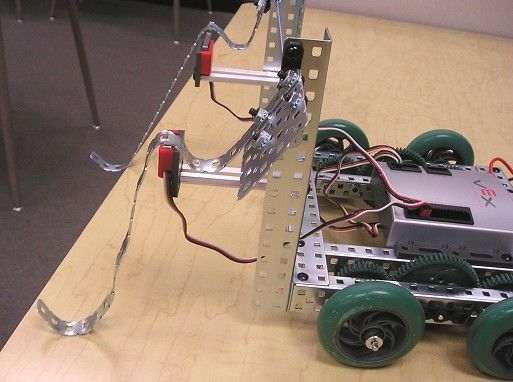
Build Sequence
Attach gears to 2½" angle bars, placing small spacers between gears and angle bars.

Attach 9-hole, then 10-hole strips to angle bars, separated by large spacers.

Bend strips until the ends meet, and attach the tips, separated by large spacers.
Attach bearing flats, motor, and "fingers." Nest gears so that the "fingertips" are more
or less symmetrically placed. Note that it's useless to attach a collar to the motor axle, as
this does not prevent the axle from falling out.

Attach motor to a microcontroller, battery pack, and RF module. You can now open and
close the pinchers. They move fast, because they're not geared down.
Project Notes and Engineering Principles:

        You may have seen machines where (for a "modest" fee), a claw will swoop down
and attempt to grab and lift a stuffed animal from a pile. Unfortunately, there is strong
motivation to use a poor design -- the worse the claw works, the more money it makes for
the vendor! This project is capable of lifting a small stuffed animal. Because of its
complexity, the project is divided into 2 parts: the gripper, and the lift.

Grippers (One-Axis Linear Grip)
        Imagine grabbing an object, like a soda can, with only your thumb and forefinger.
You would probably attempt to grab the can by either 1) pinching it with the tips of your
fingers or 2) encircling it with the entire length of the arc formed by your thumb and
forefinger. In the same way, a linear one-axis grip holds an object with either the tips of
its arms or by encircling it with its arms, the way you would hold onto a very large beach
ball. For round objects, the second method requires less force to hold an object, as the
greater contact surface provides more friction. The first method also requires that the
"finger tips" be positioned very precisely, but is better for picking up small, light objects
of irregular shape.
        To keep hold of the object, you have to continually keep the motor powered to
apply continuous pressure, or the pinchers will "let go", even if they remain closed. For
this reason, a continuous motor, rather than a servo (with motion limited to 120o of
rotation) is used, as a servo is capable of closing on the object but unable to move beyond
a certain point to apply the needed pressure. There are other gripper designs that keep
holding on without continual powering from the motor. These include 2-axis grips, roller
grips, and grips using bi-stable designs (having 2 stable positions: open and closed) such
as those activated by rubber bands or pneumatics.
Animal Grabber – Part 2: The Lift See Part 1 for Project Description, Kits Needed, Cut Pieces Needed, and Bill of Materials Build Sequence: Attach chassis bumpers for lift arms to the metal plate. Note that diagonal placement of the screws secures the bumpers in 2 dimensions with a minimum of 2 screws. Attach gears to the end of the lift arm, using small spacers to reduce gear friction.
Build the base. Slightly shorter angle bars (e.g. 12 ½" bars) also can be used for the base.

Assemble side supports, joining 2 chassis rails, and attaching bearing flats that will support the
axles.
Attach supports across the top and back, a minimum of 15 holes. A long bar (or bars) can be
substituted for the plate if necessary.

Assemble axle supports (ideally 6-hole bars, but slightly longer is OK).
Attach the lift arm to the frame, inserting the 12" axle through the collars, supports, and gears
in the order shown. Red lines indicate position of the frame.

                                                             Attach motor below first axle,
                                                             lining up holes for second axle.

Insert the lower axle, attaching gears and collars in the order shown.
Plug the battery, RF module, and motors (ports 2 and 3) into the microcontroller. Because this model is non-mobile, placement is flexible. However, a PWM extension cable is needed for the gripper motor, as the motor wire is too short when the lift is fully extended. Rear View Front View
Project Notes and Engineering Principles

Lifts
       One very important consideration in designing a lift is the amount of torque
required, which depends on the weight lifted and the length of the arm. It is important to
keep length of the lift arm to a minimum, as torque increases as you increase distance
from the weight to the pivot point. Even so, most lifts (including this one) need to be
geared down, trading speed for increased strength.

Bracing
        Another consideration in this design is that the weighted long axle tends to bend
downward, preventing the gears from fitting snugly together and causing them to slip.
For this reason, 3 braces are inserted between axles, keeping the distance between the 2
axles constant. Had the 2 side supports been placed closer together, the axles would have
less of a tendency to bend, making the braces unnecessary. However, this would produce
a narrower base, and the structure would be more likely to tip over. It is often necessary
to make tradeoffs like this.
        Various long bars and plates are used to brace the frame. The size of these
supports is flexible – pieces that hang over the edge are acceptable, even if they don't
look pretty. This is a concession to minimize cutting, as too-large pieces can be reused in
other projects that require larger pieces; once cut too small, they can't be increased in
size.
Part 2: Beginning Programming Projects
The ability to make robots that move autonomously (i.e., without user input) is
what distinguishes a true "robot" from a remote control vehicle. Without programming,
the capability of your powerful (and expensive, compared to a remote contolled car)
microprocessor goes to waste.
There are currently 3 programming options available. EasyC is icon-based and is
fittingly the easiest to learn. Because its commands are drag-and-drop icons, users
experience fewer syntax errors, as one cannot misplace stray semicolons and brackets. Its
disadvantages include slow download times and certain limitations that experienced
programmers find frustrating (novice programmers most likely won't know what they're
missing). ROBOTC is text-based, but menu driven. Because commands are typed, not
selected, it is more likely that syntax errors will occur. However, downloading of
programs is faster, and the language is more flexible than EasyC. ROBOTC is also
available for multiple hardware systems (including LEGO Mindstorms NXT), so learning
is transferable if you switch to a compatible system. MPLAB is generally recommended
only for experienced C users. More facts for comparison are available at:
http://www.vexrobotics.com/vex-robotics-programming-kit.shtml.
Because this guide is designed for beginners, EasyC is used. It is recommended
that you work through the tutorial that comes packaged with the CD in the programming
kit. If you did not receive a tutorial, it can be downloaded here:
http://www.vexrobotics.com/docs/inventors-guide/programming-guide.pdf
In addition to the programming kit, you may want to purchase additional sensors.
The Kentucky Do-Nothing and the Edge Detector make use of sensors already included
in the Starter Kit, the bumper switch and limit switch. The other sensors (line follower,
ultrasonic range finder, optical shaft encoder, and light sensors) must be purchased
separately. Soon-to-be released sensors include the potentiometer, compass sensor,
accelerometer, and gyroscope.
The required mechanical parts in these projects have been deliberately kept to a
minimum, using only parts in the Starter Kit. The Squarebot and Flexigearbot are
selected as the driving bases for simple construction. In some cases, the bases are
interchangeable. For others, the Squarebot is preferable for maneuverability, while in
others, the Flexigearbot is preferred for its lower gear-ratio, producing a slower robot
capable of more precise sensing. The programs are also simple (many with ideas
borrowed from other robotic systems) and are designed to demonstrate the use of one
sensor at a time.
For debugging, there are 2 useful diagnostic tools at your disposal: the Online
Window and the Terminal Window (which displays the results of all "Print to Screen"
commands. More details on use can be found in Vex for the Technically Challenged.The Kentucky Do-Nothing
Project Description: Robot programmed to reverse direction whenever it bumps a wall
or obstacle.
Kits needed:
1 Starter kit
1 Programming kit
Cut Pieces Needed: None
Bill of Materials
1 Squarebot chassis
2 bumper sensors
8 screws
Build Sequence:
Attach one bumper to the front and one to the back.
Plug in motor wires (left wire to motor port 2, right wire to port 3). Insert front sensor
wire into digital input 5 and the back sensor wire into digital input 6 (located on the
analong/digital strip).
.
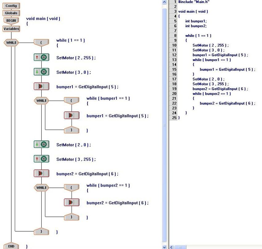
Programming and Operation
Enter the program shown below. Although variables are not visible from the
EasyC code, there are 2 variables that must be defined: bumper1 and bumper2. These 2
variables will hold the input from each of the bumper sensors, 1 or 0, and thus, the type
"int" (integer) is most suitable. To define variables, click on the "variables" icon in the
stack. For the first variable, under "Type", the drop-down menu will allow you to select
the type, in this case, "int" for integer. In the next box, the name of the variable should be
entered (bumper 1). No value is listed, since it will change value throughout the
program. The true C code shows the definition of these 2 variables.
It is advisable to hold the robot with its wheels off the ground (a stack of
paperbacks to prop up the center is effective) while downloading, as the robot will be off
to the races as soon as downloading is complete.
Place the robot in a narrow corridor (away from furniture and breakables) with the
bumpers facing opposite walls, and watch it bounce off the walls, reversing as it bumps.If the robot does not reverse unless the "wrong" bumper is pressed, you may have to
exchange the sensor wires in ports 5 and 6.
It is rare that 2 motors are perfectly matched, and if the walls are separated by too
great a distance, the robot will tend to veer, as the difference in speeds on either side will
cause the robot to travel in a curved or circular path. If there is enough space, it may
even bounce off the same wall, traveling back and forth in a semicircle.
The motor speeds in this program are set at 0 and 255, the maximum clockwise
and counterclockwise speeds. Choosing speeds closer to the "stop" position of 127, say
55 and 200 will cause the robot to travel more slowly. Any curving of the robot can also
be straightened to some extent by tweaking the motor speeds accordingly.
Project Notes and Engineering Principles
This beginning programming project requires minimal building skills. It does,
however, introduce the concept of using sensors to govern motion. The outer "while"
loop causes the robot to bounce off the walls indefinitely, until the robot is turned off.The inner "while" loops serve as sensor watchers – the program keeps the motors running
in the same direction and keeps looking at the bumper sensor until a change in value is
detected.
The bumper sensor is a digital sensor, with possible readings of 1 (not pressed) or
0 (pressed). The default designation of analog/digital inputs and outputs is:
Ports 1 – 4: Analog inputs
Ports 5 – 10: Digital inputs
Ports 11 – 16: Digital outputs
The ports can be reconfigured if desired by double clicking on the "Config"
button at the beginning of a program and using the right and left mouse buttons to change
the input/output type of each port. Reconfiguring the 4 analog ports into digital ones
would allow you to use ports 1 – 4 as digital inputs for this project.The Scaredybot
Project Description: Robot programmed to back up whenever an "intruder" approaches it
within 10 inches or less.
Kits needed:
1 Starter Kit
1 Programming Kit
1 Ultrasonic Sensor
Cut pieces needed: none
Bill of Materials:
1 Squarebot chassis
1 ultrasonic sensor
2 medium screws
2 keps nuts
Build Sequence:
Attach ultrasonic sensor to front of Squarebot chassis.
Plug left and right motor wires into motor ports 2 and 3. Plug the "Input" wire from the
ultrasonic sensor into analog/digital port # 11 (this is a digital output). Plug the "Output"
wire into interrupt port # 1.
Programming and Operation:
Download the following program. The variable "variablename" should be
defined as an integer; it records the distance of the nearest obstacle, as detected by the
ultrasonic sensor. The Scaredybot is antisocial – leave it alone and it sits placidly in
place; walk into its "personal space" within a few inches of the ultrasonic sensor, and it
backs away from you.
If an obstacle of is detected 10 inches away or nearer, the robot is programmed to
back up for 1 second, and the cycle of waiting for the next "intruder" continues.Project Notes and Engineering Principles
When triggered, an ultrasonic sensor emits a high frequency ultrasonic signal
which bounces off the nearest obstacle, returning to the sensor. As soon as the signal is
sent, a timing loop on the microcontroller begins, which ends when the return signal is
received. The time interval between signal sent and received determines the distance
between the sensor and the nearest obstacle. A digital output from port 11 is used to
trigger the start of the signal. The input is received through interrupt 1, and the variable
receives and stores this number as the approximate distance in inches, calculated using
the time interval.
The range of readings for the ultrasonic sensor is between 1 and 99 inches;
accurate readings for distances as close as 3 inches can generally be obtained. Distances
farther than 30 inches may be irregular and inconsistent – interfering factors which may
produce unpredictable results include robot movement and the tilt of the sensors (toward
or away from the floor).Edge Detector
Project Description: Robot programmed to move away from the edge of a table,
preventing it from falling off. It will also keep itself in the center of a room, moving
away from walls.
Kits needed:
1 Starter kit
1 Programming kit
Cut Pieces Needed: None
Bill of Materials:
1 Squarebot chassis, preassembled 4 bearing blocks
2 limit sensors 12 keps nuts
4 threaded beams, 3" 2 large spacers
20 medium screws 2 collars
2 extra chassis bumpers (angle bars 7.5" or 1 square bar (axle), 12"
longer are OK if you only have the 2 plates, 3 X 3 holes or larger (4 X 5 plates
Starter Kit) are used here)
2 bearing flats 2 long bars, 25 holes
Build Sequence:
Attach 2 vertical supports to Squarebot chassis (bumpers or angle bars)Attach light sensors to vertical supports with threaded beams. Attach bearing blocks to the sides of the vertical supports, leaving the bottom hole empty. Insert axle through the bottom holes, anchoring with collars on the inside, spacers on the outside.
Assemble "arms" as shown.

Slide bearing blocks onto axle ends. The "arms" can be flipped forward or backward and
should not bump against the bearing flats mounted on the vertical supports – use more spacers
if needed. Anchor with a collar.

Bend the "arms" around the limit switches so that they almost touch the switch when resting
on the ground. When an arm reaches the edge of the table, its weight should depress the
switch. The switch should also be pressed when the arm bumps into a wall or barrier. Plug
the motor wires into motor ports 2 (right) and 3 (left), the sensor wires into digital inputs 5
(right) and 6 (left).
Programming and Operation

        Enter and download the following program, which looks at both the left and right
sensors from digital inputs 5 and 6. Define the variables "left", "right", and "sum" under
"Variables" as integers. To operate, place the robot on a tabletop with both arms
supported by the table. Note that when the robot reaches an edge, one of the arms is
unsupported, triggering the limit switch. The robot backs up and swings in the opposite
direction of the arm that fell off (it attempts to get closer to the center of the table). The
robot also can be used to detect walls.
Project Notes and Engineering Principles
The limit sensor, like the bumper sensor, is a digital sensor, with possible readings
of 1 (not pressed) or 0 (pressed). The sensor loop continues while neither limit sensor is
pressed (sum of 2 sensor readings = 2). When either sensor is pressed, the robot backs up
and turns (direction depending on which sensor detects the edge), then repeats by going
forward toward the edge again.Line Follower Project Description: Robot programmed to follow a black line using a single line follower sensor. Kits needed: 1 Starter Kit 1 Programming Kit 1 Line Tracker kit Cut Pieces Needed: 1 long bar, 9 holes Bill of Materials: 1 Flexigearbot, preassembled (using 1 gusset plate 1:1 gearing w/ 4 medium gears) 5 medium screws (3/8" or ½") 1 Line Tracker sensor 5 keps nuts 1 long bar (9 holes) Build Sequence: Assemble the flexigearbot. Attach a 9-hole strip to the front. Attach the line tracker sensor to the front using a gusset plate (bottom views)
Plug left and right motor wires into ports 2 and 3. Plug the line follower sensor into
analog input 1.

Programming and Operation
        The variable "light" should be defined as an integer under "Variables." Then
enter and download the program shown below.
        A threshold of 650 was chosen to separate "light" from "dark", as the lighting
conditions in the room varied between 30 and 600 for "white" and >700 for "black."
Depending on the lighting in your room, this value may need to be adjusted. Motor
speeds of 64 and 192 were chosen so that the robot travels slowly enough for the sensor
to detect the line before driving completely over it.
        The robot should be placed on the left side of the line (as it faces forward).
Project Notes and Engineering Principles:
The line tracker sensors give readings between 0 and 1023, with 0 being brightest,
and 1023 being darkest. The readings vary greatly depending on the lighting conditions
in the room and the distance from the sensor to the surface being read. More accurate
readings with less variation occur when the sensor is as close to the marked surface as
possible.
This line follower follows the edge between black and white on the left side of a
line. It starts on the left and first "looks for" the line on its right. When sensor readings
cross the threshold from light to dark, the robot turns away from the line briefly, then
turns toward it again, until it finds it. It continues to follow the edge between white and
black, as long as the black is on the right and the white is on the left.
If the line is too thin or the corners are too sharp, the robot will drive over the line
without detecting it. Driving more slowly is one way to solve this problem; for this
reason the 1:1 configuration of the Flexigearbot was chosen (rather than a geared-up botlike the Squarebot). In addition, the motors were programmed to run at speeds of less
than full capacity.
Further Challenges
Can you devise a line follower that uses 2 sensors that straddle a black line?
What advantages and disadvantages are there to this arrangement? How about a 3-sensor
line follower?Boomerang
Project Description: Using remote control, the user moves a robot a desired distance, and
programming returns it to its original position.
Kits needed:
1 Starter kit
1 Programming kit
1 Optical Shaft Encoder Kit (Quadrature Encoder Kit may be used, but will require
reprogramming)
Cut Pieces Needed:
1 square bar (axle), 4"
1 angle bar, 5"
Bill of Materials:
1 Squarebot or Flexigearbot, (using 1 angle bar, 5"
1:1 gearing w/ 4 medium gears) 1 threaded beam, ½ "
1 optical shaft encoder 2 short screws, ¼ "
(or quadrature encoder) 5 medium screws, 3/8" or ½"
1 square bar, 4"
Build Sequence:
Replace the 3" axle on the right motor with a 4" axle. Mount the encoder on the axle. If
using a Squarebot, use replace one axle with a 4" axle and mount the encoder on the
outside of the wheel.Attach the encoder to the 5" angle bar. Stabilize the bar with ½" threaded beam,
attaching the beam at both ends with short screws.
Attach the microcontroller, RF module and battery, attempting to evenly distribute the
weight. Plug motors into motor ports 2 and 3. Plug the encoder wire into interrupt port
2.
Programming and Operation:
Enter and download the program shown below, defining variables "encoder",
"stick", and "dist" as integers. Use the Channel 2 (the left joystick) to move the robot
forward a desired distance. When you release the joystick, the robot should return (more
or less) to its original position. There may be some discrepancy in position due to
slippage.Project Notes and Engineering Principles:
The optical shaft encoder flashes light through a series of cutouts to a light
detector. As the shaft rotates, the flashes are counted, with 90 counts equal to one full
rotation of the shaft. Unfortunately, the encoder cannot determine whether the rotations
are clockwise, counterclockwise, or a mixture, so the count must be stored in a variable
every time the direction of motion changes.
This program waits for Channel 2 (the left joystick) to move the robot forward,
then measures the distance it travels until the joystick is released and stores it in the
variable "dist". It then resets and reverses direction until the encoder rotation equals
"dist", returning the robot to its original position.
The program also demonstrates the ability to read input from an R/C channel, as if
it were a sensor.
Further Challenge:
The program, as written requires that you turn the microcontroller off and on
every time you want to relaunch of the "boomerang". Can you modify the program so
that the robot can be launched and returned until you get tired of playing with it?Light Seeker Project Description: Robot programmed to follow a stationary or slow-moving light source. Kits needed: 1 Starter Kit 1 Programming Kit 1 Light Sensor Cut Pieces Needed: none Bill of Materials: 1 Squarebot chassis 1 motor module 1 light sensor 1 bearing flat 1 lock plate 2 motor screws 1 gusset 1 square bar (axle), 2" 11 medium screws 1 small spacer 3 keps nuts 4 threaded beams 1 plate, 5 X 15 holes Build Sequence: Attach lock plate to bottom of gusset, leaving center (square) hole open. Attach light sensor to side of gusset.
Attach motor and bearing flat to plate; insert axle.

Add small spacer to axle, then insert axle through lock plate attached to gusset.

Attach threaded beams to 4 corners of plate, and mount on Squarebot chassis.

Programming and Operation:
        Download the following program, defining the variables "leftlight" and
"rightlight" as integers. This light seeker samples light readings from 2 positions (left
and right) and uses the relative light readings to go in the direction of the lightest
(brightest) reading. It functions best when there is a single source of light in an
unambiguous, stationary location (for example, a dark garage with a single window). It
can also follow a flashlight if the light moves slowly enough, as the sample time for the 2
readings is slow – "wait" commands were required in order for the sensor to obtain stable
readings.
Optional program improvements
The program above can be improved upon in many ways. Probably the most
obvious of these is timing. The robot always spins for 0.2 seconds before moving
forward, and always moves forward for 0.5 seconds. These values can be tweaked to
enhance precision; ideally the robot's "spin" should leave it facing exactly the same
direction that its eye was facing, rather than in approximately the correct direction.
Notice that the program follows the same loop: the mounted eye always looks left,
then right. This means that the beginning of each loop, the eye must move from looking
right to looking left before moving from looking left to looking right. What if the eye
had two cycles that it alternated between: looking left before looking right, and looking
right before looking left?
Also consider that the program commands the robot to stop moving while it scans
the environment for light sensor readings. Could the efficiency be improved if the robot
continued moving forward while sampling the light? What if the robot simply reduced its
speed instead of stopping?
Project Notes and Engineering Principles:
The light sensor and the line follower sensor are both light sensors, but there are
slight differences in structure and function. The line follower sensors emit light, which is
reflected off a light or dark surface and detected by the sensor. Readings are best
obtained when the sensor is very close to the surface reflecting the emitted light. In
contrast, the light sensor does not emit or depend on reflected light. Instead, it uses a
photocell, whose resistance varies with the amount of light, and the source of light or
reflecting surface does not necessarily need to be close. The variable resistance readings
are analog values, with the lowest values (near 0) indicating brightness and higher values
(near 1023) indicating darkness.
This light seeker compares the light values to the left and right, and drives an
incremental distance toward the direction which gives the lower (brighter) value.Part 3: Advanced Mechanical Projects
Cool kits with advanced mechanical parts are available, but without knowing how
to use them properly, they too, can become expensive closet hogs. We wanted to include
projects that give a taste of what can be done with a few nifty doodads. These include
advanced gears (differential, bevel gears, and rack gears), chain & sprockets, tank treads,
and omniwheels. Use of the servo motor is also introduced here, as well as more
complicated gearing assemblies.
As you become a better builder, you will hopefully become more comfortable
with taking short cuts, making substitutions, and constructing subassemblies in a different
order than they may be presented here, as well as making design modifications and
improvements. There are always better ways to do things, and it's up to you to find
them.Tricycle Drive
Project Description: Alternative drive, using one control for forward/reverse movement,
and one control for steering.
Kits Needed: 1 Vex Starter Kit
1 Advanced Gear Kit
1 Chain and Sprocket Kit
Cut Pieces Needed
2 square bars, 6"
1 square bar, 4"
2 angle bars, 2 ½"
1 angle bar, 5"
Bill of Materials:
1 microcontroller 2 square bars (6")
1 RF receiver module 1 square bar (4")
1 antenna sleeve holder 2 square bars (3")
1 antenna sleeve 1 square bar (2")
1 battery pack 4 threaded beams (2")
1 motor module 37 keps nuts
1 servo module 13 collars
3 small wheels 2 large spacers
1 differential 2 small spacers
3 bevel gears 3 lock bars
1 medium (36-tooth) gear 11 bearing flats
1 large sprocket 3 long motor screws
1 medium sprocket 1 short motor screw
~ 9" sprocket chain 5 screws (¼ ")
4 chassis rails 6 screws (3/8")
2 chassis bumpers 30 screws (½ ") – substitute 3/8" if short
1 metal plate (5" X 15") 2 screws (3/4")
1 angle bar (5") 2 screws (1")
2 angle bars (2 ½ ")Build Sequence: Snap 2 bevel gears into Insert 6" axles into differential, inserting bevel gear, differential anchoring with collars. Attach bearing flats to chassis rails.
Attach motor module to chassis rail. Insert axle and attach gear.

                                              Prepare chassis rail for left side of gears.

Add bearing flats to 2 additional chassis rails for outsides of bot.
Add a large spacer to axles, add wheels, and anchor with collars on both sides. Attach chassis bumpers to the front and back.
Attach threaded beams to the front of chassis. These will hold the steering drive.

Assemble supports for the steering
wheel.
Mount the steering wheel onto a plate, which enables attachment of servo (do not use
a continuous motor module here).
Attach sprockets and chain. It is very difficult to attach the chain while the sprockets
are on the axles without getting "slop" in the chain. To minimize the slack, estimate
the correct chain length and snap it into a circle, feed it around the sprockets, and
place the sprockets on the axle last, pulling the chain taut. If necessary, add or
remove a link or 2. Align sprockets so that the steering wheel is approximately
centered when the servo is in "resting" position.
Attach steering wheel assembly to chassis using threaded beams on both sides.

Attach microcontroller, RF module, antenna, and battery. Plug drive motor into
motor port 3, steering motor into motor port 1.
Project Notes and Engineering Principles:

Steering Drives
        Many simple robots are constructed with one motor on each side, using the
difference in speed for turning (these are called differential drives). Thus, the same
motors are used for controlling speed and direction. However, when you think of how a
"real" car is driven, only one control (the gas pedal) is used to drive forward, and a
separate control (the steering wheel) is used for steering. A robotics car-type drive
(whose steering mechanism turns the 2 front wheels) and a tricycle drive (with a 1-wheel
steering mechanism) use this principle.

                       Car-type Drive               Tricycle Drive

        In order for a car to turn, the inside and outside rear wheels must travel at
different speeds. With only one mechanism controlling forward motion, how is this
possible? One way is to use a differential or differential gear (not to be confused with a
differential drive which uses 2 motors). A differential distributes unequal amounts of
"spin" to the 2 axles on either side. Watch the motion of the axles in the differential as
your steering drive turns.
        One thing to note is that this drive does not accurate mimic the behavior of a car:
in a car, the front wheels are used for both locomotion and steering, whereas in this
tricycle drive configuration the back wheels are used for locomotion.
        This robot drives "counterintuitive", i.e. pushing the joystick up moves the robot
toward you, rather than away. This problem can be fixed in a number of ways, including
1) rebuilding the robot as a mirror-image, 2) reprogramming the channels in the
software, reversing the direction of the motors, or 3) reprogramming the transmitter.

Chain and Sprocket Uses
        In this project, the chain and sprockets are used to transfer motion from one place
to another. Gear trains also accomplish this, but a big advantage of using chain and
sprockets is that a desired gear ratio can be maintained without being limited by the size
of the gears – the 2 axles can be close together or far apart, and the distance doesn't have
to be an exact multiple of a certain gear size. The main disadvantage is that chain is quite
fragile and is likely to break in a competition environment, especially if it is exposed and
taut. Use sparingly.
Cup Crusher
Project Description: Device translates a motor's rotational motion to linear motion
capable of crushing a cup.
Kits Needed:
1 Starter Kit
1 Advanced Gear Kit
Cut Pieces Needed:
2 angle bars, 5"
2 angle bars, 2 ½ "
Bill of Materials
1 microcontroller 1 square bar, 5"
1 RF module 1 square bar, 4"
1 battery 1 square bar, 3"
1 motor module 7 collars
1 plate 5 X 15 holes 1 worm gear
1 plate 5 X 10 holes 1 large gear (60 tooth)
1 plate 5 X 9 holes (5 X 10 also OK) 2 gears, 24-tooth
4 angle bars, 2 ½ " 2 long motor screws
2 angle bars, 5" 12 short motor screws (for rack gears)
4 rack gears 27 medium/long screws
6 bearing flats 27 keps nuts
2 gussets 3 large spacers
2 chassis rails 1 small spacer
6 plastic washersBuild Sequence Attach gusset to 9 X 5 hole plate (a 10 X 5 may be used for a more symmetrical, equally functional design, with plate extending an extra row beyond the edge of both gussets). Align another gusset on right, but do not attach. Turn plate upside down. Attach bearing flats as shown.
Turn plate right-side up and attach 2 ½ " angle bar.

Attach 2 ½ " angle bar to motor.

Attach bearing flat to 2 ½ " angle bar, and attach angle bar to plate.
Slide axle into motor, with worm gear and anchoring collars as shown. These will be
readjusted when the large gear is placed.

Attach rack gears to the middle row of holes in chassis rails. Connect racks loosely to slotted
portion of angle bars – the width of the frame will depend on the nesting of gears, which will
not necessarily correspond exactly to a fixed hole position.
Place rack inside gusset edges, adjusting the width of the frame so the center plate slides
smoothly along the sides of chassis rails. Place axles in bearing flat holes, add large spacers
and 24-tooth gears. Tighten when gears are nested with optimal placement – smooth turning
with minimal wobble and minimal friction. Screws in the slots will need to be very tight, as
more slippage occurs in the slot than would occur with holes.
Attach bearing flats to 5 X 10 hole plate, leaving center holes open.

Place 3 plastic washers on each axle. Turn plate upside-down and slide over axles, with
bearing flats on the inside.
Attach 2 ½ " angle bar to bottom of plate, opposite the angle bar on other plate. Tighten
collars on the ends of axles. Flip frame and push axles through.

Place large (60-tooth) gear on left axle, and spacers (1 small, 1 large) on the right axle (these
are used to prevent the gear from rubbing on the right collar. Anchor the gear and spacers
with collars. Adjust the position of the worm gear so that the large gear nests properly.
Tighten the collars on the sides of the worm gear – these will have a tendency to slip if not
properly tightened.
Add a plate to the bottom so the device stands up.

Attach motor to microcontroller motor port, battery, and RF module to operate with the
transmitter. There is sufficient torque to crush a paper or Styrofoam cup.

Project Notes and Engineering Principles:
         This project demonstrates the use of a rack and pinion system which translates
rotational motion from the motor to linear motion, with the circular pinion engaging teeth
on the rack gear.
         The worm gear is used to greatly gear down the motor. The worm gear operates
like a screw, with each full rotation of the axle causing the gear to advance by one thread.
With the threads nested between the teeth of the 60-tooth gear, each turn rotates the large
gear by only one tooth, producing a 60:1 geared down ratio. Thus, the pinion system
moves up and down the rack quite slowly.
         Even with this extreme gearing down and corresponding increase in torque, there
is still not enough force to crush an aluminum can. More torque could be produced by
attaching a second motor (turning in the opposite direction so that the motors operate in
tandem) and/or gearing down even further.
Holonomic Drive
Original design: FVC #3053, ’06-’07, Occam’s Engineers, posted at
http://www.chiefdelphi.com/media/photos/28621 and photo 28620 (used by permission).
Design modification and build: Alan Schambers.
Programming: Justin Petersen
Project Description: Another alternative driving base, allowing robot to be easily shifted
in all directions.
Kits needed:
1 Starter kit
2 extra chassis bumpers
1 Extra Motor
4 Omniwheels (large or small)
1 Programming Kit
Cut Pieces Needed: None
Bill of Materials
1 micro controller 8 bearing flats
1 RF receiver 8 threaded beams, 3"
1 battery 4 motors
2 plates, 5 X 15 8 short motor screws
4 chassis bumpers 4 axles, 3"
4 chassis rails 4 small spacers
16 short (1/4") screws 4 large spacers
36 medium (3/8" or 12"screws) 4 collars
36 keps nuts
Build Sequence:
Assemble the ChassisAttach the motors Attach supports and omniwheels
Attach outside rails

Attach the microcontroller, RF module and battery

Attach the motor wires - motors labeled 1, 2, 3, 4 plug into ports 1, 2, 3, 4
Viewed from the bottom, the motor numbers go counter clockwise
Programming and Operation:
The following program allows the left joystick to shift the bot up/down/left right.
Project Notes and Engineering Principles:
A holonomic drive enables a robot to rotate in place, move in any direction, or do
both at the same time. This bot is fairly simple to build and fun to drive. The left
joystick is used to shift the robot up/down/left/right. The program included must be
downloaded for the drive to work properly.
Further Challenge:
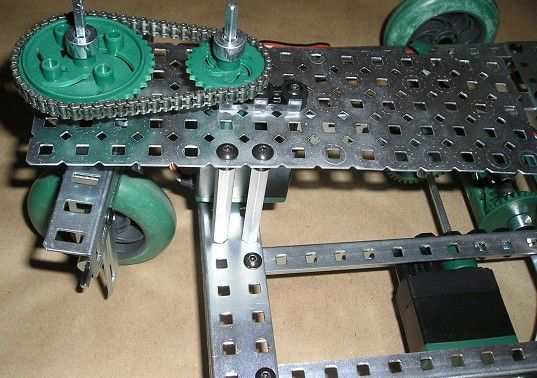
Can you program this bot to spin, as well as shifting in the 4 directions?Chin-upbot
Design and Build: FVC #3617, Metal Gear ('06-'07)
Project Description: Robot designed to lift itself off the ground from a 30-inch high bar.
Kits & Parts needed:
1 Starter Kit
1 Gear Kit (4 extra 60-tooth gears)
1 Metal and Hardware Kit
1 Extra Motor
Note: An alternative to all these add-ons to the Starter Kit is to buy a second Starter Kit.
Cut Pieces Needed:
3 square bars (axles), 8"
2 square bars (axles), 6"
3 angle bars, 5"
1 angle bar, 7.5"
Build Sequence
Build the Squarebot or alternative driving base (the Flexigearbot is not recommended as a
driving base). Remove the chassis bumper on one end.
Construct the arm as follows:
Build supports for the gear assembly:Build the lower joint gear assembly, using the three 8-inch axles.
Add the second joint and upper arm
Attach the arm to the robot chassis. This is easier to do if the arm is folded as in the first
photo in the chin-up sequence below (plug in the upper arm motor into a motor port and
use the appropriate transmitter channel). Plug the drive motors into motor ports 2 and 3,
and plug the arm motors into ports 5 and 6 (channels 5 and 6 are the yellow buttons
located on the bottom of the transmitter).

To perform a chin-up, unfold the arm, drive the robot forward until it grabs the bar, then
fold the lower hinge only to lift the robot off the ground.

Note that this robot is rather unstable (it tips easily) because of the small size of the base
and high center of gravity when the arm is extended. A longer driving base would
provide more stability.
You can also read