ER-Force 2019 Extended Team Description Paper - Small Size League | RoboCup ...
←
→
Page content transcription
If your browser does not render page correctly, please read the page content below
ER-Force 2019
Extended Team Description Paper
Theresa Engelhardt, Tobias Heineken, Tobias Kuehn, Jeldrik Lindner,
Mike Schmidt, Felix Schofer, Christian Seifert, Michael Stadler,
Lukas Wegmann, Andreas Wendler
Friedrich-Alexander-Universität Erlangen-Nürnberg (FAU), Faculty of Engineering,
Department of Computer Science, Distributed Systems and Operating Systems
Robotics Erlangen e.V., Martensstr. 1, 91058 Erlangen, Germany
Homepage: http://www.robotics-erlangen.de/
Contact Email: info@robotics-erlangen.de
Abstract. This paper presents proceedings of ER-Force, the RoboCup
Small Size League team from Erlangen located at Friedrich-Alexander-
University Erlangen-Nürnberg, Germany.
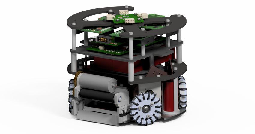
Fig. 1. ER-Force robot design from 2018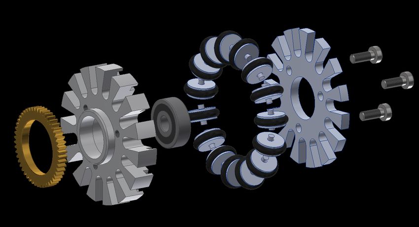
1   Introduction

In the last years, we participated at the RoboCup with the same generation of
robots. To keep up with the league, we need faster acceleration, better dribbling
and more. Therefore we undertook a complete redesign of our robots and are
currently building the new generation of improved robots. The core improvement
is the use of 70 Watt drive motors instead of 30 Watt. As the major changes in
the last year took place in the hardware, it will be the main focus of this paper.
    Section 2 describes some of our key changes in the mechanical construction
of the new robots. Section 3 outlines important considerations that we took
into account while designing the improved electronics for the new robots. In
section 4, adaptions of our software to the increased field size are outlined as
well as some general insight on how to avoid human error during tournaments.
Finally, section 5 includes tips on keeping an SSL team alive and successful.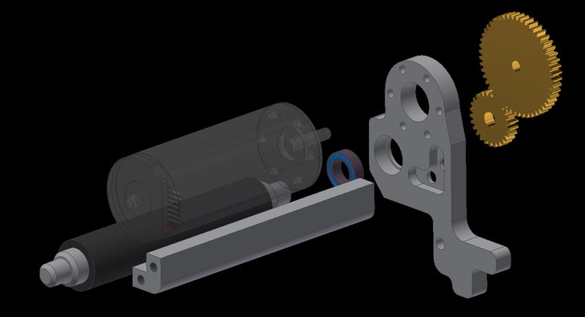
2     Mechanics

2.1   Dribbler

An important aspect of constructing our new robot generation was redesigning
our dribbler-module, including the dribbler panels and the suspensions. With
these design changes we tried to address a fundamental problem of our previ-
ous generation of robots: inconsistent behavior when catching, controlling and
shooting the ball. These problems are the result of three different issues: awry
dribbler rolls, interrupted break beam, and reacting forces pushing the ball out
again.

Dribbler roll Our dribbler, both the old and the new version, consists of four
parts: the dribbler roll, one dribbler panel on each side, and an L-shaped spacer.
The dribbler roll, which is responsible for ball manipulation, is being held in
place by the dribbler panels. These have to be perfectly aligned to make sure the
dribbler roll will act as deterministically as possible. The alignment is established
by the L-shaped spacer. Previously, the spacer has been attached to the panels
by two screws on each side. This, however, allowed the two panels to twist in
reaction to strong external forces due to the nature of the frictional connection.
The twist then broke the alignment of the panels and caused indeterministic
behavior. This manifested in different shooting angles between individual robots
which could also change over time. To avoid this we added slots in both panels
to interlock the L-shaped spacer as shown in figure 2.

Fig. 2. Our new dribbler assembly showing the dribbler roll, L-shaped spacer and one
dribbler panel
Break beam A similar problem occurred with our break beam. The emitter
and the receiver are mounted inside the dribbler suspensions, one on each side
of the robot. These suspensions are mounted on the base plate using two screws
each. If these parts rotate slightly in reaction to collisions with other robots
or too much torque during assembly, the direct connection of the light beam
is interrupted. This is an important factor that led to undefined break beam
behavior. To guarantee the correct alignment we placed slots for the suspensions
in the base plate.

Reacting forces The final change regarding our dribbler module concerns re-
acting forces. The force distribution that arises when the ball strikes the dribbler
is illustrated in figure 3.

                              20%

                     FA       FAy

                  Dribbler

                                                    Ball
                        FAx         φ    FRx

                              FRy
                                            FR

              y

                    x

Fig. 3. Force Distribution at the Dribbler Roll; FA : resulting Force, FAx : force com-
ponent along X-Axis, FAy : force component along Y-Axis, FR : reacting Force to the
Ball, FRx : force component along X-Axis, FRy : force component along Y-Axis, φ: force
angle

    The force FA of the ball colliding with the robot acts vertically to the tangent
at the point of contact. According to the 3rd Newtonian law this results in the
responding force FR . This force can be split up into a vertical and horizontal
component. The horizontal force FRx is responsible for pushing the ball away
from the robot again. In order to minimize this force we placed our point of
contact as high as possible. However, the height of this point is limited by the
maximum allowed ball coverage as given by the 20 % rule. Therefore, we decided
to reduce the radius of our dribbler roll to push the point of contact even fur-
ther up, while maintaining low ball coverage. As a result of this, the angle φ is
minimized and a larger fraction of the force FR is directed towards the ground.
While decreasing the radius, we wanted to make sure to keep the circumfer-
ential velocity at least equal to the old velocity. This requires that Vold ≤ Vnew ,
where Vold is the speed of our old dribbler and Vnew of our new roll. We derived
the necessary gear ratio i using equations 1 and 2.
V =2·r·π·n (1)
nout
i= (2)
nin
These equations are part of the standard gear theory [1]. We assumed the
rotational speed of the dribbler motor nin to remain the same, as we did not
find any data about that.
After equating the velocities we get the result presented in equation 3.
noutnew rold noutold rold
inew = ≥ · = · iold (3)
nin rnew nin rnew
We used the old gear ration iold = 1.35, the old radius rold = 8 cm, and
the new radius rnew = 6.5 cm for the calculation. To get at least the same
circumferential velocity, a gear ratio of at least inew = 1.66 is necessary. Due to
geometrical restrictions we use an actual gear ratio of inew = 1.95 which further
increases the dribbler speed.
2.2 Drive module
We replaced the 30 W motors with 70 W motors from maxon motors to increase
velocity and acceleration of our new robot generation. Since our new motors
are about 10 mm thicker than the old models we had to adjust and reduce the
size of certain mechanical components: motor mounts, linear shot and chip kick
modules.
In order to improve the acceleration we changed our gear ratio between motor
and wheel by using a larger pinion with more teeth and a smaller gear with less
teeth for the wheel. We also added a new shoulder to ensure proper centering
of the gear. These changes dictated the inner and outer diameter of the gear,
leaving little room between the two. Therefore we used Loctite 638 to glue the
gear to the shoulder of the wheel instead of using screws as we did in the previous
generation. The entire wheel is shown in figure 4. The strength calculation of
the connection between gear and wheel body results in a safety factor of 63.4,
according to VDI 2229 (see appendix A for the calculation). We considered using
a gear made out of synthetic material, but these cannot be produced with the
necessary fit. We use brass and steel gears instead.
The pinion is glued on the shaft using Loctite 638 and the resulting connec-
tion has a safety factor of 5.6. The pinion has a larger diameter than the motor
shoulder. However, to make disassembly possible the pinion must fit through the
centering bore of the motor mount which is shown in figure 5. Due to the fact
that the radius of the motor shoulder is smaller than the radius of the centering
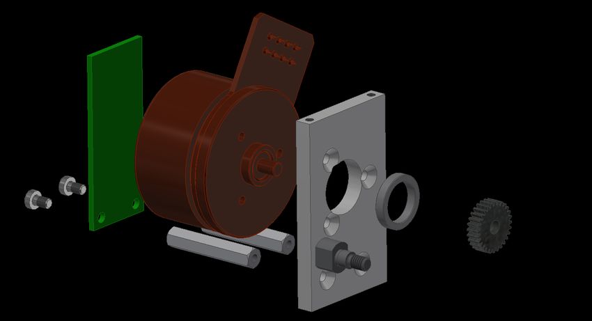
bore we had to add an adapter. These modifications lead to a gear ratio of 1.79.Fig. 4. Omniwheel Fig. 5. Drive Module
As a part of our module construction method we included the encoder system
into the drivemodule.
We are using a self-made magnetic encoder solution instead of the prebuilt en-
coders from maxon. To guarantee a smooth running robot the precise alignment
of the encoder and the magnet, glued concentrically to the back of the motor,
is important. For an accurate position the encoder and the corresponding board
are connected to the motormount by two spacers.

3     Electronics
3.1    Design Considerations for the New Generation
Improved Overvoltage Protection Over the years, more and more boards
refused to function due to the failure of specific front-end components. These
are parts, which share at least one pin with an interface connector. Among other
things, this lead to unprogrammable and in consequence unusable boards as well
as other sporadic and nondeterministic types of malfunction.
     Closer inspection revealed one common issue: All such error-prone pins had
little to no protection against overvoltage events such as transient voltage spikes
or were only unilaterally protected against such occurrences, i.e. only one side
of the interface connector was protected.
     The absence of security devices such as TVS diodes or varactors proved to
be a fatal decision: Especially for module-based concepts like our old and new
generation, events like electrostatic discharging (as described by the human body
model) happen a lot during the assembly and disassembly of the robot.
     For this reason, we decided to secure all signals which are accessible via mod-
ule interface connectors with appropriate transient voltage suppression devices.
Although this increases the price for each board by a non-negligible amount, the
measure will increase the long-term robustness of the electronic components.

Changed Signal Flow In the old generation the motor speed sensors were di-
rectly connected to the motor boards. Therefore, the speed control of the wheels
was running locally on each of the motor controllers. For our new generation,
the approach differs: Now, all the encoder data is gathered in one place, the
mainboard, and the resulting target currents for each motor are distributed via
CAN.
    One major advantage of this concept is that the central speed controller
knows all motor speeds at every time and can therefore control all motors simul-
taneously. This greatly improves the quality of our motor control, for example
it should now be possible to compensate for a broken motor.

Increased Supply Voltage Considering the fact that the batteries of our old
robots only lasted for one half of the game, we decided to double the supply
voltage for the new generation.
    With the new voltage of 30 V the required current is usually halved. Because
of the lowered current, the new generation benefits from reduced conduction
losses in the copper wiring. This is especially useful for our motor supply and
the charging electronics of our kicking mechanism which use a lot of current.
3.2 Redesign of Motor Controller Boards
The Problem
Introduction One of the most severe problems of our old generation are the
motor controllers, which significantly limit the capabilities of our robots due to
several serious issues. These issues exist mainly due to the poor choice of the
motor driver, a L6234 by STMicroelectronics.
In the following sections the individual problems of this motor driver will be
explained and a possible alternative is presented. As this issue also applies to
many other motor drivers of this kind, a general problem of heavily integrated
motor drivers is shown, which must be considered when choosing the right com-
ponents for motor boards.
No Possibility for Adjustments Due to the missing software and hardware inter-
faces, adjustments to the motor driver could not be made, neither pre- nor re-
configurations. Because hardware requirements like maximum acceleration con-
stantly rose as time passed on – unlike hardware capabilities –, this issue not
only got more and more problematic, but could not be handled by the motor
driver at all.
Additionally, the gate voltage of motor drivers like the L6234 – which do
have integrated half bridges – cannot be measured, hence, one cannot estimate
the time needed to fully turn on or off the output stage. This results in unknown
distortions of duty cycles, especially for small values. This problem generally
reduces the dynamics of the overall system and must be faced by the motion
control.
Excessive Heat Emission Another problem of the old motor controller is the
excessive heat emission at high currents. When we first developed the old gen-
eration this was not a problem as the currents were rather low compared to the
up to 3 A that we are currently using.
But after several improvements of our motion control, the heat emission be-
came a severe problem: The more dynamic approach made it possible to confi-
dently control even large torques resulting in large motor currents. To handle the
resulting motor controller losses, we had to install fans and heatsinks to prevent
the motor controller from reaching its overtemperature shutdown. Nonetheless,
we have not been able to exploit the full potential of the new motion control
system.
Unfortunately, due to the fixed conductive resistance of the internal half
bridges, this problem cannot be resolved in our old generation. As a result, the
dynamics of the robot is greatly limited by the overheating protection of the
motor controller. This limitation was one of the main reasons for our team to
start the development of a new generation.
Missing Diagnostics Functionality Because of a missing interface it was not pos-
sible to determine any failures or faults on the motorboard with the old motor-
controller. A faulty behavior like overheating, overcurrent etc. was not detectedand therefore never reported to the firmware. In such a case the firmware was
driving the motorboard to its full extent, damaging it further or even destroy-
ing it completely. As this issue only becomes noticeable as a dead board we
had to resort to guessing the root cause. This meant investing a lot of time for
trouble-shooting which we could have used otherwise.
Summary In conclusion, the most important reason for developing a new genera-
tion of robots from the electrical point of view is the ill-designed motor controller
board. Although it may seem that the performance of the board was quite good
according to measurements, with our robots having higher accelerations than
other teams with much stronger motors, this was rather due to our well-designed
motion control than the board itself. More precisely, the performance probably
would have been significantly better with more adequate motor boards fitting
the given requirements.
The lesson is that one should never assume maximum key features unless
necessary. Although some changes may always require a new generation of boards
to be designed, most of the adjustments can be avoided with a future-oriented
design. Instead of choosing components that barely fit current needs, one should
take into consideration that requirements will steadily increase over time and so
will the conditions for choosing the right components.
The Solution To fix all the above-mentioned problems, we decided to choose
the DRV8320S from Texas Instruments. Not only does this motor driver use
external half bridges, which greatly helps in controlling the on-state resistance
of the motor driver, but it also supports several kinds of diagnostic features like
overtemperature, overcurrent and undervoltage protection.
Furthermore, there are different modes of motor control: While the simple 1x
PWM mode only needs the hall sensors, the desired direction of motor rotation
and a PWM signal, the driver also features 3x PWM and 6x PWM modes for a
more independent motor control. The device also offers a wide range of PWM
frequencies, leaving open the possibility of implementing a field-oriented motor
control in the future.
To complement these strengths, the motor controller balances universality
with simplicity: Only those parts important for future approaches are realized
with external components, whereas aspects like generating the gate drive voltages
are dealt with internally. Necessary external components are depicted clearly in
the datasheet and an example schematics is given for guidance.
Other Improvements
Better Current Measurement In addition to the new motor controller, we also
changed the way of measuring currents. In the old generation, we only measured
the current at the supply pin of our motor driver. As this measurement reflected
the sum of both the actual motor current as well as that of the motor driver, an
inherent error in the form of an unpredictable extra current was made.In the new design, we use two current measuring devices of type INA240.
The key feature of this device is its capability of operating in series of a phase,
i.e. both at high and low voltage sides, whereas most of the other current sense
amplifiers can only operate at a limited common mode voltage range.
As we measure two of the three currents, the third one can be calculated
according to Kirchhoff’s Law. Furthermore, the total current through the motor
may be calculated by summing up all currents of equal sign. The result is a state
of perfect information: All currents known at all points in time.
This offers the possibility of implementing a field-oriented motor control in
the future, since a core component of this is the knowledge of all the motor phase
currents. But more importantly, we now have perfect control over the behavior
of the current sensor, i.e. over the measurement gain and hence the deflection of
the measured signal.
Separate Board for the Dribbling Device In our old generation, our motor boards
were designed to control both a regular motor as well as a dribbler. The addi-
tional dribbling feature is enabled if the board is attached to a specific mod-
ule slot. Unfortunately, treating the dribbler as a device of minor relevance
greatly limits its capabilities. This was especially noticeable during RoboCup
2018, where we faced severe difficulties in handling the ball due to self-imposed
restrictions on the dribbler. The following paragraphs describe these restrictions
as well as all issues that arose because of them.
The first problem is that the old dribbler is controlled by a completely differ-
ent set of components. While the regular motor had a fully developed three-phase
half bridge driver with ICs designed specifically for driving such kind of motors,
the dribbler only got a discrete driver (which was also due to the limited space
remaining on the board).
Furthermore, the usage of different components for the two types of motors
resulted in a totally different electrical behavior. Especially for parameters like
the serial resistance of the motor driver or the quality of current measurements,
this was quite an issue for the motion control.
In our new generation, the dribbler is controlled by its own yet compared to
regular motor boards schematically equal board. Therefore, it has the same set
of capabilities and available features resulting in some advantages compared to
the old approach.
• With a separate board, we can fully control and survey the dribbling motor,
both of which was only possible to a very limited extent before.
• Since the connection to the dribbling motor only had 2 phases, we were only
able to use simple DC-motors for dribbling. With a separate board, we can
now use three-phase motors, which are much more convenient and powerful.
• In our last generation, the firmware had to include extra code for handling
the DC dribbling motor. Now, all motors can be handled based on the same
code. Additionally, we no longer have to include controlling electronics for
the dribbler on every motor board.The only known disadvantage of this concept is that the new dribbler board
needs another module slot. As we already use five of our six module slots (four
motor boards and one flyback board) and there is no more space for more, no
more connections will be available in the future. This may become a problem if
there is a need for another module board at any time in the future.
Guideline for new Motor Controllers The following section is intended as
guidance for the development of new motor controller boards. It is structured as
a checklist and includes all points which proved to be important while developing
our new motor controllers. It is especially tailored to new teams and hopes to
give them further advice on how to design a future-proof motor controller board,
although it may be of help to all teams.
• Requirements for motor driver controllers:
◦ Is the chosen motor driver adjusted after development to fit future needs?
Is it possible to drive different kinds of motors? Can you drive a motor
to its full extent, i.e. field-oriented motor control?
◦ Does the motor controller have diagnostic features such as, but not lim-
ited to, overcurrent protection, over- and / or undervoltage protection,
overtemperature shutdown? Are they easily accessible and debuggable?
◦ Is the motor driver also suitable for motors and loads that exceed those
expected during the development of the board / the next few years?
• May the half bridges withstand higher voltages / currents than currently
expected? Are the efficiency of the motor driver and the half bridges high
enough, i.e. their thermal losses low enough to legitimate their use in a
battery-powered environment?
• Is the motor controller usable with higher voltages if necessary, to open up
the possibility of changing the motor without redesigning the whole board?
• Considerations for Board Design:
◦ Is the path of the motor supply current as short as possible and does it
enclose an area as small as possible to prevent electromagnetic interfer-
ence? Are the high current sections geometrically isolated from the rest
of the board? Are there appropriate capacitors and ferrites to prevent
spread of motor noise? Is small / mixed signal ground separated from
high current / high frequency ground?
◦ Is the path of the motor supply current thick enough to prevent sufficient
voltage drops and heating of PCB wire?
◦ Are sensitive devices such as MCUs protected sufficiently enough against
EMI, at least at ports which are schematically or geometrically exposed
to high current sections?
◦ Are there enough backup capacitors to store the energy needed for the
motor and the motor driver to work properly? Is the ESR and ESL
between the capacitors and the motor small enough to prevent high fre-
quency resistances and voltage spikes, i.e. is the motor locally decoupled
with high quality and high value capacitors?◦ Are current sensor paths as short as possible to prevent common mode
noise induced by the motor current? Are shunts chosen properly (at least
Kelvin wires, preferably special four-terminal Kelvin-Shunts)?
◦ Is it possible to install passive or active cooling if needed?
• Is the current sensor accurate enough for future applications which may
require higher dynamics and therefore lower measurement noise?
• Is the design centered around one component, which cannot be replaced
without changing the whole schematics (which would be bad)? Is it easy
to change the schematics if something needs to be adjusted to new require-
ments?
• Is the concept of your motor controller future-proof? Can it also suit higher
requirements than currently expected?4 Strategy (A.I.)
4.1 Midfield Strategy
The increase in field size from 2017 to 2018 posed a great challenge for our
strategy due to some formerly valid approaches not scaling up very well. This
section is about the issues we faced and how we overcame them. Specifically, the
following aspects needed improvement:
• Passing: When acquiring ball control, we try to pass it on to a striker close
to the opponent defense area. With the smaller 9x6 field, these passes were
relatively short and safe. With the increased field size, the same strategy will
lead to long passes that take a lot of time to arrive at their target and can
thus be easily intercepted.
• Man marking: On the defensive side, following the same line of thought,
focusing on intercepting these short passes was not all too promising. Instead
of blocking passes, we instead blocked any goalshot opportunities that a pass
target may have. With the facilitated intercepting opportunities, a different
manmarking strategy is needed.
Passing To solve these problems we put some thought and effort into midfield
strategies, which we had neglected until now. Moving the ball ahead in an easy
to control fashion requires the pass distance to be significantly reduced. Our
attack strategy [2] was sampling possible pass suggestion with the main goal of
creating goalshot opportunities. For the midfield we implemented a new group
of freebreakers that employ a different sampling method to supply pass oppor-
tunities that are difficult to intercept. Any position will be evaluated based on
the following criteria:
• Proximity to opponent robots
• Distance to the opponent goalline: the further ahead the better, we want to
move the ball forward
• Pass Distance: a middle ground needs to be found, passes that are too short
are useless, passes that are too long are uncertain
• Angle to striker robots: if we can forward the ball to a striker without stop-
ping it (volley pass)
• Angle to main attacker: if the main attacker can forward the ball to that
position without stopping it
• Time needed for the recipient to reach the position: of course, we need to be
able to reach the position in time
Some of these criteria are computationally intensive, so if a simple criterium
already disqualifies the position, it is discarded without calculating the final
rating. This enables us to sample a high number of positions to find a good po-
sition. Each midfield robot samples positions in a discrete region. These regions
are assigned by the trainer [2], a high-level coordination module of our strategy,
based on proximity and they do not overlap each other. The regions are spreadout in a way that allows for the ball to be repeatedly passed between midfield-
ers to quickly move the ball forward. When the ball moves further ahead, the
number of midfielders decreases. Eventually, the strikers take over and follow
the previous attack strategy.
Man marking Up until now, we did not judge aggressive man mark strategies
to be worth the effort, since the chances of success seemed too small to be more
viable than focusing on blocking incoming goalshots instead. However, if a team
puts little thought into midfield strategies they might be prone to utilizing long
distance passes which are significantly easier to intercept.
Since we do not want to miss out on these opportunities, we introduced a
new role to our strategy with a focus on manmarking. We call this role piggy,
after the children’s game "Piggy in the Middle". Adding another role leads to an
entirely new problem, we have to compromise between having more centerbacks
and having more piggies. To determine this number, we use the dangerousness
calculation [3] together with a new pass viability calculation. The pass viability
score rates opponents by how securely they can accept passes and how beneficial
these passes are for the opponent if they succeed.
It is calculated as follows: The list of opponent robots is first filtered to ignore
robots close to the opponent defense area, the ball owner and robots behind the
ball. We assume that passes will tend to move forward so marking these pass
opportunities are not worth the effort. The remaining pass targets are judged by
their distance to the ball and their distance to our goal. Long passes are easier
to intercept so targeting these robots is promising. Pass targets close to our goal
pose a threat so we want to intercept those as well.
The score is then compared to a threshold value that is related to the ball
position. When the ball is far away from the goal, the threshold decreases as
there is little threat to our own goal in that scenario. Pass targets which score
does not exceed the threshold are discarded. An inverse threshold is applied to
the dangerousness rating. That leaves us with only viable manmark targets and
dangerous opponents with possible goalshot opportunities. Dangerous robots
are prioritized in every case. When these are dealt with, manmark targets are
assigned to the remaining defenders. This ensures that we leave no openings in
our effort to intercept passes. Once a piggy has an assigned target, it will start
manmarking the robot. It will not stand in between the pass recipient and the
ball, as an AI may notice that. Instead, it positions itself with a perpendicular
offset to that line and simultaneously slightly ahead of the opponent. This both
tempts the opponent to pass to the marked robot nonetheless and also ensures
that our robot can be first at the ball when the pass actually happens.
4.2 Avoiding Human Error
We experienced time and time again at the RoboCup and private tournaments,
human errors in the configuration and usage of software, be it the vision or our
own framework, repeatedly affect the game negatively. Therefore, we strive to
minimize the possibility of misuse of our software during tournaments.The first adaption we included in our framework is called tournament mode. It
is motivated by multiple anecdotal accounts, for example the following situation
at IranOpen 2018: the opponent had a timeout and we made an adjustment
in our software. However, we were not finished when the opponent stopped its
timeout. We were not able to get a timeout instantly after the opponent timeout.
This left our software in a state in which it was not able to control any robots,
which led to a goal against us.
To avoid this and similar issues in the future, we implemented the following
changes that are active during tournament mode:
• Our software is started in a bash script loop, if it crashes due to segmentation
faults or returns a non-zero exit code, it will be restarted. There, it is always
started in tournament mode, so that all following improvements apply.
• Radio control and kicker charging is enabled by default. In our non tour-
nament setup, both are disabled by default to avoid accidents with active
robots. Manual control of robots is automatically disabled.
• Logging is always enabled. During states like Halt, Timeout or Half time,
logging can be disabled by the user, but it will automatically reactivate
itself once the game resumes.
• During non-game states, logs can be analyzed or simulated tests can be run
in our software. Once the game resumes, the simulation or log viewing is
automatically stopped and our strategy resumes control of the robots.
As we observed during RoboCup 2018, many teams set the side of the playing
field that the team defends manually in their software, even though the refbox
sends this information as ’blueTeamOnPositiveHalf’. We strongly advise to use
the provided information automatically as it reduces possible errors. Also keep
in mind to properly test this functionality with the real game controller on a
real field instead of inside a simulator with an internal referee.
For misconfiguration of shared software, we use a slightly different approach;
our software generates warnings for some problems. These could in theory also
be implemented in the shared software. Consider the following setup: there are
two vision computers, but they do not each have the maximum of 4 cameras,
which was done for performance reasons. It is possible to disable cameras in
the vision by setting the camera id to a negative number. If this is not done, a
default configuration is sent out for all cameras that are not explicitly calibrated
otherwise because they do not physically exist. When cameras are not properly
disabled, it may occur that one computer sends out default configurations for
a camera id for which the other computer has a proper configuration. If not
handled correctly, this can lead to a periodic exchange of proper and default
camera information like position in the team software. This proved detrimental
to our flight tracking software. Therefore, we advise to either ignore the default
configuration or display a warning to the user. The same applies for the rather
more unlikely case of two real cameras set to the same id.5 The Human Aspect - Keeping your team alive
At the end of this ETDP we want to share our approach to a topic that, to our
knowledge, has not been mentioned in any TDP until now. How can a SSL-Team
stay active for many years? How to avoid a rapid decline when the founding
members leave? How do you transfer knowledge about your system from one
member to another?
In our opinion, you should start to think about this topic after your first
RoboCup. We know that there is always enough to do and enough to worry about
until next year. It does not matter if you just experienced your first RoboCup,
or if you were playing in the finals. But if you want your project to last a long
time and survive current team members leaving, you have to invest some time
for that too. And if the SSL as a whole wants to avoid standstill by reinventing
the wheel every three to four years, the league has to make sure to keep teams
alive and transfer all necessary knowledge from one person to another.
The first thing to achieve may sound obvious: if you want members that can
take over, you need to have those members. And while we know this might differ
in different regions of the world, we have to actively advertise our project to
potential new members every year, presenting our project, goals and pending
tasks. Those new members mainly consist of first and second year university
students.
We firmly believe that you should look for new members every year. Doing so
will allow you to take a small number of inexperienced members to the RoboCup
every year, where they can pick up a lot of valuable knowledge about your system
and how your team works at the RoboCup or comparable events. This also avoids
situations in which you loose a lot of critical information about your system when
your current generation leaves in bulk and you are not able to recruit the needed
number of people. Replacing one member per year is a much more feasible task
than replacing your whole mechanics department once every 5 years.
# previous RoboCup participations
RoboCup 0 1 2 3 4+ sum
2016 Leipzig 6 3 3 2 4 18
2017 Nagoya 6 3 1 2 1 13
2018 Montreal 8 3 4 1 1 17
Fig. 6. ER-Force RoboCup participant count 2016 - 2018 grouped by number of pre-
vious participations
The RoboCup is not the only place where we focus some of our attention
on teaching and information propagation instead of pure development. As the
following topic is not regularly shared, it might seem obvious to you, but we
want to mention it nevertheless. We established regular development meetings,currently twice a week, instead of developing individually until a feature is com-
pleted. This has a lot of advantages, but we want to stress that these meetings are
the primary source of knowledge transfer between older and younger members.
Make sure to establish a friendly atmosphere in these meetings so everyone feels
free to ask when a problem is encountered that should already have a solution
somewhere. The same holds true for feedback on approaches.
After the first phase of getting to know each other, in which we are simply
presenting our system and workflow in detail, we are trying to get everyone onto
a real problem as soon as possible. Depending on the exact topic of interest, we
offer a small tutorial to new members. These are designed to get used to our
framework and solve a few simple puzzles in a few hours. We are convinced that
solving simple questions that already have a solution will seem like additional
homework. Solving problems that are not fabricated is an integral part of working
in an SSL-Team, and we want to share this experience with new members as soon
as possible. Of course, new members are not able to solve all problems regarding
our system when they join the team. Their first project should be relatively
simple, not deeply integrated into the whole system, and not time critical, as
new members may need a long time for solving these. We add problems that fit
in this category to a list over the course of the year, so we have them available
whenever needed, typically three months after the RoboCup.
For example, two new members to our electronics team decided to build an
isolated, external device to detect the balls velocity without using ssl-vision.
While this is obviously useful and has been a secondary goal for many years,
it was neither really time critical, nor deeply integrated into the whole system.
The implementation of the new task BALL_PLACEMENT was assigned to a new
member. While this is a very important task, it is also very specific and a full
understanding of the whole AI is not necessary.
Of course you have to accept a certain risk if you give real work to new
members. First, as the solution to the assigned problem is typically not fully
known, the problem can turn out to be much more complex than initially as-
sumed. Second, whenever new members are working on the actual project itself
using real code or real hardware, there is always an increased risk. They could
just not solve the task to expectations, violate established conventions, or even
damage robots or equipment on accident. While this is unavoidable and has to
be a calculated risk, both monetary and non-monetary, it is still very important
how this is addressed by the rest of the team.
Keep in mind that while this is not the desired outcome, team members might
end up doing nothing or leaving the team as this will avoid both underfullfilled
expectations and loss of hardware. You have to allow some level of mistakes for
educational purposes and avoid blaming each other for loss of money or time.
Otherwise new members will be scared to take over tasks that involve valuable
parts. This will also hold true when they become old members. If it is reasonable,
check their work before it goes into effect. For example, you could proofread their
code. If the time needed to check the result is too long, you could offer to work
in pairs for the first assignments. But be patient during the first year of work,when old members would be most likely faster solving the task than reading
and correcting the new members assignment. It is not about solving the task,
it is about learning. Regarding AI, we found some noteworthy bugs when we
established reviews for every change made to the repository, even those by old
members. In our opinion, that is well worth our time.
The last thing we want to mention regarding transferring knowledge to other
members of your team is building your hardware. For us, building the hardware
is an expensive and very demanding task. Therefore, in contrast to software and
recruitment, we do not want to rebuild our robots every year. Building on a
yearly basis would ease the learning progress for everyone that is involved in it,
but this cannot outweigh the downsides: our current robots have proven that a
clever design can be modified without rebuilding the whole robot. The first draft
is almost always error-prone.
We suggest to build your robots at least every (n − 1) years, where n is the
number of years that your members stay with your team on average. Doing so
will avoid ending up in a situation, where no one knows how to build a robot.
Still, there will be only one or two members remaining that actually did build the
robots previously, so expect a lot of delay and make sure to listen closely to those
who were already able to collect experience with that. For example, building our
new generation of robots, which is partially presented in sections 2 and 3 and
should be used during the RoboCup in Sydney, started late 2017. If you decide to
listen, you can learn a lot. Otherwise, the task of building a new robot generation
may become overwhelming. You will need every bit of knowledge and experience
you can get, and do not hesitate to ask a former member via email or other
forms of communication.6 Conclusion In this ETDP, we described the changes and design considerations that went into our new generation of robots, which we will use the first time at the RoboCup 2019 in Sydney. We further explained the improvements to our software that were necessary to effectively play on the enlarged field with 8 robots. We hope that this information is understandable and can help you with future robot redesigns and software improvements and we are looking forward to hearing your feedback. References 1. Dubbel, H.: DUBBEL: Taschenbuch für den Maschinenbau. Springer-Verlag (2013) 2. Lobmeier, C., Burk, D., Wendler, A., Eskofier, B.M.: ER-Force Extended Team Description Paper RoboCup 2018 (2018) 3. Lobmeier, C., Blank, P., Bühlmeyer, J., Burk, D., Danzer, A., Kronberger, S., Niebisch, M., Eskofier, B.M.: ER-Force Extended Team Description Paper RoboCup 2017 (2017)
A     Appendix

A.1   Recalculation splice wheel

KA := 1.25                            Application factor
Man := 112 N mm                       Drive torque
b := 2.6 mm                           Gearwheel width
S := 1.5                              Minimum security
i := 1.79                             Gear ratio

Mab := Man · i = 200.48 N mm          Output torque
d := 18 mm                            Diameter of splice
T := KA · Mab = 250.6 N mm            Loading torque
        2·T               N
τk :=            = 0.189              loading stress
      π · d2 · b         mm2
           N
τkb := 12                             tolerable stress
          mm2
       τkb
SK :=       = 63.363                  resulting securityfactor
        τk

A.2   Recalculation splice pinion

d := 4 mm                           Diameter of splice
T := KA · Man = 140 N mm            Loading torque
        2·T               N
τk :=            = 2.142            loading stress
      π · d2 · b         mm2
           N
τkb := 12                           tolerable stress
          mm2
       τkb
SK :=       = 5.601                 resulting securityfactor
        τk
You can also read