Design of Microscale Magnetic Tumbling Robots for Locomotion in Multiple Environments and Complex Terrains
←
→
Page content transcription
If your browser does not render page correctly, please read the page content below
Article
Design of Microscale Magnetic Tumbling Robots
for Locomotion in Multiple Environments and
Complex Terrains
Chenghao Bi 1 , Maria Guix 1 , Benjamin V. Johnson 1 , Wuming Jing 2 and David J. Cappelleri 1, *       ID

 1   School of Mechanical Engineering, Purdue University, West Lafayette, IN 47907-2088, USA;
     bi10@purdue.edu (C.B.); mguixnog@purdue.edu (M.G.); john1360@purdue.edu (B.V.J.)
 2   A. Leon Linton Department of Mechanical Engineering, Lawrence Technological University,
     Southfield, MI 48075-1058, USA; wjing@ltu.edu
 *   Correspondence: dcappell@purdue.edu; Tel.: +1-765-494-3719

 Received: 5 December 2017 ; Accepted: 30 January 2018; Published: 3 February 2018

 Abstract: This paper presents several variations of a microscale magnetic tumbling (µTUM) robot
 capable of traversing complex terrains in dry and wet environments. The robot is fabricated by
 photolithography techniques and consists of a polymeric body with two sections with embedded
 magnetic particles aligned at the ends and a middle nonmagnetic bridge section. The robot’s footprint
 dimensions are 400 µm × 800 µm. Different end geometries are used to test the optimal conditions
 for low adhesion and increased dynamic response to an actuating external rotating magnetic field.
 When subjected to a magnetic field as low as 7 mT in dry conditions, this magnetic microrobot is able
 to operate with a tumbling locomotion mode and translate with speeds of over 60 body lengths/s
 (48 mm/s) in dry environments and up to 17 body lengths/s (13.6 mm/s) in wet environments.
 Two different tumbling modes were observed and depend on the alignment of the magnetic particles.
 A technique was devised to measure the magnetic particle alignment angle relative to the robot’s
 geometry. Rotational frequency limits were observed experimentally, becoming more prohibitive as
 environment viscosity increases. The µTUM’s performance was studied when traversing inclined
 planes (up to 60°), showing promising climbing capabilities in both dry and wet conditions. Maximum
 open loop straight-line trajectory errors of less than 4% and 2% of the traversal distance in the vertical
 and horizontal directions, respectively, for the µTUM were observed. Full directional control of
 µTUM was demonstrated through the traversal of a P-shaped trajectory. Additionally, successful
 locomotion of the optimized µTUM design over complex terrains was also achieved. By implementing
 machine vision control and/or embedding of payloads in the middle section of the robot, it is possible
 in the future to upgrade the current design with computer-optimized mobility through multiple
 environments and the ability to perform drug delivery tasks for biomedical applications.

 Keywords: mobile microrobot; magnetic actuation; tumbling locomotion

1. Introduction
     Microscale mobile microrobots have recently emerged as viable candidates for biomedical
applications, taking advantage of their small size, manipulation and autonomous motion capabilities.
Robotics at the micro- and nano-scale represent one of the new frontiers in intelligent automation
systems. They face the challenges that imply working at low Reynolds numbers (viscous forces being
dominant) [1] and the effective implementation of on-board actuation, sensing, power and conventional
autonomous control techniques in an extremely small footprint [2]. Alternatives to on-board power
and actuation are required at these size restrictions [3], demanding the use of advanced fabrication

Micromachines 2018, 9, 68; doi:10.3390/mi9020068                       www.mdpi.com/journal/micromachines
Micromachines 2018, 9, 68                                                                           2 of 17

approaches such as microfabrication or 3D printing techniques, among others [4]. Targeted drug
delivery is one of the key applications of these nano- and micro-robots [5].
      As one moves down the length scale, the influence of adhesion and friction, which scales with
surface area, becomes more pronounced, while inertia and applied forces are more unpredictable.
To address these issues, several methods have been devised to actuate microrobots in dry conditions,
including incorporating electrostatic principles [6] and thermal energy [7]. Crawling locomotion was
achieved through induced bending deflection caused by electrostatic attraction and laser heating,
respectively. For these actuation techniques, engineered surfaces or open environments are often
required, limiting their practicality in biomedical applications. In such cases, an untethered microrobot
that is adaptable to various environments and that does not need a specialized control substrate or
open environment is the ideal solution. Magnetic actuation techniques have shown the most promise
in achieving this solution.
      Magnetically-actuated microrobots can be wirelessly controlled by external energy sources
without the use of any special control surfaces [8–10]. Magnetic field gradients using customized
magnetic coil systems [11–13] or an magnetic resonance imaging (MRI) scanner [14,15] have been
commonly explored to actuate magnetic microrobots. These microrobots typically consist of magnetic
bodies in fluidic environments to reduce the frictional forces experienced by the robots. A single
neodymium-iron-boron permanent magnet was used as a mobile microrobot and was shown to
translate with a rocking (stick-slip) motion by pulsing its magnetic field signals in [16–19]. For enhanced
mobility in fluidic media, micro-scale spiral magnetic structures have been developed to cork-screw
forward under a rotating magnetic field [10]. Both synthetic microrobots [20] and bio-hybrid
microrobots [21] have been designed for rotating magnetic field actuation for drug delivery and
fertility treatment applications, respectively. Rolling locomotion has also been used as an adaptive
working mechanism for magnetic microrobots. A ball-shaped prototype, for example, has been
fabricated to roll on surfaces [22,23], and a rolling magnetic microrobot named “RodBot” has been
developed to manipulate objects in fluidic environments using non-contact methods [24,25]. The robots
are all actuated with rotating magnetic fields. Recently, 3D printed magnetic microrobots inspired by
ciliary microorganisms showed effective motion due to the non-axial symmetric beating motion of
the cilia under stepping magnetic fields [26]. For dry environments, the “MagMite” and “PolyMite”
designs are able to overcome the higher attractive forces and traverse dry surfaces by actuating two
asymmetric magnetic micro-swing hammers with an oscillating magnetic field [27–30]. However, these
robots require complex designs and microfabrication methods. Nanoscale swimming robots driven by
oscillating and rotating magnetic fields have also recently been demonstrated [31,32]. A wide range
of manipulation modes using magnetic mobile microrobots has been explored (e.g., contact-based
pushing manipulation, noncontact fluidic manipulations, etc.) [33]. The potential to autonomously
control them using vision-based control [34,35] has also been demonstrated. Team manipulation and
swarm robotics is also being investigated to perform collaborative micromanipulation tasks as with
mobile microrobots [36–39].
      For many of the magnetic microrobots reviewed above, relative motion or constant contact exists
between the agent and the substrate during the locomotion cycle. This behavior limits the mobility
of these magnetic microrobots due to the increased resistance they experience. For microscale robots
to operate successfully in real working environments, mobility is critical. This is because: (1) the
acting magnetic force becomes dramatically weaker as the agent volume scales down; and (2) the
resistance coming from a complex, biological fluid or surface can be very large when compared with
the microrobot actuating power. Very high magnetic field strengths will be needed to overcome these
resistances, which can be hard to achieve in practical applications.
      An alternate form of microscale locomotion was explored by using a microscale tumbling magnetic
robot with a dumb-bell structure with two oppositely-polarized magnetic bell parts in our previous
work [40,41]. Its tumbling working mechanism, actuated with an alternating magnetic field, avoids
the aforementioned relative motion and constant contact against the surface, achieving effective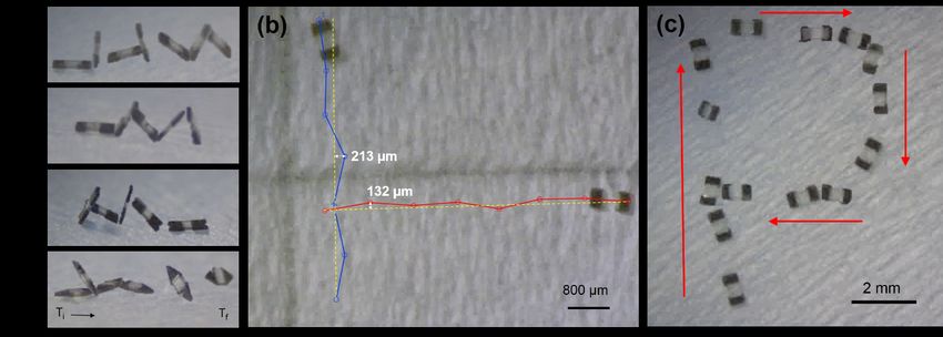
Micromachines 2018, 9, 68                                                                             3 of 17

motion along non-smooth surfaces. Lower magnetic field strengths are needed to drive the robot
due its tumbling locomotion mode. A second mode of operation (stick-slip) was also demonstrated
for these robots for use in manipulation tasks. However, both stick-slip and sliding motion are
difficult on non-planar geometries, such as bumps or trenches. Therefore, in this paper, we focus on a
microrobot design, fabrication and actuation strategy to overcome these complex terrains in both wet
and dry environments. We first introduce new microscale magnetic tumbling microrobots (µTUMs)
fabricated by a versatile microfabrication approach that permits us to define different rotational axes
and geometries of its magnetic ends for control with an external rotating magnetic field. The proposed
µTUM is then quantitatively analyzed with theoretical methods, considering the unique resistance
factors taking place at the microscale. µTUM prototypes with different particle alignment and motion
performance under rotational magnetic fields, as well as various geometries at their magnetic ends,
are tested to demonstrate the tumbling mechanism on the microscale in both wet (silicone oil, water)
and dry environments. They show an increased dynamic response to an actuating external rotating
magnetic field when compared to other rolling robots (i.e., RodBot). The optimal µTUM configuration
is later tested for its ability to climb different inclined planes and traverse complex terrains. Finally,
the paper is concluded with a discussion on present limitations and future work.

2. µTUM Robots

2.1. Design Overview
      The magnetic microscale tumbling robot (µTUM) presented in this paper is rectangular-shaped
with magnetic particles embedded in each of its two length-wise ends; see Figure 1. Permanent hard
magnetic bodies are implemented instead of soft magnetic bodies, such as nickel, due to their generally
higher magnetization values and their ability to be magnetically aligned in directions independent
of their geometry. The robot’s magnetic features are aligned along the same direction and behave
similarly under the presence of an external magnetic field. When the magnetic alignment of the field
differs from that of the robot, a magnetic torque is induced on the robot until it is realigned with the
field. Applying a continuously rotating magnetic field along a rotational axis parallel to the horizontal
plane causes the robot to rotate about the same axis. If this rotating field is applied on a robot that
is resting on a surface, the result is a forward tumbling motion, where the robot propels itself by
continuously flipping end-over-end.

     Figure 1. (a) Schematic of the microscale magnetic tumbling (µTUM) robot. The rectangular-shaped
     microrobot has embedded magnetic particles at each end. (b) Depending on the alignment of the
     magnetic particles, a rotating magnetic field will cause the µTUM to either lengthwise tumble (LT)
     or sideways tumble (ST). (c) Screen-shots from Supplemental Video S1 demonstrating both types of
     tumbling locomotion.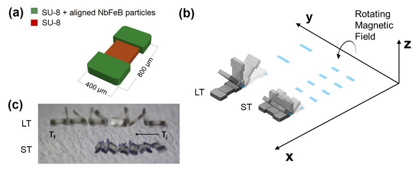
Micromachines 2018, 9, 68                                                                            4 of 17

      While a cylindrical form factor would result in a more predictable, precise rolling motion, such
geometry would also reduce the robot’s responsiveness and performance. To travel at the same
speed under a rotating magnetic field as a tumbling flat bar (rectangular) robot, assuming the robot
operates with no slip, a rolling cylindrical robot needs to have a diameter that is equal to the bar robot’s
length. In this case, the resultant cylindrical robot’s mass will be larger than that of the flat bar robot.
The increased mass leads to more weight, making it harder for the robot to climb inclined surfaces.
Additionally, curved three-dimensional geometry is difficult to fabricate at the microscale level using
traditional techniques, and prior research has largely focused on flat form factors for hard-magnet
micro-robots. For these reasons, a tumbling rectangular-shaped robot was chosen over a rolling robot
to tackle rough terrain and unpredictable environments.
      Flat, hard-magnet robots have been demonstrated in the past to operate in both dry and wet
conditions [19]. Unlike the µTUM, however, these robots use rocking (stick-slip) motion under an
alternating magnetic field, where contact between the robot and the surface is continually lost and
regained with each oscillation. Though the continuously rotating field used for the µTUM is harder
to implement than an alternating field, the trade-off is that the tumbling robot always has a point in
contact with the ground, provided that there are no sharp drop-offs or cliffs in its path. This sustained
contact means that the µTUM design can take advantage of the constant adhesion and frictional forces
between itself and the surface below it to climb steep inclined terrains. At the microscale, where the
effect of surface forces begins to surpass the effect of volumetric forces, the magnitude of these two
forces can often exceed that of gravitational force.
      Two distinct tumbling motions, a lengthwise tumbling (LT) motion and a sideways tumbling
(ST) motion (Figure 1b) can be observed depending on the direction of the µTUM’s internal magnetic
alignment. The robot’s hard magnet design allows its magnetic poles to be aligned along any direction,
so long as the fabrication method permits it. When the poles are aligned along one of the robot’s major
geometric axes, as defined in Figure 2, µTUM will either tumble about its length or tumble about its
width. Under the same external rotating field, a lengthwise tumbling µTUM will travel faster than a
sideways tumbling µTUM (see Supplementary Video S1). The former design, however, also requires
more force to raise up from a flat initial resting position, due to its longer lever arm. Since speed was
deemed to be more important for locomotive purposes, the lengthwise tumbling design was chosen
to be the primary configuration of µTUM. To determine the correct magnetic alignment for enabling
this type of tumbling motion, the equilibrium states of several µTUM alignment configurations were
analyzed. The robot’s initial position is defined in Figure 3, and all forces apart from magnetic torque
are ignored in this static analysis. It can be observed that there is only one configuration where the
robot consistently moves to the upwards lengthwise position necessary for lengthwise tumbling.
This case occurs when the robot is magnetically aligned along its x-axis and is influenced by a vertical
horizontal field. There is another configuration in which the upwards lengthwise position is seen
(Figure 3(ii)), but in this case, an upward sideways position (Figure 3(i)) is also possible under the
same field orientation. Because the sideways position is at a lower energy state than the lengthwise
position (due to the sideways position’s lower center of mass), this other configuration tends to result
in sideways tumbling. Pure lengthwise tumbling is only guaranteed in the former case, where the
robot is magnetically aligned along its geometric x-axis. As a result, the robots used for the majority of
the experiments are magnetically aligned in this manner and are optimized for lengthwise tumbling.
      Several other design variations of the geometries of the magnetic body sections were also
developed to explore how this geometry might affect its tumbling performance. The number of
corners, the sharpness of the corners and the protrusion of the corners were varied to see if the robot’s
performance would be significantly affected by any of these factors. The effect of symmetry was also
explored by fabricating robots with ends of slightly different lengths. For testing purposes, the rounded
rectangle geometry was chosen as the default design, due to its uniform flat edges and predictable
behavior, and the other designs were compared against it. For all the design configurations considered,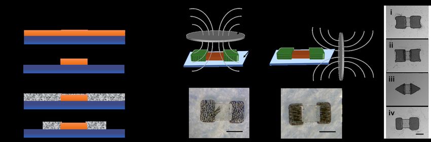
Micromachines 2018, 9, 68                                                                                   5 of 17

the mid-section of the robot was kept non-magnetized in order to explore the future possibility of
embedding a payload in this area of the robot.

            Figure 2. Visualization of internal magnetic alignment along the robot’s three major axes.

     Figure 3. Equilibrium resting states of each major axis alignment configuration under horizontal and
     vertical external magnetic fields. Note: for z-axis alignment, both (i) and (ii) are possible under the
     same conditions, but (i) is in a lower energy state than (ii) and thus more likely to occur in practice.

2.2. Modeling
      One of the first considerations for the tumbling robot is whether the driving external magnetic
field is strong enough to rotate it up from an initial resting position, where forces due to gravity,
electrostatic attraction and surface adhesion must be overcome. A static analysis of the forces on
the robot was conducted to determine the minimum external field strengths required for upwards
rotational movement. For modeling purposes, the various constituents of microscale surface adhesion,
such as intermolecular bonding, van der Waals interactions and capillary forces, are lumped together
into a single adhesive force Fa . The modeled robot’s magnetic alignment is assumed to be optimized
for lengthwise tumbling, and the external magnetic field is assumed to be uniform and time-invariant.
      When the internal magnetic alignment of the robot differs from that of the external field, a magnetic
torque is induced on the robot. This torque can be described as:

                                                ~Tm = Vm M
                                                         ~ × ~B                                                 (1)

where Vm is the magnetic volume of the robot, M    ~ is the magnetization of the robot and ~B is the magnetic
field strength, or flux density, of the external field. Though additional forces may act on the robot due
to magnetic field gradients, such forces are not considered in the model because no significant field
gradients were applied during experimentation. From Equation (1), it can be seen that the maximum
magnetic torque will occur when the robot and the external field alignments are perpendicular to each
other. Assuming that the robot is initially resting on a flat horizontal surface, this relationship indicates
that the external field should be vertically aligned to obtain the maximum possible magnetic torque
on the robot. Additional torque due to gravitational, electrostatic and adhesive forces counteract this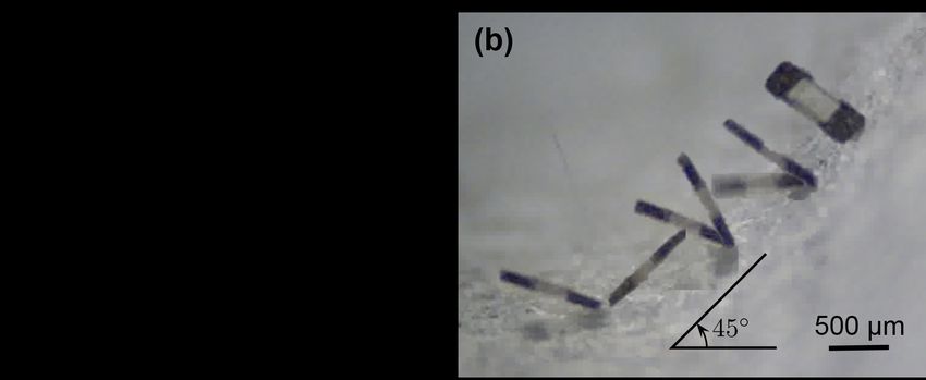
Micromachines 2018, 9, 68                                                                                     6 of 17

applied magnetic torque and hinder the robot from rotating upwards. When the magnetic torque is
kept static, all the torques balance out, and the robot comes to rest at an equilibrium angle. One end of
the robot will maintain contact with the surface while the other end rotates upward. The contacting
end of the robot can be considered as a no-slip point that is pinned to the surface. The resultant
side-view free-body diagram can be seen in Figure 4a.
     In practice, it is observed that the actual magnetic alignment of µTUM does not match the desired
magnetic alignment exactly, due to the alignment errors in the fabrication method used. An alignment
offset angle φ, defined as the angular difference between the robot’s actual alignment direction and the
desired alignment direction, is introduced in the model to account for this discrepancy. Due to varying
alignment offset angles, it is possible for different µTUM robots to stabilize at different equilibrium
orientations, despite having identical geometries, applied fields, material properties and operating
environments. Determining the alignment offset angle φ is critical because the robot will eventually
transition from the desired lengthwise tumbling motion to an undesired sideways tumbling motion as
φ increases from 0◦ –90◦ .

     Figure 4. (a) Force diagram: Point C is the center of mass and Point P is the contact point. Note that
     adhesion force will act on the center of mass if the robot is resting flat on the ground. (b) General plot
     of magnetic field strength versus robot orientation angle.

     Evaluating a moment equilibrium about the pinned contact point P in Figure 4a yields the
following equations:

                                                              L
                                 ΣMP = 0 = Tm − (mg + Felect ) cos(θ + α)                                         (2)
                                                              2

                                                                     L
                              Vm | M || B|cos(θ + φ) = (mg + Felect ) cos(θ + α)                                  (3)
                                                                     2

                                                 (mg + Felect ) L2 cos(θ + α)
                                        | B| =                                                                    (4)
                                                    Vm | M|cos(θ + φ)

                                                   (mg + Felect + Fa ) L2 cosα
                                      | Bmin | =                                                                  (5)
                                                        Vm | M |cosφ
where L is the length of the robot, θ is the equilibrium orientation angle of the robot, φ is the magnetic
alignment offset angle and α is the angle between the corner of the robot and its center of mass.
Fa and Felect are the adhesive and electrostatic forces respectively between the robot and the surface on
which it rests. Equation (4) is valid when the orientation angle θ of the robot is greater than 0◦ , and
Equation (5) is valid when the robot is flat against the surface and is just beginning to rise. The primary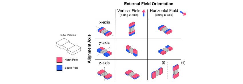
Micromachines 2018, 9, 68                                                                            7 of 17

difference between the two equations is that the latter equation contains an adhesion force term while
the former equation does not. This change is necessary because adhesion acts on the robot’s center
of mass instead of the pinned point P when the robot is resting flat on the surface. Together, the two
equations describe the relationship between the strength of the external magnetic field and the robot’s
resultant orientation, with Equation (5) approximating the minimum field strength required to raise
the robot up from the surface. Since the model only considers static equilibrium positions, the effects
of dynamic forces such as viscous drag are neglected.
     A simple measurement of when µTUM begins to slip on a surface of interest can be used to
determine the unknown electrostatic and adhesion forces in Equations (2)–(5). The robot is laid flat on
the horizontal surface, and the surface is then inclined until the robot begins sliding. At this point of
slippage, the force of the robot’s weight down the incline matches the force of static friction, and the
sum of the electrostatic and adhesive forces can be written as:

                                                    mgsinγ
                                    Fa + Felect =          − mgcosγ                                     (6)
                                                      µs
where angle γ is the surface inclination angle at which µTUM is observed to slip.
      To increase the usefulness of Equation (6), several assumptions can be made about the nature
of the electrostatic and adhesive forces. In dry environments, electrostatic force is significant for
non-conductive objects because there is no fluid to dissipate individual charges. The opposite is
true for fluid environments, where the presence of fluid makes the electrostatic force much smaller.
On rough surfaces, adhesive force is negligible because high surface roughness reduces the contact area
between the robot and the surface. The opposite is true for smooth surfaces, where adhesive force is
significant due to large contact areas. Therefore, the left side of Equation (6) can be reduced to just the
electrostatic force Felect in dry, rough environments, and it can be reduced to just the adhesive force Fa
in wet, smooth environments. An additional assumption is that the electrostatic force remains constant
regardless of the robot’s orientation. Though it is known that this force is proportional to the distance
between two objects, the change in distance between the surface and the robot as it rises is relatively
small in comparison to the electrostatic force’s overall area of effect. The result of these assumptions is
utilized in Section 4.1 to predict the robot’s orientation under varying external field strengths.
      To determine the unknown alignment offset angle φ in Equations (4) and (5), the maximum
equilibrium angle θ that is observed experimentally can be used. As the external field strength
increases, the robot asymptotically approaches a saturated maximum equilibrium angle. This behavior
is illustrated schematically in Figure 4b. The right side of Equation (3) becomes nearly constant at
higher field strengths, with the equilibrium angle θ approaching the constant saturation angle. In order
for the left side of Equation (3) to also remain constant as the field strength increases, the cosine term
must approach zero, and the following relationship can be derived:

                                             θmax = 90◦ − φ                                             (7)

     This relationship indicates that the offset angle φ can be determined by measuring the robot’s
maximum equilibrium orientation angle θmax . Such a measurement can be performed by placing
µTUM slightly above the center of a strong magnet, ideally where the magnet’s field is vertical, and
measuring the robot’s resultant orientation angle θ. This simple process allows the alignment offset
angle φ to be approximated without the need for complex measuring equipment. The angle can then
be used to predict µTUM performance using Equations (4) and (5) and evaluate the success of different
fabrication methods, where a smaller offset angle indicates less alignment error.

3. Fabrication
    The µTUM’s body is a polymeric-based microstructure consisting of (i) two sections with
embedded neodymium-iron-boron (NbFeB) particles at the ends and (ii) one non-magnetic bridge part
Micromachines 2018, 9, 68                                                                                  8 of 17

connecting them (Figure 5a). In order to obtain a better response to the magnetic fields, the NbFeB
particles are conveniently aligned during the fabrication process itself (Figure 5b). µTUM fabrications
are based on a simple and versatile two-step photolithography process, where the non-magnetic
middle section is first photo-patterned by using bare SU-8 50 (Microchem Inc., Westborough, MA,
USA) (Figure 5a, Steps 1 and 2), and the µTUM ends are then fabricated by SU-8 doped with NbFeB
particles (Magnequench MQFP 5 µm, Neo Magnequench, Toronto, Canada) with a concentration
of 10 gr/50 mL (Figure 5a, Steps 3 and 4). To pattern the middle polymeric section, the standard
recommended protocol for structures of 100 µm in thickness was followed (www.microchem.com).
The SU-8 50 is spin-coated at 1000 rpm for 30 s and then undergoes a soft baking process consisting of
two consecutive steps of 10 min at 65 ◦ C and 30 min at 95 ◦ C in order to evaporate the solvent. The full
wafer is then exposed in a mask aligner (UV (350–400 nm), Suss MA 6 Mask Aligner, SUSS MicroTec
AG, Garching near Munich, Germany) by using a mask with a design corresponding to the middle
section of the robot. A post-exposure bake (1 min at 65 ◦ C and 10 min at 95 ◦ C) is performed before the
removal of the non-polymerized SU-8 with SU-8 developer (Microchem Inc.).

     Figure 5. Fabrication process of microscale magnetic tumbling motors (µTUM). (a) Photolithography
     process followed for the the fabrication of µTUM. (b) Magnetic particle alignment techniques. Magnets
     located above the robot result in alignment along the geometric z-axis and sideways tumbling (ST);
     magnets located beside the robot result in alignment along the geometric x-axis and lengthwise
     tumbling (LT). (c) Optical images of the different geometric variations on the µTUM ending sections
     that have been explored: (i) rounded corners, (ii) sharp corners, (iii) triangles and (iv) (asymmetric)
     rounded rectangles. Scale bar, 300 µm.

     For the magnetic sections, the standard protocol was adjusted by including a pre-alignment step
during the soft curing process (Figure 5b). By placing two permanent magnetic discs (3 inches in dia.
× 1/8 inch-thick NdFeB, Grade N42, K & J Magnetics Inc., Plumsteadville, PA, USA) vertically next
to the wafer (Figure 5b), a µTUM alignment along its geometric x-axis was obtained, resulting in a
lengthwise tumbling (LT) motion (Figure 5b, right). However, when the same two magnets are located
above the silicon wafer during soft curing, the resultant robots yield a sideways tumbling (ST) motion
(Figure 5b, left). The type of tumbling motion that is observed in the finished robot is determined by
the position of the two magnetic discs during the fabrication process.
     Due to the flexibility of the fabrication method presented, where hard magnets can be formed out
of any two-dimensional shape, several different geometries for µTUM’s magnetic ends were explored.
Four types of geometries were considered in total: (i) rounded corners, (ii) sharp corners, (iii) triangles
and (iv) rounded rectangles (Figure 5c). For the rounded rectangles geometry, two different cases were
considered: a symmetric version (Figure 5b, right) and an asymmetric version (Figure 5c(iv)).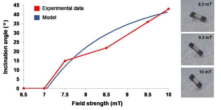
Micromachines 2018, 9, 68                                                                                   9 of 17

4. Experimental Results
      The driving external magnetic fields are generated by the MFG-100 system (MagnebotiX AG,
Zurich, Switzerland, magnebotix.com) as shown in Figure 6a. This system is capable of generating
up to a 40 mT field strength and field gradients of up to 2 T/m at the center of the workspace, which
is about 10 mm in diameter. The power unit of the field generator can supply up to 20 A currents
and uses eight coils at a time to generate the specified field or gradient in the workspace. Rotational
fields of frequencies up to 2000 Hz at 2 mT and 100 Hz at 8 mT can also be generated in the workspace.
The control software communicates with the electronics hardware to specify the field strength, gradient
and frequency of rotational fields in the workspace. This software can also control the yaw, roll
and pitch of the field’s rotational axis, which allows for the steering control of µTUMs. Real-time
imaging is captured by an overhead camera and a side camera aligned at 60° with the out of plane
axis. Complementary metal oxide semiconductor (CMOS) cameras (Basler puA1600-60uc, Basler AG,
Ahrensburg, Germany, baslerweb.com) along with microscope lenses (Edmund VZM 450i, Edmund
Optics, Barrington, NJ, USA www.edmundoptics.com) of adjustable magnification are used in both
the axes to record the motion of the robots.

     Figure 6. (a) The MFG-100 system with the top camera (1) and side camera (2). The paper surface
     inside a Petri dish at the center of the workspace. Top and side views of a µTUM as seen through the
     cameras. (b) Qualitative diagram of the various terrain geometries designed and fabricated: (i) inclined
     plane, (ii) cylindrical bumps, (iii) honeycomb and (iv) knurled.

      The default design of the µTUM robot (rounded rectangle geometry with alignment tuned for
lengthwise tumbling) was tested on a dry paper surface (Kimwipes, Kimtech Science, Kimberly-Clark
Corporation, Irving, TX, USA) in order to evaluate its performance under varying field rotation
frequencies and surface inclination angles. The external field strength was kept constant at 10 mT for
all dynamic experiments. A paper surface within a dry environment was used for the majority of the
characterization tests due to its challenging nature, where beneficial damping and buoyancy forces are
minimal and friction forces are high. Additional performance tests were conducted in both water and
silicone oil to gauge and characterize robot capabilities in fluid environments of varying viscosity.
      Much like the geometric variants of µTUM, several terrain geometries were also developed to see
if the presence of curved surfaces, small inclined surfaces and holes in the terrain would significantly
affect the robot’s performance (Figure 6b). These terrain geometries include a pattern with cylindrical
Micromachines 2018, 9, 68 10 of 17
bumps, a honeycomb pattern and a knurled pattern. They were fabricated using a Form 1+ SLA 3D
printer from Form Labs (www.formlabs.com).
4.1. Static Analysis Tests
To test the validity of the static model discussed in Section 2.2, the µTUM’s orientation under
varying external field strengths was predicted and then juxtaposed alongside experimental data. For a
rough paper surface within a dry environment, the parameters listed in Table 1 apply. Due to the
reasoning detailed in Section 2.2, electrostatic force is assumed to be constant and adhesive force is
assumed to be negligible. The saturated equilibrium angle θmax was measured to be 63◦ , indicating that
the magnetic alignment offset angle φ is 27◦ . Additionally, the robot was observed to begin slipping on
the paper at a surface inclination angle of 70◦ , indicating an electrostatic force of Felect ≈ 5.48 × 10⁻⁶ N.
Table 1. Static inclination angle model parameters. The density of SU-8 (1190 g/m3 ) and NdFeB
(7500 g/m3 ) were used to calculate mass.
Description Value Units
µTUM Length (L) 0.8 × 10⁻³ m
Mass (m) 1.6071 × 10⁻⁷ kg
Electrostatic Force (Felect ) 5.4775 × 10⁻⁶ N
Static Friction Coefficient (µs ) 0.3 -
Geometric Offset Angle (α) 14.063 ◦
Magnetic Alignment Offset Angle (φ) 27 ◦
Magnetic Volume (Vm ) 2.9 × 10⁻¹¹ m3
Magnetization (M) 15,000 A/m
Under a static vertical magnetic field, the robot’s equilibrium orientation angle θ was recorded for
field strengths varying from 0–10 mT (Figure 7). The experimental angles closely matched those that
were predicted by the model, and a similar minimum field strength of roughly 7 mT was required to
raise the robot from its initial position.
Figure 7. Model and experimental equilibrium orientation angle θ at varying field strengths (Results
also shown in Supplemental Video S1).
4.2. Tumbling Locomotion Tests
The different geometric variants of the µTUMs were tested for their tumbling locomotion
capabilities along the same paper surface in dry environmental conditions (Figure 8a). No significant
differences were observed for robots with the rounded corners design and robots with the asymmetric
variant of the default rounded rectangle design. However, the rounded corners robots were observedMicromachines 2018, 9, 68 11 of 17
to be slightly faster than the default robots due to their longer length. Robots with the sharp corners
design were also observed to be slightly faster than the default robots, but their corners had a tendency
to hook into the fibers of the paper substrate. While this hooking action may potentially be beneficial
for climbing steep inclines, it is often detrimental and causes the robots to remain anchored to a
particular spot. Robots with the triangle design were observed to be vertically unstable and frequently
tilted over to their side. This behavior likely occurred because their centers of mass were not perfectly
aligned with their endpoints. The result is that robots with the triangle µTUM design cannot maintain
a stable tumbling motion and move forward in an erratic manner.
To assess the open-loop trajectory accuracy of the µTUM, the default rounded rectangular version
was commanded to translate along a 5 mm-long straight line path in both the vertical and horizontal
directions. Figure 8b shows these open-loop trajectories. The maximum deviations from the straight
line paths were 213 µm and 132 µm for the vertical and horizontal tests, respectively.
The µTUM with the default rounded rectangle design was also demonstrated to be steerable along
a desired trajectory. Manually adjusting the pitch and the yaw of the external field’s rotational axis in
increments of 90◦ allowed the robot to travel in a roughly P-shaped trajectory (Figure 8c). The input
was open-loop, and no closed-loop control was implemented.
Figure 8. µTUM locomotion tests: flat paper substrate, dry environment, with 10 mT field strength
at 0.5 Hz. (a) Images of trials for µTUM’s with different end variations: (1) rounded rectangle,
(2) asymmetric rounded rectangle, (3) rounded corners and (4) triangle shape. (b) Trajectories (blue/red)
of µTUM with respect to an ideal 5 mm-long straight line trajectory (yellow); the maximum trajectory
drift for each is reported. (c) Default rounded rectangle µTUM design traversing the P-shaped trajectory.
These results can be viewed in Supplemental Video S2.
Figure 9 plots the average translational speed of a default µTUM robot under varying field
rotational frequencies for a variety of environmental conditions. It can be seen that the translational
speed of the robot in dry air on paper increases roughly linearly as the rotational frequency of the
external field increases. The robot was observed to be tumbling without slipping in this case. It follows
that the robot’s average translational speed v̄ should be approximately equal to four-times the body
length (L) multiplied by the field rotational frequency f rot :
v̄no slip = 4L f rot (8)
since the robot tumbles over its length twice when the magnetic field completes one full rotation.
At higher field rotational frequencies, it can be seen that the experimental speeds are slightly higher
than the predicted speeds. This discrepancy is likely because higher rotational frequencies can
produce undesired magnetic field gradients in the MagnebotiX machine, which will apply a pulling
force on the robot. A maximum translational speed of 58.1 mm/s was measured, but the upwards
trend in Figure 9 suggests that the speed of µTUM will continue to increase as the external field’sMicromachines 2018, 9, 68 12 of 17
rotational frequency increases above 15 Hz. On a substrate within a water environment, the presence of
buoyancy forces leads to lower frictional forces, since friction is proportional to the total normal force.
This reduced friction causes µTUM to slip on the substrate, and the resultant relationship between the
robot’s translational speed and the field rotational frequency fails to follow a linear curve. At higher
frequencies, the translational speed of the robot becomes noticeably saturated at 13.6 mm/s. On a
substrate within a silicone oil environment, higher viscosity and larger drag forces lead to phase
lag between the orientation of the robot and the orientation of the external magnetic field. As the
external field’s rotational frequency increases, the larger drag forces prevent the µTUM from keeping
up, and the robot begins oscillating in place instead of tumbling forward. This behavior occurs at field
rotational frequencies of 2 Hz and above. Higher buoyancy forces in silicone oil result in even more
slip, and the average translational speeds in this medium are much lower than in the others, with the
maximum translational speed measured in silicone oil being 0.975 mm/s.
Figure 9. Experimental and modeled average translational speed under varying field rotational
frequencies for various conditions. Results also shown in Supplemental Video S3.
4.3. Inclined Plane Traversal Tests
Tests to determine if the default design µTUM can traverse an incline at various angles were
performed and evaluated on a pass/fail basis. The results are reported in Figure 10a. The dry air
incline tests received more focus because the lack of beneficial buoyancy forces and the significant
presence of electrostatic forces make the climb significantly harder. It was observed that the robot can
go over a maximum inclination of 45◦ in dry conditions on paper. Due to the additional buoyancy
force and dissipation of electrostatic charges in the denser liquid mediums, the robot was shown to
be capable of climbing inclines of at least 60◦ in water and silicone oil. The possibility that the robot
could be swimming was ruled out after it was observed that the robot did not move forward after
losing contact with the surface (see Supplementary Video S3). Figure 10b shows images of the µTUM
climbing up a 45◦ angle in dry conditions. It does not slip on the terrain in dry conditions until it
reaches an incline angle that it cannot traverse. When µTUM climbs inclines in either water or silicone
oil, however, it tends to roll and slip along the incline, traveling at reduced overall speed.Micromachines 2018, 9, 68 13 of 17
Figure 10. Inclined plane traversal tests. (a) Table of results for different inclination angles and
environments; (b) images of the µTUM traversing a 45◦ angle in dry conditions (10 mT field @ 0.5 Hz).
Please see Supplemental Video S4 for video footage of these tests.
4.4. Complex Terrain Tests
Figure 11 presents the µTUM’s performance over various complex terrains. Tests were conducted
on a flat paper surface and three 3D printed complex terrains, all in dry conditions. Figure 11a details
the dimensions of each of the terrain features. Performance over the three complex terrains was similar,
with mean velocities slightly slower than that of the flat surface. This can be attributed to the fact that
the complex terrain surfaces bump or tilt the robot off to the side during the course of travel, as well as
the difference in surface material.
Figure 11. (a) Dimensions of the terrain geometries explored (all dimensions in millimeters); (b) µTUM
traveling over different terrains in dry environments, with a 10 mT field strength @ 0.5 Hz. (i) Flat
paper; (ii) cylindrical bumps; (ii) knurled surface; (iv) honeycomb terrain (side-ways tumbling mode).
Please see Supplemental Video S5 for video footage of these tests.Micromachines 2018, 9, 68 14 of 17
Utilizing the default lengthwise tumbling mode, µTUM was able to travel over the knurled and
cylindrical bump terrains seen in Figure 11b(ii,iii), respectively. However, it had difficulty getting up
from its initial resting position on the honeycomb terrain. It is believed that concave pores, such as
the honeycomb holes, increase the adhesive force between the robot and the surface when they are
roughly the size of the robot’s cross-sectional area. After switching the default µTUM robot with a
µTUM configured for sideways tumbling, the honeycomb terrain became much easier to traverse,
as seen in Figure 11b(iv). With a smaller lever arm to rotate, the magnetic torque required to break
the attractive surface forces decreased. The sideways tumbling µTUM variant, as a result, was able to
traverse through honeycomb terrain under the same magnetic field strength and rotational frequency
that the default design could not.
5. Discussion and Conclusions
The µTUM microrobot was able to exhibit tumbling movement through three different mediums
under varying external field and surface conditions. As these environmental parameters were changed,
several trends were observed. Increasing the drag coefficient of the surrounding environment limited
the maximum field rotational frequency that the robot could follow. The dampened speeds observed
in high-drag environments, however, also made the robot easier to observe and control. Increasing
the density of the surrounding environment lowered the minimum field strength required to rotate
the robot upwards from an initial resting position, due to larger buoyancy force. The reduced normal
force between the robot and the surface, however, also reduced friction force and made the robot
more prone to slipping. In contrast, increased attractive forces between the robot and substrate raise
the minimum field strength required for initial upwards rotation and make the robot less prone to
slipping. In dry environments, the drag and buoyancy forces are both negligible, and high tumbling
speeds can be obtained. This advantage occurs at the cost of high external field strength requirements,
due to the presence of electrostatic attraction between the robot and the substrate. The opposite
behavior is observed in wet environments, where the drag and buoyancy forces are both significant
and electrostatic charges are dissipated into the fluid. The various trends that occur as the µTUM
traverses through different environments presents challenges in closed-loop control and optimal
pathfinding that will need to be addressed in the future.
The experiments demonstrate that highly viscous fluids, such as silicone oil, impose limitations on
the robot’s maximum rotational frequency, and low density mediums, such as air, impose limitations on
the steepest incline that can be traversed. Minimizing slip, weight and the effect of electrostatic charges
is crucial for reducing the effect of these limitations and optimizing traversal through multiple terrains.
There is a need to minimize the slip experienced by the outer edges of the robot while simultaneously
avoiding the hooking action observed in robots with sharp corners. There is also a need to reduce
the adhesive force on the main body of the robot. Options for making such improvements include
increasing the surface roughness of the µTUM, increasing the contact area of its outer edges and
decreasing the contact area of the robot’s main body.
Of the four different types of robot geometries fabricated, the rounded corners and rounded
rectangle designs were the most effective at maintaining consistent forward movement. Excessively sharp
corners were found to increase the likelihood of the robot hooking into rough surfaces and getting
stuck. Decreasing the number of corners reduced vertical stability in dry conditions and tumbling
motion could not be achieved for triangular end geometries. From the three different complex
terrains fabricated, it was observed that small concave surface features adversely affected the robot’s
performance by increasing the adhesion force between the robot and the substrate.
Difficulties were encountered in measurements and modeling due to the anisotropic nature of
adhesion and frictional forces on rough surfaces at the micro-scale. µTUM performance can vary
significantly depending on the material properties of initial starting point. In the future, higher input
field strengths can be used and magnetic particles with higher magnetization can be incorporated
to reduce the overall effect of these forces. Low yield rates were also observed during fabricationMicromachines 2018, 9, 68 15 of 17
due to the nature of the alignment magnets used. The field lines emanating from its poles are spread
out and not necessarily oriented in the desired direction. A Helmholtz coil can be used instead of
simple permanent magnets to generate nearly parallel alignment lines. In the meantime, the technique
developed in Section 2.2 allows the alignment offset angle to be easily measured and used to determine
the minimum field strength required for tumbling movement.
Future work will focus on dynamic modeling of the µTUM that can predict its motion trajectories
over complex terrains, as well as addressing the unique challenges present at the interface of distinct
environments. Capillary forces found in air-water interfaces, for example, can induce significant lateral
forces on the robot that need to be considered [42]. Additional goals include developing vision-based
closed-loop control for precisely navigating the robot to a desired destination and also revisiting the
new µTUM design for micromanipulation tasks. Alternate designs for the mid-section of the robot,
kept non-magnetized in this work, will be explored, as well. Replacing this area with a compliant
material or a dissolvable payload could lead to improved dynamic behavior and in vivo drug delivery,
respectively, with far-reaching potential in micro-object manipulation and biomedical applications.
Supplementary Materials: The following are available online at www.mdpi.com/2072-666X/9/2/68/s6:
Supplemental Video S1: µTUM lengthwise and sideways tumbling modes and inclination angle tests; Video S2:
µTUM locomotion tests; Video S3: µTUM locomotion in different environmental conditions; Video S4: µTUM
inclined plane traversal tests; and Video S5: µTUM traveling over different terrains.
Acknowledgments: This work was supported by NSF IISAward 1149827. The authors acknowledge the facility
access at Birck Nanotechnology Center (Purdue University), Sagar Chowdhury and Lamar Mair for their support
and valuable discussions for the theoretical simulations and Jesse Roll for 3D printing of the terrains.
Author Contributions: C.B., M.G. and D.J.C.conceived of and designed the experiments. C.B. and M.G. performed
the experiments and analyzed the corresponding data. C.B., B.V.J. developed the theoretical models. C.B., M.G.,
B.V.J., W.J. and D.J.C. wrote the paper.
Conflicts of Interest: The authors declare no conflict of interest.
References
1. Purcell, E. Life at low Reynolds number. Am. J. Phys. 1977, 45, 3–11.
2. Sitti, M. Mobile Microrobotics; The MIT Press: Cambridge, MA, USA, 2017.
3. Guix, M.; Mayorga-Martinez, C.C.; Merkoçi, A. Nano/micromotors in (bio)chemical science applications.
Chem. Rev. 2014, 114, 6285–6322.
4. Parmar, J.; Ma, X.; Katuri, J.; Simmchen, J.; Stanton, M.M.; Trichet-Paredes, C.; Soler, L.; Sanchez, S. Nano
and micro architectures for self-propelled motors. Sci. Technol. Adv. Mater. 2015, 16, 014802.
5. Li, J.; Esteban-Fernández de Ávila, B.; Gao, W.; Zhang, L.; Wang, J. Micro/nanorobots for biomedicine:
Delivery, surgery, sensing, and detoxification. Sci. Robot. 2017, 2, eaam6431.
6. Donald, B.R.; Levey, C.G.; McGray, C.G.; Paprotny, I.; Rus, D. An untethered, electrostatic, globally
controllable MEMS micro-robot. J. Microelectromech. Syst. 2006, 15, 1–15.
7. Sul, O.J.; Falvo, M.R.; Taylor, R.M.; Washburn, S.; Superfine, R. Thermally actuated untethered impact-driven
locomotive microdevices. Appl. Phys. Lett. 2006, 89, 1–4.
8. Gao, W.; Wang, J. Synthetic micro/nanomotors in drug delivery. Nanoscale 2014, 6, 10486–10494.
9. Sitti, M.; Ceylan, H.; Hu, W.; Giltinan, J.; Turan, M.; Yim, S.; Diller, E. Biomedical applications of untethered
mobile milli/microrobots. Proc. IEEE 2015, 103, 205–224.
10. Chen, X.Z.; Hoop, M.; Mushtaq, F.; Siringil, E.; Hu, C.; Nelson, B.J.; Pané, S. Recent developments in
magnetically driven micro- and nanorobots. Appl. Mater. Today 2017, 9, 37–48.
11. Abbott, J.J.; Ergeneman, O.; Kummer, M.P.; Hirt, A.M.; Nelson, B.J. Modeling magnetic torque and force for
controlled manipulation of soft-magnetic bodies. IEEE Trans. Robot. 2007, 23, 1247–1252.
12. Kummer, M.P.; Abbott, J.J.; Kratochvil, B.E.; Borer, R.; Sengul, A.; Nelson, B.J. Octomag: An electromagnetic
system for 5-DOF wireless micromanipulation. IEEE Trans. Robot. 2010, 26, 1006–1017.
13. Bouchebout, S.; Bolopion, A.; Abrahamians, J.O.; Régnier, S. An overview of multiple DoF magnetic actuated
micro-robots. J. Micro-Nano Mechatron. 2012, 7, 97–113.Micromachines 2018, 9, 68 16 of 17
14. Vonthron, M.; Lalande, V.; Bringout, G.; Tremblay, C.; Martel, S. A MRI-based integrated platform for
the navigation of microdevices and microrobots. In Proceedings of the IEEE International Conference on
Intelligent Robots and Systems, San Francisco, CA, USA, 25–30 September 2011; pp. 1285–1290.
15. Tabatabaei, S.N.; Lapointe, J.; Martel, S. Shrinkable hydrogel-based magnetic microrobots for interventions
in the vascular network. Adv. Robot. 2011, 25, 1049–1067.
16. Pawashe, C.; Floyd, S.; Sitti, M. Modeling and experimental characterization of an untethered magnetic
micro-robot. Int. J. Robot. Res. 2009, 28, 1077–1094.
17. Diller, E.; Floyd, S.; Pawashe, C.; Sitti, M. Control of multiple heterogeneous magnetic micro-robots on
non-specialized surfaces. In Proceedings of the IEEE International Conference on Robotics and Automation,
Shanghai, China, 9–13 May 2011; Volume 28, pp. 115–120.
18. Pawashe, C.; Floyd, S.; Diller, E.; Sitti, M. Two-dimensional autonomous microparticle manipulation
strategies for magnetic microrobots in fluidic environments. IEEE Trans. Robot. 2012, 28, 467–477.
19. Floyd, S.; Pawashe, C.; Sitti, M. An untethered magnetically actuated micro-robot capable of motion
on arbitrary surfaces. In Proceedings of the IEEE International Conference on Robotics and Automation,
Pasadena, CA, USA, 19–23 May 2008; pp. 419–424.
20. Huang, H.W.; Sakar, M.S.; Petruska, A.J.; Pané, S.; Nelson, B.J. Soft micromachines with programmable
motility and morphology. Nat. Commun. 2016, 7, 12263.
21. Medina-Sánchez, M.; Schwarz, L.; Meyer, A.K.; Hebenstreit, F.; Schmidt, O.G. Cellular cargo delivery:
Toward assisted fertilization by sperm-carrying micromotors. Nano Lett. 2016, 16, 555–561.
22. Hou, M.T.; Shen, H.M.; Jiang, G.L.; Lu, C.N.; Hsu, I.J.; Yeh, J.A. A rolling locomotion method for untethered
magnetic microrobots. Appl. Phys. Lett. 2010, 96, 94–97.
23. Jiang, G.L.; Guu, Y.H.; Lu, C.N.; Li, P.K.; Shen, H.M.; Lee, L.S.; Yeh, J.A.; Hou, M.T.K. Development of rolling
magnetic Microrobots. J. Micromech. Microeng. 2010, 20, 085042.
24. Tung, H.W.; Peyer, K.E.; Sargent, D.F.; Nelson, B.J. Noncontact manipulation using a transversely magnetized
rolling robot. Appl. Phys. Lett. 2013, 103, 114101.
25. Pieters, R.; Tung, H.W.; Charreyron, S.; Sargent, D.F.; Nelson, B.J. RodBot: A rolling microrobot for
micromanipulation. In Proceedings of the IEEE International Conference on Robotics and Automation,
Seattle, WA, USA, 26–30 May 2015; pp. 4042–4047.
26. Kim, S.; Lee, S.; Lee, J.; Nelson, B.J.; Zhang, L.; Choi, H. Fabrication and manipulation of ciliary microrobots
with non-reciprocal magnetic actuation. Sci. Rep. 2016, 6, 1–9.
27. Vollmers, K.; Frutiger, D.R.; Kratochvil, B.E.; Nelson, B.J. Wireless resonant magnetic microactuator for
untethered mobile microrobots. Appl. Phys. Lett. 2008, 92, 144101–144104.
28. Frutiger, D.R.; Vollmers, K.; Kratochvil, B.E.; Nelson, B.J. Small, fast, and under control: Wireless resonant
magnetic micro-agents. Springer Tracts Adv. Robot. 2009, 54, 169–178.
29. Frutiger, D.R.; Kratochvil, B.E.; Nelson, B.J. MagMites—Microrobots for wireless microhandling in dry
and wet environments. In Proceedings of the IEEE International Conference on Robotics and Automation,
Anchorage, AK, USA, 3–7 May 2010; pp. 1112–1113.
30. Tung, H.W.; Maffioli, M.; Frutiger, D.R.; Sivaraman, K.M.; Pane, S.; Nelson, B.J. Polymer-based wireless
resonant magnetic microrobots. IEEE Trans. Robot. 2014, 30, 26–32.
31. Li, T.; Li, J.; Morozov, K.I.; Wu, Z.; Xu, T.; Rozen, I.; Leshansky, A.M.; Li, L.; Wang, J. Highly efficient freestyle
magnetic nanoswimmer. Nano Lett. 2017, 17, 5092–5098.
32. Li, J.; Li, T.; Xu, T.; Kiristi, M.; Liu, W.; Wu, Z.; Wang, J. Magneto-acoustic hybrid nanomotor. Nano Lett.
2015, 15, 4814–4821.
33. Diller, E. Micro-scale mobile robotics. Found. Trends Robot. 2011, 2, 143–259.
34. Khalil, I.S.M.; Magdanz, V.; Sanchez, S.; Schmidt, O.G.; Misra, S. Wireless magnetic-based closed-loop
control of self-propelled microjets. PLoS ONE 2014, 9, 3–8.
35. Guix, M.; An, Z.; Wang, J.; Johnson, B.V.; Cappelleri, D.J. Vision-based micro-force sensing mobile microrobots for
intelligent micromanipulation. In Proceedings of the IEEE International Conference on Robotics, Manipulation,
and Automation at Small Scales (MARSS), Montreal, QC, Canada, 17–21 July 2017.
36. Cappelleri, D.; Efthymiou, D.; Goswami, A.; Vitoroulis, N.; Zavlanos, M. Towards mobile microrobot swarms
for additive micromanufacturing. Int. J. Adv. Robot. Syst. 2014, 11, 150.
37. Diller, E.; Giltinan, J.; Sitti, M. Independent control of multiple magnetic microrobots in three dimensions.
Int. J. Robot. Res. 2013, 32, 614–631.Micromachines 2018, 9, 68 17 of 17
38. Chowdhury, S. Path planning and control for autonomous navigation of single and multiple magnetic
mobile microrobots. In Proceedings of the ASME 2015 International Design Engineering Technical
Conferences & Computers and Information in Engineering Conference, Boston, MA, USA, 2–5 August 2015;
pp. 1–10.
39. Chowdhury, S.; Jing, W.; Cappelleri, D.J. Controlling multiple microrobots: recent progress and future
challenges. J. Micro-Bio Robot. 2015, 10, 1–11.
40. Jing, W.; Pagano, N.; Cappelleri, D.J. A novel micro-scale magnetic tumbling microrobot. J. Micro-Bio Robot.
2013, 8, 1–12.
41. Jing, W.; Pagano, N.; Cappelleri, D.J. A tumbling magnetic microrobot with flexible operating modes.
In Proceedings of the IEEE International Conference on Robotics and Automation, Karlsruhe, Germany,
6–10 May 2013; pp. 5514–5519.
42. Wang, P.; Lu, H.; Shen, S.; Shang, W.; Zhang, L.; Wang, J.; Shen, Y. Microrobotic manipulation at time-varying
air-liquid interface for high-precise watch-hand alignment. IEEE/ASME Trans. Mechatron. 2017, 22,
2746–2756.
© 2018 by the authors. Licensee MDPI, Basel, Switzerland. This article is an open access
article distributed under the terms and conditions of the Creative Commons Attribution
(CC BY) license (http://creativecommons.org/licenses/by/4.0/).You can also read