Evaluation and Validation of Thorax Model Responses: A Hierarchical Approach to Achieve High Biofidelity for Thoracic Musculoskeletal System ...
←
→
Page content transcription
If your browser does not render page correctly, please read the page content below
ORIGINAL RESEARCH
                                                                                                                                                   published: 16 July 2021
                                                                                                                                          doi: 10.3389/fbioe.2021.712656

                                            Evaluation and Validation of Thorax
                                            Model Responses: A Hierarchical
                                            Approach to Achieve High Biofidelity
                                            for Thoracic Musculoskeletal System
                                            Wei Zeng, Sayak Mukherjee, Adrian Caudillo, Jason Forman and Matthew B. Panzer*
                                            Center for Applied Biomechanics, University of Virginia, Charlottesville, VA, United States

                                            As one of the most frequently occurring injuries, thoracic trauma is a significant public
                                            health burden occurring in road traffic crashes, sports accidents, and military events.
                                            The biomechanics of the human thorax under impact loading can be investigated by
                                            computational finite element (FE) models, which are capable of predicting complex
                                            thoracic responses and injury outcomes quantitatively. One of the key challenges for
                                            developing a biofidelic FE model involves model evaluation and validation. In this work,
                          Edited by:
           Alexandros E. Tsouknidas,
                                            the biofidelity of a mid-sized male thorax model has been evaluated and enhanced
    University of Western Macedonia,        by a multi-level, hierarchical strategy of validation, focusing on injury characteristics,
                             Greece
                                            and model improvement of the thoracic musculoskeletal system. At the component
                       Reviewed by:
                                            level, the biomechanical responses of several major thoracic load-bearing structures
                         Erin Mannen,
 Boise State University, United States      were validated against different relevant experimental cases in the literature, including
                        Diane Wagner,       the thoracic intervertebral joints, costovertebral joints, clavicle, sternum, and costal
 Indiana University-Purdue University
          Indianapolis, United States
                                            cartilages. As an example, the thoracic spine was improved by accurate representation
                  *Correspondence:
                                            of the components, material properties, and ligament failure features at tissue level
                   Matthew B. Panzer        then validated based on the quasi-static response at the segment level, flexion
                  panzer@virginia.edu
                                            bending response at the functional spinal unit level, and extension angle of the whole
                    Specialty section:
                                            thoracic spine. At ribcage and full thorax levels, the thorax model with validated bony
         This article was submitted to      components was evaluated by a series of experimental testing cases. The validation
                        Biomechanics,
                                            responses were rated above 0.76, as assessed by the CORA evaluation system,
                a section of the journal
       Frontiers in Bioengineering and      indicating the model exhibited overall good biofidelity. At both component and full thorax
                        Biotechnology       levels, the model showed good computational stability, and reasonable agreement
             Received: 20 May 2021          with the experimental data both qualitatively and quantitatively. It is expected that
            Accepted: 28 June 2021
            Published: 16 July 2021
                                            our validated thorax model can predict thorax behavior with high biofidelity to assess
                             Citation:
                                            injury risk and investigate injury mechanisms of the thoracic musculoskeletal system in
    Zeng W, Mukherjee S, Caudillo A,        various impact scenarios. The relevant validation cases established in this study shall be
     Forman J and Panzer MB (2021)
                                            directly used for future evaluation of other thorax models, and the validation approach
   Evaluation and Validation of Thorax
     Model Responses: A Hierarchical        and process presented here may provide an insightful framework toward multi-level
 Approach to Achieve High Biofidelity       validating of human body models.
for Thoracic Musculoskeletal System.
Front. Bioeng. Biotechnol. 9:712656.        Keywords: injury biomechanics, musculoskeletal system, finite element method, thorax model, validation,
     doi: 10.3389/fbioe.2021.712656         biofidelity, thoracic spine

Frontiers in Bioengineering and Biotechnology | www.frontiersin.org                 1                                                July 2021 | Volume 9 | Article 712656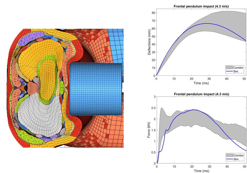
Zeng et al.                                                                                                   Thorax Model Evaluation and Validation

INTRODUCTION                                                                risks under various impact loads. Ensuring the biofidelity of
                                                                            these FE models, particularly for the thoracic MSK system,
The human thorax is a fairly complex body region with                       is indispensable for the credibility and utility of the tool for
musculoskeletal structures (ribcage) and soft tissue organs in              predicting injury to the ribcage and the intrathoracic tissues
the thoracic cavity. The ribcage consists of 12 thoracic vertebrae          and organs. In general, one of the major limitations of most
(T1–T12), 12 pairs of ribs, costal cartilages, sternum, scapulae,           of these thorax models was the lack of reasonable validations,
and clavicles. In automobile crashes, thoracic injury is one of the         mainly due to a significant paucity of available experimental data
most prevalent injuries, and ranks second only to head injury               at multi-levels. For example, if a thorax model was validated
with reference to the number of fatalities and serious injury               under a specific impact condition, its kinematics and injuries
outcomes (Forman et al., 2019). According to the Abbreviated                might not be valid under different impact loads. Even if the
Injury Scale (AIS), an anatomically based injury severity scoring           model was globally validated, it is uncertain if it has the
system, the musculoskeletal (MSK) injury accounted for the                  capability of predicting thoracic responses and injury risk at
highest percentage of thoracic AIS in all passenger vehicle                 a localized level. Additionally, the tissue material parameters
occupants (Cavanaugh and Yoganandan, 2015). The thoracic                    are not always available, and most of the experimental datasets
MSK system protects intrathoracic structures from external                  at the component or organ level were not prepared for the
penetration or blunt trauma, which is the leading cause of                  purposes of numerical simulations and model validation. As
injury during motor vehicle collisions (MVC). Biomechanically,              such, HBMs have been developed by the Global Human Body
the external force under blunt impact is mostly sustained by                Models Consortium (GHBMC), which is a multi-institution
the bony skeleton of the thorax, and the impact energy can                  collaboration involving industry, government, and academic
be dissipated by muscles and soft organs with viscoelasticity               researchers aiming to develop the most biofidelic computational
properties. A better understanding of the thorax biomechanics,              HBMs for crash safety advancement. Although the GHBMC
especially the biomechanical response and injury mechanisms                 models contain a significant amount of anatomical details
of thoracic MSK, is crucial to prevention and mitigation of                 and can provide a basis for further model development and
thorax injuries.                                                            applications, the thoracic region in the detailed GHBMC mid-
   To investigate MVC related human injuries and enhance                    sized male occupant FE model (M50-O) v4.5 model (released
vehicle safety designs, surrogates of occupants have been                   in 2018, the base model used for this study) has inadequacies
used, including post mortem human surrogates (PMHSs),                       and limitations, particularly in some important structures of the
anthropomorphic test devices (ATDs), and volunteers. They each              MSK system. These limitations could be attributed to model
have their strengths and limitations, but their common feature              simplifications or a lack of material verification, which requires
is that they provide a similar response to that of the living               further enhancement to increase accuracy and model biofidelity.
human body during a crash and are studied to assess MVC                        The goal of this study was to report on the hierarchical
injuries and develop or improve design for automotive safety                improvement, evaluation, and validation of the GHBMC M50
systems (Beeman et al., 2012). Over the past three decades,                 thorax model, focusing on the biofidelity of the thoracic
computational finite element (FE) human body models (HBMs)                  MSK system at multi-levels. Specifically, this study focuses on
have emerged as a powerful and versatile tool that can accurately           improvements and validations to the thoracic spine, clavicle,
describe the human anatomy, biomechanics, and variability for               sternum, costal cartilage, etc. To our knowledge, FE models for
injury risk predictions and vehicle safety systems development.             thoracic spine (T-spine) are fewer compared to cervical and
Compared to surrogates for safety designs, computational thorax             lumbar spines. Detailed T-spine models with proper verifications
FE models can integrate and represent thoracic biomechanical                and validations (V&V) using experimental studies are relatively
data from PMHS or volunteers, as well as efficiently evaluate both          rare, especially for impact scenarios. Aira et al. (2019) developed
overall thoracic responses and localized physical variables related         and validated a simplistic T-spine model using quasi-static
to injuries. For example, FE models can quantitatively predict              loading for adjacent vertebrae and rear hub impact for chest
complex chest deformation and bone fracture patterns that are               force-deflection response. However, it did not include the state-
not able to be evaluated via ATDs (Pipkorn and Kent, 2011).                 of-the-art modeling techniques and injury-predictive capabilities
   A considerable number of thorax FE models have been                      that have been used in C-spines models (Panzer et al., 2011).
developed to simulate chest behaviors under complex kinematics              This study builds on these previous efforts to enhance the
during various impact loading conditions. Yang et al. (2006)                existing GHBMC T-spine model with improved biofidelity,
reviewed thorax FE models published before 2005 and after                   additional validations, and injury simulation capability. The
2005 (Yang, 2018). These models were either isolated thorax                 enhanced model was validated against several experimental
models (Deng et al., 1999; Shen et al., 2008) or integrated                 cases at segment, functional spinal unit (FSU) and full torso
into full body model (FBM) (Robin, 2001; Haug et al., 2004;                 levels. The T-spine was incorporated into the thorax model,
Kimpara et al., 2005; Song et al., 2009; El-Jawahri et al., 2010;           and it was able to predict the soft tissue deformation and
Pipkorn and Kent, 2011; Antona-Makoshi et al., 2015; Iwamoto                ligament injury response under traumatic loading levels. The
et al., 2015; Poulard et al., 2015; Schoell et al., 2015; Zhu et al.,       costovertebral joints were evaluated at a component level
2016). Despite the significant difference of modeling details, the          across the whole ribcage. These substructures were validated
primary goal of these models was to evaluate human thoracic                 for multiple directions of motion, including ventral-dorsal and
response, understand thoracic injury tolerances, and assess injury          cranial-caudal flexion. For bony skeleton tissues, the material

Frontiers in Bioengineering and Biotechnology | www.frontiersin.org     2                                       July 2021 | Volume 9 | Article 712656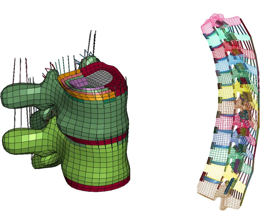
Zeng et al.                                                                                                          Thorax Model Evaluation and Validation

parametric studies were implemented to determine the properties                The process of the hierarchical improvement, evaluation, and
of the clavicles, sternum, and costal cartilages. Different failure        validation of the thorax model is presented in this section (section
thresholds using maximum principle strain (MPS) were added to              “Thoracic Intervertebral Joints Evaluation and Improvement,”
these structures to characterize the bone failure features. Several        section “Costovertebral Joints Evaluation and Enhancement,”
experimental setups were accurately replicated to simulate the             section “Clavicle Model Improvement and Validation,” section
axial compression of clavicle, bending testing of clavicle and             “Sternum Model Improvement and Validation,” section “Costal
sternum, and cantilever-beam like bending testing of costal                Cartilage Model Enhancement and Validation,” section “Ribcage
cartilages. The bone behavior of the ribs was not included here            or Full Thorax Level Validation Cases,” and section “Model
since they were already well investigated in previous studies (Li          Performance Evaluation”), and a graphical overview of the steps
et al., 2010; Poulard et al., 2015; Zaseck et al., 2018).                  of the study can be found in the Supplementary Figure 1).
    To evaluate the biofidelity of the whole thorax model, body
regional level and full thorax or torso level validation tests             Thoracic Intervertebral Joints Evaluation
were conducted across different loading conditions. These tests            and Improvement
contained point loading of the eviscerated ribcage, frontal                The T-spine was enhanced and improved by accurate
pendulum impacts, shoulder pendulum impact and table-top belt              representation of the components, material properties, and
loading tests. The biomechanical response of the thorax was                ligament failure properties at tissue level. For the intervertebral
overall deemed biofidelic and the model was found to be in                 discs (IVDs), the nucleus pulposus and annulus fibrosus ground
good agreement with the experimental data using both qualitative           substance were modeled using solid elements. For each IVD,
and quantitative assessments. The validated thorax model, as               four pairs of concentric quadrilateral layers (8 layers total)
demonstrated in this study, was able to serve as a valuable tool for       were created to represent the annulus fibrosus fiber laminae
safety researchers and automobile designers to predict, prevent,           (Newell et al., 2017), which were embedded in the ground
and mitigate thoracic injuries of vehicle occupants. Additionally,         substance (Figure 1A; Panzer and Cronin, 2009). There were
this study describes a multi-level, hierarchical evaluation and            9 major spinous ligaments of the T-spine included in the
validation strategy to enhance the biofidelity of other human              model, including anterior and posterior longitudinal ligaments,
body models for injury risk prediction and prevention.                     ligamentum flavum, interspinous ligaments, supraspinous
                                                                           ligaments, intertransverse ligaments (left and right), and facet
                                                                           capsular ligaments (left and right) (Figure 1B). The ligament
MATERIALS AND METHODS                                                      response was characterized using non-linear load-deflection
                                                                           curves identified by three distinct spinal regions (Chazal
Body FE Model Overview                                                     et al., 1985; Panzer et al., 2011). The failure deflection for
The GHBMC 50th percentile male (M50) detailed seated                       each individual ligament was adopted from data reported in
occupant (v4.5) FBM was the basis for the improvement,                     Pintar (1986).
development, and validation in this study. The model was                      Initial quasi-static evaluations of the model were conducted
developed for use with the LS-DYNA solver, a commercial non-               for adjacent vertebrae and the intervertebral disc between
linear explicit finite element analysis (FEA) program (LSTC,
Livermore, CA, United States). The anatomical geometry of
the body was reconstructed based on the anthropometric data
scanned from a 50th percentile male volunteer (Gayzik et al.,
2009). The high quality quadrilateral and hexahedral meshes of
the thorax components were generated by an interactive multi-
block meshing approach (Li et al., 2010; Poulard et al., 2015).
The FBM contained 1,036 parts, which were discretized by 2.19
million of elements and 1.26 million nodes.
    In the base thorax model, the bones of thoracic cage were
modeled as elasto-plastic materials with strain-rate dependency
(∗ MAT_Piecewise_Linear_Plasticity) in LS-DYNA, including
cortical and trabecular bones of the ribs, sternum, and clavicles.
The thoracic vertebrae were represented by rigid bodies, and
the costal cartilages were modeled as an elastic material. For
each thoracic intervertebral disc, the annulus and nucleus
pulposus was modeled as a highly compressible Hill foam (Hill,
1979) and an inviscid fluid, respectively. The thoracic spine
ligaments were defined as non-linear elastic spring beams without
failure properties. A supplemental table was provided to collect
                                                                            FIGURE 1 | FE modeling of intervertebral discs and ligaments: (A) IVD details
the material models and properties for the important parts
                                                                            (T7-T8) and intervertebral ligaments, and (B) lateral view of overall thoracic
relevant to the evaluation and improvement in current study                 spine model.
(Supplementary Table 1).

Frontiers in Bioengineering and Biotechnology | www.frontiersin.org    3                                               July 2021 | Volume 9 | Article 712656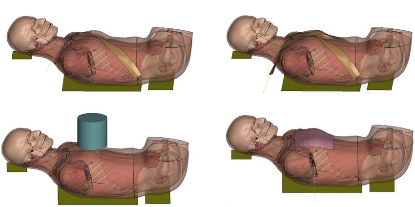
Zeng et al.                                                                                                             Thorax Model Evaluation and Validation

them (motion segment) to ensure a valid tissue-level response                        and axial compression, respectively. The FE models were created
(Markolf, 1972), including axial tension and compression,                            based on an isolated clavicle from the thorax model and modeling
shearing and lateral bending. Since the experimental testing                         for the testing device. For the three-point bending test, each
of motions segments was not able to represent natural spinal                         end of the clavicle was supported by a pinned assembly which
motions due to too many constraints imposed, the FSU with three                      allowed rotation along the superior–inferior axis. The impactor
adjacent vertebrae and two intervertebral discs was therefore                        in Figure 3A, which was modeled as cylinder with aluminum
adopted by researchers to evaluate more realistic spinal responses                   material properties, was loaded along the anteroposterior
(Yang, 2018). In our study, two sets of FSUs (T2–T4 and T7–T9)                       direction (i.e., perpendicular to the clavicle longitudinal axis)
were simulated (Figure 2A) and compared with experimental                            using the same rate as in the experiments (0.1 m/s). In the axial
testing results of flexion bending (Lopez-Valdes et al., 2011). In                   compression test, as shown in Figure 3B, the medial end was
addition to the FSU level evaluation, the full torso response and                    potted into a square-shaped block that allowed rotation, while
change of spine angle of extension were validated by tests of rear                   the lateral end was clamped and moved along the lateral–medial
hub impact loading (Forman et al., 2015) with a 97.5 kg impactor                     direction by 0.1 m/s. In the experiments, four uniaxial strain
using three different velocities: 1.5, 3.0, and 5.5 m/s, shown in                    gages were attached at the perimeter of the clavicle cross section,
Figure 2B.                                                                           as indicated by green rectangles in Figures 3A,B. Based on the
                                                                                     force-deflection responses, parametric studies of the material
Costovertebral Joints Evaluation and                                                 properties were conducted to determine the appropriate elastic
                                                                                     modulus and yield strength of the cortical bone. Bone failure
Enhancement
                                                                                     was defined using a maximum principal strain (MPS) criterion.
The costovertebral joints were evaluated at component level using
                                                                                     Through a brute-force optimization process, it was found that 8%
the method outlined in Duprey et al. (2010). To replicate the
                                                                                     MPS for cancellous bone and 3% MPS for cortical bone produced
experiment setup, the ribs 2, 4, 6, 8, and 10, along with their
                                                                                     reasonable results to the experimental data (Duprey et al., 2008).
adjacent vertebrae were isolated from the thorax base model. All
                                                                                     Once the MPS reached the defined threshold, the element was
relevant ligaments that interconnect the bony structures were
                                                                                     eroded and removed from the calculation.
preserved for each level of the costovertebral joint, including
the radiate, costotransverse ligament, superior costotransverse
ligament, lateral costotransverse ligament, and the intra-articular                  Sternum Model Improvement and
ligament. The radiate was modeled using shells and assigned                          Validation
as a non-linear fabric material. Other ligaments were modeled                        The sternum fracture was evaluated under a dynamic three-point
as tension-only beams with a single constant to define the                           bending test (Kerrigan et al., 2010). The test rig was modeled
stiffness. Each rib was inserted by a simple model of a cylindrical                  similar to the three-point bending test of the clavicle (Figure 3C).
rod, which was rigidly constrained to the rib. Four quasi-                           The impactor was put in the middle of the two posts and
static rotational motions were applied to the rod to investigate                     displaced along the downward direction (1.115 m/s) to represent
ventral-dorsal and cranial-caudal flexion, as demonstrated in                        anteroposterior loading on the sternum. Parametric studies of
Supplementary Figure 2.                                                              material properties were conducted to determine appropriate
                                                                                     sternum material parameters (elastic modulus, yield strength and
Clavicle Model Improvement and                                                       failure strain) based on experimental force-time responses.
Validation
The clavicle model was evaluated at the component level using                        Costal Cartilage Model Enhancement
experimental testing results in Zhang et al. (2014), which loaded                    and Validation
the clavicles to fracture by two methods: three-point bending                        The costal cartilage model was evaluated at the component
                                                                                     level using experimental testing data from Forman et al. (2010).
                                                                                     Figure 4 showed the testing device with potted costal cartilage
                                                                                     model, which was isolated from the segment connected to the
                                                                                     anterior border of the forth rib. The end of cartilage connected
                                                                                     to the rib (i.e., right side of the device) was constrained, and
                                                                                     the left end was loaded along the vertical direction (0.4 m/s) to
                                                                                     represent the situation of mid-chest compression. Anatomically,
                                                                                     the costal cartilage is composited of an inner solid of hyaline
                                                                                     cartilage and a surrounding tissue layer called the perichondrium.
                                                                                     During FE modeling, the solid structure of costal cartilage was
                                                                                     updated from a linear elastic material model in base model to an
                                                                                     elasto-plastic material with strain-rate dependency. Additionally,
                                                                                     a non-linear fabric shell layer that surrounded the solid mesh was
  FIGURE 2 | Model setup for flexion bending of FSU and rear hub impact test:        incorporated to include the biomechanical contribution of the
  (A) flexion bending test of FSU T7-T9, and (B) hub-impact tests performed on
                                                                                     perichondrium, since it was not explicitly modeled previously.
  the back surface of the mid-thorax.
                                                                                     The material parameters were calibrated to the reaction force

Frontiers in Bioengineering and Biotechnology | www.frontiersin.org              4                                        July 2021 | Volume 9 | Article 712656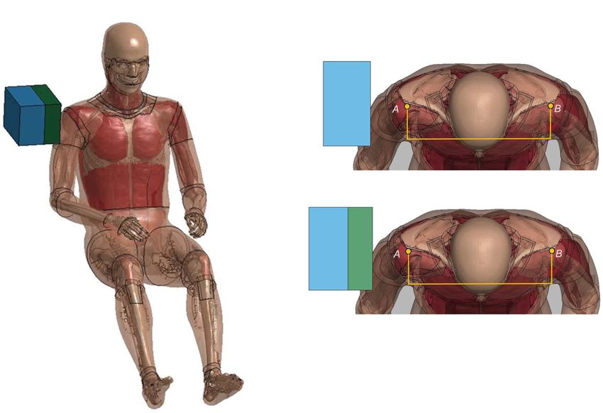
Zeng et al. Thorax Model Evaluation and Validation
FIGURE 3 | Model setup for clavicle fracture and sternum bending tests: (A) three-point bending test (the green rectangle showed the position where the strain
gages were attached), (B) axial compression test, and (C) sternum bending test.
on their relevance, the availability of data, and the large range of
structural levels they represented.
Point Loading of the Eviscerated Ribcage
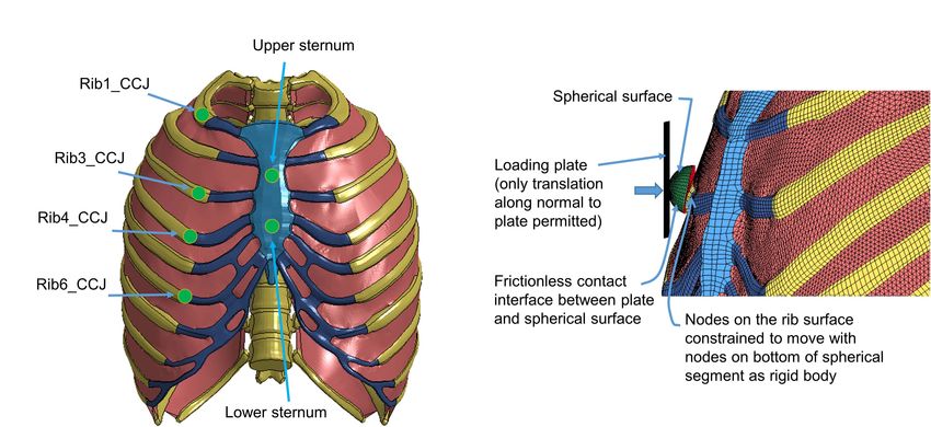
The quasi-static point loading of the ribcage was simulated
using the experimental testing approach reported in Kindig
et al. (2010). In the experiment, isolated eviscerated ribcages
were mounted upright and quasi-statically loaded by a plate
interfacing with a spherical segment glued to the superficial
surface of the ribs or the sternum. The reaction force on this
plate against applied displacement was measured to check the
biomechanical response. To simulate the testing, the FE model of
the ribcage (Figure 5) was positioned consistent with the initial
FIGURE 4 | Model setup for costal cartilage bending test. position adopted in the experiments. The loading and boundary
conditions were also set similarly to the experimental settings: the
thoracic vertebrae were constrained and a constant velocity (0.2
along the anteroposterior direction between the simulation and m/s) was imposed on the plate up to the prescribed displacement
the reported experimental data. used in the experiment (varied with the point loading site).
Frontal Pendulum Impact
Ribcage and Full Thorax Level Validation The frontal pendulum impact testing was designed to quantify the
Cases thoracic response and injury tolerance along the anteroposterior
After validating the MSK structures at the component level, the direction under midsternal blunt impact. The PMHS used in
components were integrated into the thorax model in FBM. the experiments was placed in a seated upright position, and
The overall mechanical response of the chest, which included compressed on the frontal chest by a 23.4 kg cylindrical impactor
the contribution of these MSK soft and hard tissues, could be with an initial impact velocity of 4.3 m/s and a diameter of
evaluated against a number of loading cases at ribcage or full 152 mm centered with the sternum at the level of the 4th
thorax level. Here four experimental cases were selected based intercostal space. In the simulation, the FBM was seated on a
Frontiers in Bioengineering and Biotechnology | www.frontiersin.org 5 July 2021 | Volume 9 | Article 712656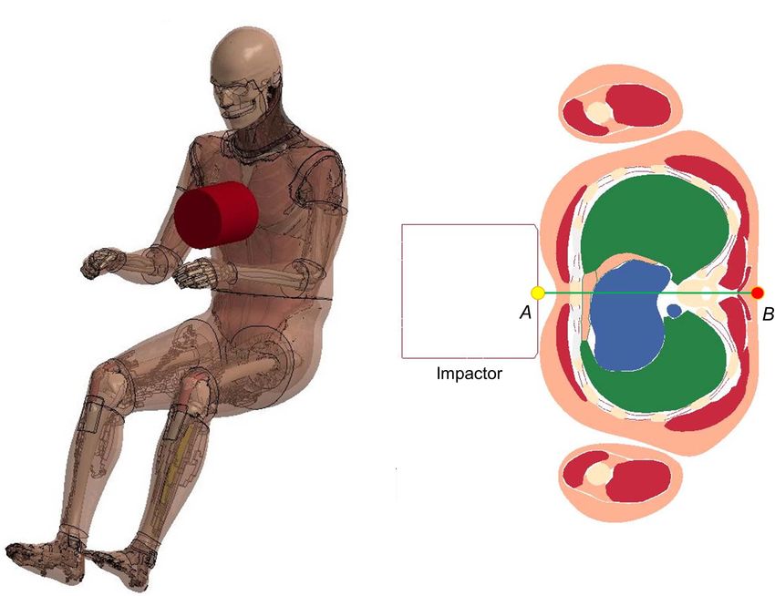
Zeng et al. Thorax Model Evaluation and Validation
FIGURE 5 | Model setup for point loading simulation: (A) illustration of the loading points at the upper and lower sternum levels and at the costochondral junction
(CCJ) of rib levels 1, 3, 4, 6, and 9, and (B) a close-up at a loading site in the FE model (Kindig et al., 2015).
rigid plate and the impactor positioned at the same mid-sternum to maintain the loading angles similar to experimental settings.
level as in the PMHS testing (Figure 6). The overall thoracic The contact force between the back side of FBM and the table
responses (deflection-time and force-deflection relationships) was output as the reaction force. The relative compression was
were reported and compared with experimental corridors (Kroell characterized in terms of the ratio of the deflection of a point at
et al., 1971; Lebarbe and Petit, 2012). the mid-sternum divided by initial distance between this point
and the table along anteroposterior direction.
Shoulder Pendulum Impact
The lateral impact on the shoulder provided response Model Performance Evaluation
characteristics and injury tolerance of the shoulder and upper To quantitatively evaluate the model performance, the outputs
thorax along the lateral direction. Koh et al. (2005) presented a between model simulations and the experimental testing were
meta-analysis of biomechanical responses from several cadaveric compared by a widely used objective rating tool known as
studies of lateral impacts on the shoulder, which were developed CORelation and Analysis or CORA (Gehre et al., 2009; Vavalle
into biomechanical response corridors for four loading speed et al., 2013; Poulard et al., 2015). The CORA can evaluate the
cases: 4.4 m/s (foam padded impactor). 4.5 m/s (unpadded), similarity between curves by the cross correlation method, which
6.4 m/s (padded), and 6.8 m/s (unpadded). To replicate the evaluates error according to phase shift, magnitude and curve
experiments, the model was seated on a rigid plate with the arms shape to produce a relative score ranging from 0 (no correlation)
down by its side (Figure 7A). The impact force was measured to 1 (perfect match) (Miller et al., 2017; Decker et al., 2020).
as the contact force between the impactor and the thorax.
The shoulder deflection was defined as the change of distance
between two nodes corresponding to the locations on humeri RESULTS
measured in the experiments (Figure 7B).
The simulation results of component level validations were
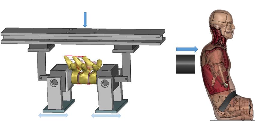
Table-Top Restraint-Like Loading Tests presented in the Supplementary Figures 3, 7, except the results
Based on the investigation of the force-deflection response of of FSU flexion bending testing and rear hub impact for T-spine.
the thorax under dynamic, non-impact, restraint-like loading The CORA ratings were collected in the Table 1.
at a non-injurious level, Kent et al. (2004) presented testing
corridors subjected to single and double diagonal belts and Thoracic Intervertebral Joints
hub and distributed loading on the anterior thorax. The limb The simulation results of adjacent vertebrae to quasi-static
amputated PMHS subjects were positioned supine on a table, external loads (force vs. disp., or moment vs. rotation) produced
and then compressed up to 20% of external chest depth for all reasonable responses (see Supplementary Figure 3) compared
four loading conditions. Four table-top FE models were set up to to experimental data (Markolf, 1972). The average CORA score
simulate the experimental loading cases (Figure 8). The pulleys was 0.85, showing good correlation with the testing data. For
were modeled using slip ring elements and 1-D belt elements dynamic flexion testing of upper-thoracic and mid-thoracic FSU,
Frontiers in Bioengineering and Biotechnology | www.frontiersin.org 6 July 2021 | Volume 9 | Article 712656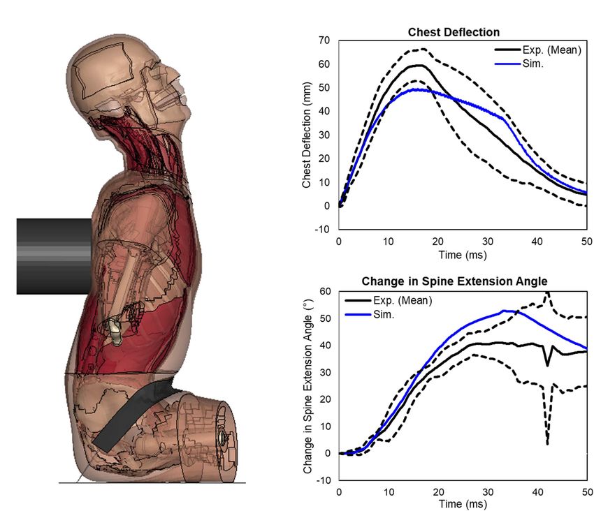
Zeng et al.                                                                                                                       Thorax Model Evaluation and Validation

  FIGURE 6 | Model setup for frontal pendulum impact simulation: (A) illustration of the impact condition. The impact force was measured as the contact force
  between the impactor and the chest, and (B) chest deflection was defined as the change of distance between the center of impactor surface and a node taken on
  the skin at the T8 level.

  FIGURE 7 | Model setup for shoulder pendulum impact simulation: (A) illustration of the impact condition (padded impact), and (B) illustration of shoulder deflection
  measured between points A and B for unpadded and padded simulation cases.

Frontiers in Bioengineering and Biotechnology | www.frontiersin.org                 7                                               July 2021 | Volume 9 | Article 712656
Zeng et al.                                                                                                                      Thorax Model Evaluation and Validation

  FIGURE 8 | Model setup for table-top loading cases: (A,B) showed the single belt and double belts loading (belts were modeled as a shell layer with 2-mm
  thickness), (C) hub loading by a cylindrical rigid hub with a diameter of 152 mm, and (D) distributed loading by an extra-wide belt (203-mm width) simulated by a
  layer of shell elements with 2-mm thickness.

ligament rupture was observed in the deformed configuration                            Nevertheless, the CORA scores of most of the simulation results
of the updated model, e.g., ligaments between T8 and T9                                was 0.7 or greater, and the response was within the range of the
(Figure 9A). The moment-angle curve generated by our updated                           experiments, except the ribs 2 under caudal motion. There were
model exhibited the toe-region followed by increasing stiffness                        also some discrepancies for dorsal motion, which often produced
that is characteristic of FSU joint response (Figures 9B,C).                           stiffer responses likely due to contacts between the ribs and the
A region with sub-traumatic damage appeared until the peak                             transverse processes. It is unknown whether a similar effect was
moment before a significant drop in response, which matched                            present in Duprey’s tests (Duprey et al., 2010).
the experimental results. The simulated peak moment before
failure was 31.8 Nm for FSU T2-T4 and 48.3 N·m for FSU T7-
T9, consistent with the experimental data. The average CORA                            Clavicle and Sternal Modeling
score was 0.81, showing an overall reasonable correlation with                         The experiment testing reported reaction forces (along the
the limited testing data. These results in the flexion simulation                      direction of loading) against the deflection, and the peak bone
showed good agreement with soft tissue injuries and failure                            surface strain against the forces. To evaluate the clavicle response,
moment described in the observed experimental testing.                                 the simulation results were compared to the response obtained
    Following the FSU validation, a validation case involving a hub                    from three-point bending tests and axial compression tests,
impact to the spine was simulated and a deformed configuration                         including the force versus the deflection and the peak cortical
was shown in Figure 10A. The impact loading to the T-spine                             bone strain versus the force. It was noted that the response
resulted in gross chest compression and forced the T-spine into                        of the base model was softer when compared to the testing
extension. For all three impact speed tests, the impact force                          data. After a parametric study of the material properties, the
response produced by the model fell within the upper and lower                         elastic modulus of cortical clavicle bone was updated from 9
bounds of the experimental data (Forman et al., 2015). For                             to 18 GPa, and the yield strength was increased from 0.08
the 5.5 m/s impact, the peak chest deflection was close to the                         to 0.16 GPa. The force-deflection response and peak strain-
lower bound of the experimental data (Figure 10B). For the                             force response obtained from updated cortical bone model were
spine extension angle, the simulation was close to the upper                           plotted, which were reasonable compared to testing data (see
bound of the experiment data (Figure 10C). Quantitatively, the                         Supplementary Figure 5).
CORA score for chest deflection was 0.94, and for the change                              For the three-point bending test of the sternum, the
in spine angle it was 0.89, showing a very good correlation with                       vertical reaction force was measured from the two supporting
the testing data.                                                                      posts, which were associated with the proximal and distal
                                                                                       ends of the sternum. The vertical force response obtained
                                                                                       from the base model showed much higher peak force than
Costovertebral Joints                                                                  the experiments. After performing parametric studies of
The results for all simulated costovertebral joints under                              material properties on cortical bone, the cortical sternum bone
each loading direction were summarized and provided in                                 modulus was reduced from 14 to 4 GPa, and reducing yield
Supplementary Figure 4. Each of the cases had 2 to 3 moment-                           strength from 0.09 to 0.035 GPa. The 2% MPS threshold
angle curves from experimentation associated with it, and                              was adopted to represent the strain based failure feature of
often there was considerable variation in the apparent stiffness.                      cortical sternum bone. The vertical reaction force response on

Frontiers in Bioengineering and Biotechnology | www.frontiersin.org                8                                               July 2021 | Volume 9 | Article 712656
Zeng et al. Thorax Model Evaluation and Validation
TABLE 1 | CORA scores for different validation cases.
Body region(s) Load cases Responses/signals CORA score
Thoracic intervertebral joints Markolf (1972) Tension 0.88
Compression 0.92
Shearing 0.90
Lateral bending 0.70
Lopez-Valdes et al. (2011) T234 (M-θ) 0.79
T789 (M-θ) 0.83
Forman et al. (2015) Chest deflection 0.94
Change in spine angle 0.89
Costovertebral joints Duprey et al. (2010) R2 ventral 0.92
R2 dorsal 0.67
R2 cranial 0.78
R2 caudal 0.17
R4 ventral 0.84
R4 dorsal 0.69
R4 cranial 0.77
R4 caudal 0.64
R6 ventral 0.84
R6 dorsal 0.69
R6 cranial 0.71
R6 caudal 0.72
R8 ventral 0.76
R8 dorsal 0.77
R8 cranial 0.78
R8 caudal 0.73
R10 ventral 0.68
R10 dorsal 0.68
R10 cranial 0.67
R10 caudal 0.72
Clavicle Zhang et al. (2014) Force-defl (three-point bending) 0.87
Force-defl (axial compression) 0.82
Strain-force (three-point bending) 0.90
Strain-force (axial compression) 0.89
Sternum Kerrigan et al. (2010) Force-time (proximal end) 0.62
Force-time (distal end) 0.53
Rotation angle-time (proximal end) 0.94
Rotation angle-time (distal end) 0.90
Costal-cartilage injury Forman et al. (2010) Force-disp (w. perichondrium) N/A
Force-disp (w/o perichondrium) N/A
Eviscerated ribcage: point loading Kindig et al. (2010) Upper sternum 0.81
Lower sternum 0.84
Rib1_CCJ 0.86
Rib3_CCJ 0.85
Rib4_CCJ 0.91
Rib6_CCJ 0.84
FBM: frontal pendulum impact Kroell et al. (1971) Deflection-time 0.98
Force-time 0.96
FBM: shoulder pendulum impact Koh et al. (2005) D-t (4.4 m/s padded) 0.78
F-t (4.4 m/s padded) 0.76
D-t (4.5 m/s unpadded) 0.87
F-t (4.5 m/s unpadded) 0.88
D-t (6.4 m/s padded) 0.99
F-t (6.4 m/s padded) 0.91
(Continued)
Frontiers in Bioengineering and Biotechnology | www.frontiersin.org 9 July 2021 | Volume 9 | Article 712656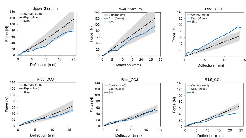
Zeng et al.                                                                                                                      Thorax Model Evaluation and Validation

TABLE 1 | Continued

Body region(s)                                Load cases                               Responses/signals                                                 CORA score

                                                                                       D-t (6.8 m/s unpadded)                                                 0.95
                                                                                       F-t (6.8 m/s unpadded)                                                 0.86
FBM: table top tests                          Kent et al. (2004)                       Force-compression (single belt)                                        0.92
                                                                                       Force-compression (double belts)                                       0.80
                                                                                       Force-compression (hub loading)                                        0.88
                                                                                       Force-compression (distributed loading)                                0.90

  FIGURE 9 | Flexion bending validation results of FSU: (A) intervertebral ligaments rupture (FSU T7-T9), and (B,C) showed the moment-angle response obtained
  from FSU T2-T4 and T7-T9.

each post was plotted and compared with the experimental                             for the fabric perichondrium shell layer) were compared to the
data (see Supplementary Figure 6). The peak force and                                results of the experimental data (see Supplementary Figure 7).
the slope of the force-time curve matched the range of the                           Compared to the FE model with perichondrium layer, the peak
testing data well.                                                                   stress obtained from the model without perichondrium decreased
                                                                                     about 45%, which was very similar to the 47% for the average ratio
                                                                                     of measured peak force from the experiment.
Costal Cartilage Modeling
The experiment reported force-displacement results of the paired
tests: perichondrium-intact and perichondrium-removed tests                          Point Loading of the Eviscerated
for each specimen. The peak forces (along anteroposterior                            Ribcage
direction) from each of the perichondrium-removed tests were                         The predicted force-deflection responses from the ribcage model
normalized by dividing them by the peak forces of the                                were compared with the experimental data (Figure 11). The
matching perichondrium-intact tests. The simulation results                          rib 1 was overly stiff to a certain extent (i.e., the force was
of the model with optimized material parameters (the elastic                         about 14% larger than the upper limit of the corridor when
modulus E = 12.5 MPa for the solid cartilage and E = 55 MPa                          the maximum deflection was reached), and the rib 6 was close

Frontiers in Bioengineering and Biotechnology | www.frontiersin.org             10                                                July 2021 | Volume 9 | Article 712656
Zeng et al. Thorax Model Evaluation and Validation
FIGURE 10 | Extension bending of spine under rear blunt impact on full torso: (A) a deformed configuration of the model under the blunt rear impact, (B) response
of the chest deflection, and (C) response of the change in spine extension angle.
to the lower bound of the corridor. The CORA scores ranged different loading conditions were reasonable compared to the
from 0.81 to 0.91. Overall, the model responses agreed with the corridors, except for the 6.8 m/s unpadded impact, where the
experimental corridors, which indicated that the ribcage stiffness peak deflection predicted by the model was smaller to some
was comparable to the tested three subjects. extent compared to the range of the corridors. Compared
to the corridor under each loading condition, the simulation
Frontal Pendulum Impact predicted peak force appeared earlier and the value was lower
than the corridor. The average CORA score of the chest
The sectional view of the thorax configuration under the
deflection for the four loading cases was 0.90, and it was 0.85
frontal pendulum impact (25 ms) was provided in Figure 12A,
for force response.
which showed the ribcage and internal organs were compressed
along the anteroposterior direction. The deflection and force
responses predicted by the model were mostly within the range Table-Top Restraint-Like Loading Tests
of the experimental corridors (Figures 12B,C). Quantitatively, In Figure 14, the simulated reaction force versus chest
the CORA score for chest deflection was 0.98, and for force compression responses agreed well with the corresponding
response was 0.90, showing a very good correlation with the experimental corridors (Kent et al., 2004). The response curve
testing results. produced by the double diagonal belts loading was slightly
outside of the corridor bounds during some chest compression
Shoulder Pendulum Impact rates (e.g., less than 7% compression). However, the response
In Figure 13, the model responses were compared with curve produced by each of the other three loading conditions
the experimental corridors, which were developed by Koh was within the corridor range. Quantitatively, the CORA ranged
et al. (2005) based on biomechanical responses from four from 0.80 to 0.90, which indicated good correlation between
cadaveric studies. The overall deflection responses under simulation and testing results.
Frontiers in Bioengineering and Biotechnology | www.frontiersin.org 11 July 2021 | Volume 9 | Article 712656Zeng et al. Thorax Model Evaluation and Validation
FIGURE 11 | Force-deflection response for the denuded ribcage under point loading on different loading sites: (A) upper sternum, (B) lower sternum, and (C–F)
displayed costochondral junction (CCJ) of the rib levels 1, 3, 4, and 6.
DISCUSSION However, it should be noted that the magnitudes of deformation
or rotation under these quasi-static loads were very small (e.g.,
In this study, a hierarchical process was presented to evaluate, the maximum displacement in the reported shear experiments
validate, and improve the musculoskeletal modeling of a mid- was less than 0.8 mm), which means slight variations between
sized male thorax for impact scenarios. At the component level, model setup and experiment were likely to cause discrepancies.
the modeling enhancement and improvement for major bony The FSU flexion bending testing applied loading until soft tissue
structures of the thorax was introduced, including the thoracic failure, which could describe the injury behavior of the upper
intervertebral joints, costovertebral joints, clavicle, sternum and and mid-thoracic spine at the segmental level. The initial toe
costal cartilages. At ribcage and full thorax levels, the thorax region of the moment response and ligament rupture were
model with validated components was quantitatively evaluated by well reproduced in the results (Figure 9) of our enhanced
four types of experimental testing. T-spine model with realistic IVD and non-linear ligaments.
It was noted that the experimental study only included two
Body Parts Validation and Improvement specimens, which produced a wide range of response curves
Most published thoracic spine models for impact analysis were and failure moments. The blunt impacts on the back of thorax
part of thoracic or whole body models with oversimplified validated the chest deflection and spine extension angle of model,
model features (Yang, 2018). For example, the GHBMC M50 which showed the overall spine kinematic response under rear
v4.5 model (version released in 2016) used drum-like closed impact agreed well with the experimental results. For non-
surfaces to represent intervertebral discs, and the spinous injurious impact testing cases (1.5 and 3.0 m/s), although the
ligaments were not included in the model. In this work, the responses of deflection and change of spine extension angle
ligaments were modeled using available material property data were not presented here, they showed good agreement with the
from available literature, and the annulus fibrosus fiber lamina experimental results. The 5.5 m/s impact velocity was designed
layers were created and embedded into the solid discs. Three for potentially injurious situation. However, it lacked spinal
levels of independent experimental tests have been conducted injury in the experiment for the first two subjects with a nominal
for validating the response of our enhanced T-spine model: stroke distance of 85 mm. The impact stroke was increased to
adjacent vertebrae/segment, FSU, and full torso. For adjacent 150 mm for the final two subjects. Our simulation was conducted
vertebrae in response to quasi-static loads (Markolf, 1972), the using 150 mm stroke distance. This explains why the simulated
results of force vs. displacement and moment vs. rotation of spine extension angle was at the upper limit of the data based
T8-T9 showed good agreement with the experimental results. on four subjects.
Frontiers in Bioengineering and Biotechnology | www.frontiersin.org 12 July 2021 | Volume 9 | Article 712656Zeng et al. Thorax Model Evaluation and Validation FIGURE 12 | Simulation results of thorax model under Kroell et al. (1971) frontal pendulum impact: (A) superior view of the cross-section of the compressed thorax at the mid-sternum, (B) deflection-time response, and (C) force-time response. FIGURE 13 | Deflection and force responses under Koh et al. (2005) shoulder pendulum impact: (A) and (B) 4.4 m/s padded impact, (C,D) 4.5 m/s unpadded impact, (E,F) 6.4 m/s padded impact, and (G,H) 6.8 m/s unpadded impact. Frontiers in Bioengineering and Biotechnology | www.frontiersin.org 13 July 2021 | Volume 9 | Article 712656
Zeng et al.                                                                                                                    Thorax Model Evaluation and Validation

  FIGURE 14 | The reaction force versus chest compression responses produced by the table top tests: (A) single diagonal belt loading, (B) double diagonal belts
  loading, (C) hub loading, and (D) distributed loading.

    The simulation of the costovertebral joints under quasi-static                    studies of material properties. The adjusted material properties
ventral-dorsal flexion and cranial-caudal flexion predicted fair                      can compensate for missing model details or geometry
to good results compared to Duprey et al. (2010) test data,                           deficiencies (Cronin, 2014), aiming to achieve better prediction
except the moment-angle produced by rib 2 caudal flexion.                             of global kinematic response and component level injury. For
This could be attributed to the limited sample and often the                          clavicle under three-point bending and axial compression (Zhang
samples themselves having wide range of response. Furthermore,                        et al., 2014), the predicted responses were within the range
the process of tuning the material properties of the ligaments                        of experimental curves and the CORA scores were good,
associated with the costovertebral joint was complicated by                           although the strain vs. force response was close to the upper
the fact that many of the beams in the model, whether                                 bound of experimental data. Qualitatively, the trends of the
they represent the costotransverse, superior costotransverse, or                      simulated results of the three-point bending of sternum agreed
lateral costotransverse ligaments, all couple and contribute to                       well with the testing data (Kerrigan et al., 2010). However,
the moment-angle relationship for the 4 simulated directions.                         the model only showed fair agreement with the experimental
Stiffening up the beams to produce a better caudal response                           results according to the quantitative CORA scores, probably due
appears to also cause substantial deviations in the cranial, ventral,                 to the large variability observed in testing data. To enhance
and dorsal relations. In a larger scope, multiple output responses                    the costal cartilage model, a layer of perichondrium with a
of a computational model could be sensitive to the changes                            fabric material was created to surround the solid mesh of the
of a specific input parameter. it is important to ensure proper                       costal cartilage. Biomechanically, the perichondrium has been
characterization of such parameters that have a significant impact                    shown to contribute approximately half of the force response
on model outputs.                                                                     under cantilever-beam like bending (Forman et al., 2010), when
    For clavicle and sternal validation and improvement, the                          comparing the normalized force-displacement curves produced
material parameters were determined based on parametric                               by perichondrium-intact model and perichondrium-removed

Frontiers in Bioengineering and Biotechnology | www.frontiersin.org              14                                              July 2021 | Volume 9 | Article 712656
Zeng et al. Thorax Model Evaluation and Validation
model. A similar distribution of reaction forces was achieved close agreement with the experimental data both qualitatively
by tuning the Young’s moduli for the costal cartilage and and quantitatively.
perichondrium. The results were within the testing range and
reported experimental error. Limitations of This Study
Detailed human thorax body models can provide insights to
investigate injury mechanisms and tolerances by qualitative
Ribcage and Full Thorax Levels assessment and quantitative evaluation of thoracic response at
Validation tissue level. However, similar to developing other human body
Once the presented body components were enhanced by models, there are some limitations of this work which may
adding more biofidelic details or adjusting material properties, or may not affect the model biofidelity. First, there were a
and validated by adopted experimental loading cases, these paucity of available experimental data or missing technical details
components were integrated into the thorax in the FBM. To regarding specific aspects of model verifications or validations.
check the stability and biomechanical responses of thorax model, Unfortunately, most experimental data were not developed or
validations were conducted under a wide variety of loading presented for the purposes of computational modeling studies
scenarios at ribcage or full thorax level. (Yang, 2018). Also, some experimental tests utilized for our model
In this study, the validated sternum, costal cartilages, and validation were conducted more than three or four decades ago.
thoracic spine were integrated into the thorax model. The Some details related to the testing subjects or test conditions
geometry and material properties of the ribs in the current thorax were missing or lacked adequate description. For instance, the
model were not changed since they were already validated in frontal pendulum impact on chest (Kroell et al., 1971) were
previous studies (Li et al., 2010; Poulard et al., 2015; Guleyupoglu published in the 1970s.
et al., 2017; Zaseck et al., 2018). The quasi-static point loading Second, there were some model simplifications due to
of the eviscerated ribcage (Kindig et al., 2010) was utilized in insufficient representation of anatomical details or material
this work to evaluate the ribcage model response with updated properties. For example, all ligaments related to the thoracic
compoments. It should be noted that experimental corridors intervertebral joints and costovertebral joints were modeled
were developed based on only three denuded and eviscerated using 1D elements, rather than a faithful representation of the 3D
PMHS. The simulated force vs. deflection curves followed the geometry. Also, the regional differences in cortical bone thickness
expected trends established in the corridors, and were lower than were not considered in this thorax model, except for the ribs.
the average experimental results, except in the case with point Third, the model presented in the current study was
loading on the costochondral junction of rib level 1 (Rib1_CCJ). not able to accurately predict local strains of the thoracic
The frontal pendulum impact (Kroell et al., 1971) was simulated skeleton. At the component level validation, the strain-force
to evaluate the global chest response along the anteroposterior response of the clavicle was compared between simulation and
direction, including the chest deflection and impact force. The experimental results, since the data was available. However,
shoulder pendulum impact (Koh et al., 2005) was modeled to reliable experimental data is needed to evaluate the strain
evaluate the overall response of the upper thorax along the lateral distribution elsewhere within the whole ribcage. Even though a
direction under four loading speed cases, including the deflection model can be validated against global impact responses, the local
and impact force. Most of these pendulum impact cases were strains of most parts at tissue level are not able to be validated
generally well correlated with the corresponding experimental since cortical strain was relatively insensitive to the model inputs
validation corridors, except some local regions. This could be (Anderson et al., 2005) in a full body loading environment. While
attributed to the modeling deficiencies of the shoulders (Xu it was noted that the rib modeling and fractures of this presented
et al., 2018), which lacked credible experimental testing data thorax model has been validated in previous studies, a newer
for validation thus far. Also, some details regarding how the probabilistic method may be a better computational strategy
corridors were produced were unknown, which could be a source in future investigations to predict rib fracture risk within FBM
of discrepancy between simulation and testing corridors. The (Forman et al., 2012).
predicted chest force vs. compression responses under the table- Finally, the current model was created based on a single mid-
top restraint-like loading tests (Kent et al., 2004) were within sized subject, which is not a real population-averaged model.
the upper and lower bounds of testing data. Quantitatively, The medical images for CAD data of this model were collected
the average CORA score was 0.88, which indicated the model from a young (26-year-old) living male volunteer (Gayzik et al.,
responses closely agreed with the corridors. 2011). Age-related factors affecting the thorax modeling such as
In summary, to develop a credible thorax FE model, there is a morphologic and material characteristics were not investigated.
need for a computational approach that can evaluate and validate The human ribcage morphology changes as it ages through
model response for the sake of achieving high biofidelity. This adulthood. Also, due to the increased porosity and decreased
work presented a hierarchical approach to validate and enhance mineralization associated with aging, the thinning of the cortical
thorax model biofidelity. Based on relevance and necessity to shell and changing bone material properties could change the
improve the current GHBMC thorax model, as well as the biomechanics and injury tolerance of the thorax (Kent et al.,
availability of experimental data, the aforementioned test cases 2005). For example, the tolerable sternal deflection level is
were selected for validation at both component and whole thorax much lower in the aging bony thorax. It is worth emphasizing
or torso levels. Overall, the model responses showed good or that the modeling and validation work presented in this study
Frontiers in Bioengineering and Biotechnology | www.frontiersin.org 15 July 2021 | Volume 9 | Article 712656Zeng et al. Thorax Model Evaluation and Validation
were focused on biofidelity and capability of injury prediction, as well as extending the framework of accurate modeling and
and further research is needed to validate the model for other multi-level validation procedure for different population groups
applications (e.g., orthopedic biomechanics). including age- and gender-based computational models.
CONCLUSION DATA AVAILABILITY STATEMENT
This work presented a comprehensive evaluation and validation The raw data supporting the conclusions of this article will be
procedure to hierarchically improve and enhance the MSK made available by the authors, without undue reservation.
system of a mid-sized male thorax FE model. The material
characteristics of relevant thoracic bony structures and ligaments
were either improved by parametric study or determined
AUTHOR CONTRIBUTIONS
based on available literature. To achieve high biofidelity, new
model features were developed and incorporated into the chest All authors contributed to the conception, design, and
components, such as thoracic intervertebral joints and costal interpretation of results presented in this study, and are
cartilage. For the sake of accurately predicting injury risk at accountable for all aspects of this work.
both component and whole thorax levels, a multi-level validation
process was presented in this study to maximize the capability
of FE model-predicted impact responses. The whole ribcage or ACKNOWLEDGMENTS
thorax model was evaluated against a wide range of loads and
different modes of loading. Compared with those corresponding This work was supported by the Global Human Body Models
experimental data sets, the CORA ratings of the model ranged Consortium (GHBMC).
from 0.76 to 0.99, indicating the model provides good predictions
of the overall biomechanical responses of the whole thorax. This
validated, highly biofidelic thorax model has been integrated into SUPPLEMENTARY MATERIAL
the newest generation of GHBMC models to represent the state-
of-the-art computational human body models for crash injury The Supplementary Material for this article can be found
prediction and prevention. Future studies will focus on tissue- online at: https://www.frontiersin.org/articles/10.3389/fbioe.
level injury predictions based on reliable experimental data, 2021.712656/full#supplementary-material
REFERENCES Deng, Y.-C., Kong, W., and Ho, H. (1999). Development of a finite element human
thorax model for impact injury studies. SAE Technical Paper, 1999–01–0715.
Aira, J., Guleyupoglu, B., Jones, D., Koya, B., Davis, M., and Gayzik, F. S. (2019). Pennsylvania: SAE. doi: 10.4271/1999-01-0715
Validated thoracic vertebrae and costovertebral joints increase biofidelity of a Duprey, S., Bruyere, K., and Veriest, J. (2008). Influence of geometrical
human body model in hub impacts. Traffic Inj. Prev. 20, S1–S6. doi: 10.1080/ personalization on the simulation of clavicle fractures. J. Biomech. 41, 200–207.
15389588.2019.1638511 doi: 10.1016/j.jbiomech.2007.06.020
Anderson, A. E., Peters, C. L., Tuttle, B. D., and Weiss, J. A. (2005). Subject-specific Duprey, S., Subit, D., Guillemot, H., and Kent, R. W. (2010). Biomechanical
finite element model of the pelvis: development, validation and sensitivity properties of the costovertebral joint. Med. Eng. Phys. 32, 222–227. doi: 10.1016/
studies. J Biomech. Eng. 127, 364–373. doi: 10.1115/1.1894148 j.medengphy.2009.12.001
Antona-Makoshi, J., Yamamoto, Y., Kato, R., Sato, F., Ejima, S., Dokko, Y., et al. El-Jawahri, R. E., Laituri, T. R., Ruan, J. S., Rouhana, S. W., and Barbat, S. D. (2010).
(2015). Age-dependent factors affecting thoracic response: a finite element Development and validation of age-dependent FE human models of a mid-sized
study focused on Japanese elderly occupants. Traffic Inj. Prev. 16, S66–S74. male thorax. Stapp Car Crash J. 54, 407–430.
doi: 10.1080/15389588.2015.1014552 Forman, J., Perry, B., Henderson, K., Gjolaj, J. P., Heltzel, S., Lessley, D.,
Beeman, S. M., Kemper, A. R., Madigan, M. L., Franck, C. T., and Loftus, S. C. et al. (2015). Blunt impacts to the back: Biomechanical response for model
(2012). Occupant kinematics in low-speed frontal sled tests: Human volunteers. development. J. Biomech. 48, 3219–3226. doi: 10.1016/j.jbiomech.2015.06.035
Hybrid III ATD, and PMHS. Accid. Anal. Prev. 47, 128–139. doi: 10.1016/j.aap. Forman, J., Poplin, G. S., Shaw, C. G., McMurry, T. L., Schmidt, K., Ash, J., et al.
2012.01.016 (2019). Automobile injury trends in the contemporary fleet: Belted occupants
Cavanaugh, J. H., and Yoganandan, N. (2015). “Thoracic injury biomechanics,” in in frontal collisions. Traffic Inj. Prev. 20, 607–612. doi: 10.1080/15389588.2019.
Accidental Injury: Biomechanics and Prevention,Third ed, eds N. Yoganandan, 1630825
A. M. Nahum, and J. W. Melvin (Berlin: Springer), 331–372. Forman, J. L., del Pozo de Dios, E., Dalmases, C. A., and Kent, R. W. (2010). The
Chazal, J., Tanguy, A., Bourges, M., Gaurel, G., Escande, G., Guillot, M., et al. contribution of the perichondrium to the structural mechanical behavior of the
(1985). Biomechanical properties of spinal ligaments and a histological study costal-cartilage. J. Biomech. Eng. 132, 094501.
of the supraspinal ligament in traction. J. Biomech. 18, 167–176. doi: 10.1016/ Forman, J. L., Kent, R. W., Mroz, K., Pipkorn, B., Bostrom, O., and Segui-
0021-9290(85)90202-7 Gomez, M. (2012). “Predicting rib fracture risk with whole-body finite element
Cronin, D. S. (2014). Finite element modeling of potential cervical spine pain models: development and preliminary evaluation of a probabilistic analytical
sources inneutral position low speed rear impact. J. Mech. Behav. Biomed. framework,” in Proceedings of The 56th Annual AAAM Scientific Conference,
Mater. 33, 55–66. doi: 10.1016/j.jmbbm.2013.01.006 (Seattle, WA), 109.
Decker, W. B., Baker, A. M., Ye, X., Brown, P. J., Stitzel, J. D., and Gayzik, F. S. Gayzik, F. S., Hamilton, C. A., Tan, J. C., McNally, C., Duma, S. M., Klinich, K. D.,
(2020). Development and multi-scale validation of a finite element football et al. (2009). A multi-modality image data collection protocol for full body finite
helmet model. Ann. Biomed. Eng. 48, 258–270. doi: 10.1007/s10439-019-02 element model development. SAE Technical Paper, 2009-01-2261. Pennsylvania:
345-7 SAE. doi: 10.4271/2009-01-2261
Frontiers in Bioengineering and Biotechnology | www.frontiersin.org 16 July 2021 | Volume 9 | Article 712656You can also read