Experimental Evaluation of Tactile Sensors for Compliant Robotic Hands
←
→
Page content transcription
If your browser does not render page correctly, please read the page content below
ORIGINAL RESEARCH
                                                                                                                                    published: 11 October 2021
                                                                                                                                doi: 10.3389/frobt.2021.704416

                                            Experimental Evaluation of Tactile
                                            Sensors for Compliant Robotic Hands
                                            Werner A. Friedl * and Máximo A. Roa

                                            German Aerospace Center—DLR, Institute of Robotics and Mechatronics, Wessling, Germany

                                            The sense of touch is a key aspect in the human capability to robustly grasp and
                                            manipulate a wide variety of objects. Despite many years of development, there is still
                                            no preferred solution for tactile sensing in robotic hands: multiple technologies are
                                            available, each one with different benefits depending on the application. This study
                                            compares the performance of different tactile sensors mounted on the variable
                                            stiffness gripper CLASH 2F, including three commercial sensors: a single taxel sensor
                                            from the companies Tacterion and Kinfinity, the Robotic Finger Sensor v2 from Sparkfun,
                                            plus a self-built resistive 3 × 3 sensor array, and two self-built magnetic 3-DoF touch
                                            sensors, one with four taxels and one with one taxel. We verify the minimal force detectable
                                            by the sensors, test if slip detection is possible with the available taxels on each sensor, and
                                            use the sensors for edge detection to obtain the orientation of the grasped object. To
                                            evaluate the benefits obtained with each technology and to assess which sensor fits better
                                            the control loop in a variable stiffness hand, we use the CLASH gripper to grasp fruits and
                                            vegetables following a published benchmark for pick and place operations. To facilitate the
                           Edited by:       repetition of tests, the CLASH hand is endowed with tactile buttons that ease
                       Perla Maiolino,      human–robot interactions, including execution of a predefined program, resetting
University of Oxford, United Kingdom
                                            errors, or commanding the full robot to move in gravity compensation mode.
                      Reviewed by:
                      Deepak Trivedi,       Keywords: tactile sensors, slippage detection, hand design, grasp stiffness, grasp benchmarking
      General Electric, United States
                      Yingfeng Shan,
     Applied Materials, United States
                                            1 INTRODUCTION
                  *Correspondence:
                        Werner Friedl       In real-world scenarios, robotic grasping is still a challenge due to the variation of object properties
                  werner.friedl@dlr.de      such as shape, weight, and friction, on top of the problems arising from the robotic components, for
                                            example, a vision system that cannot accurately identify a partially occluded object in cluttered scenes
                    Specialty section:      or a hand that cannot robustly hold the grasp when an unexpected collision happens. To robustify
         This article was submitted to      grasping applications, not only a well-engineered gripper or robotic hand is required. Additional
                        Soft Robotics,      sensorial information can also help enable more intelligent controllers, which can, for instance,
               a section of the journal
                                            detect slippage and adjust the gripping force accordingly. A review of available technologies for
          Frontiers in Robotics and AI
                                            tactile sensing, including their possible advantages and disadvantages for different applications, can
           Received: 02 May 2021
                                            be found in Kappassov et al. (2015). A more recent overview on existing tactile sensors and the
           Accepted: 14 July 2021
                                            information that can be abstracted from them is provided in Li et al. (2020). For the specific problem
        Published: 11 October 2021
                                            of slip detection in dexterous manipulation, an overview is given in Chen et al. (2018).
                             Citation:
                                               Different tactile sensors provide varying performance, depending on the situation where they are
       Friedl WA and Roa MA (2021)
    Experimental Evaluation of Tactile
                                            used. To provide a standard baseline for comparison, in this study we evaluate a number of tactile
Sensors for Compliant Robotic Hands.        sensors integrated on the same gripper, the CLASH 2F, based on the technology of the CLASH 3F
           Front. Robot. AI 8:704416.       hand (Friedl et al., 2018). For technical reasons, we restrict our analysis to the sensors that can be
     doi: 10.3389/frobt.2021.704416         integrated in this gripper. We are aware that this can leave out several modalities, such as sensors

Frontiers in Robotics and AI | www.frontiersin.org                              1                                      October 2021 | Volume 8 | Article 704416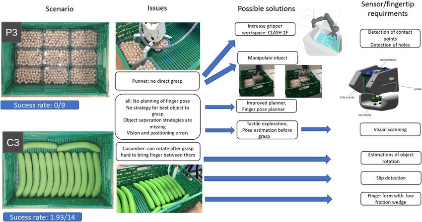
Friedl and Roa Evaluation of Tactile Sensors for Compliant Hands
specifically developed for soft hands (Wall and Brock, 2019), but detection of edges and slippage. The test procedures are applied to
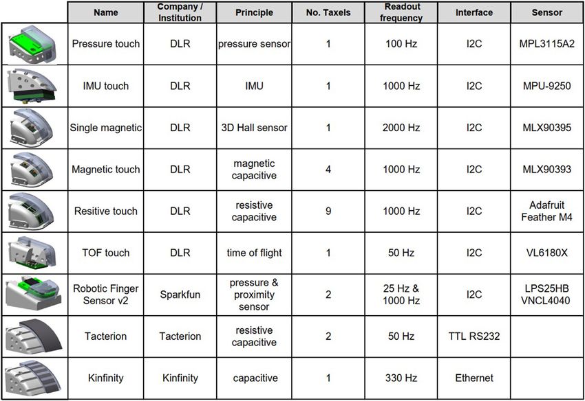
we believe our selection offers a good generic overview of tactile sensors with different underlying technology, including pressure,
sensing technologies available nowadays. To facilitate the magnetic, capacitive, proximity, or IMU-based sensors. The
interaction with the gripper and to ease teaching of poses summary of all sensors used in this study is provided in
required for the tests, we developed a user interface that can Figure 1. The main difference to consider when using these
be mounted on the CLASH 2F (also on the CLASH 3F). This user sensors is the number of taxels they provide. Single taxel sensors
interface helps to teach grasp poses of the hand and also to easily tend to be more affordable, including the commercial sensors
access basic control functions of the robot (e.g., gravity from Kinfinity, Tacterion, and Sparkfun. The Robot Finger
compensation). Furthermore, it delivers status information of Sensor v2 from Sparkfun (2021) was originally designed by
the robot and the hand by providing visual feedback to the user, Patel et al. (2018), based on an I2C proximity sensor molded
which greatly facilitates solving unexpected errors during in silicone. Now it also includes an extra pressure sensor, which
operation. helps to deal with the problem of reflections on different
For our experimental evaluation, we focused on the contact materials. If more human-like geometry at the fingertips is
information required to provide data on normal force, rough required, then sensors such as the capacitive/resistive sensor
position of the contact area, and object slippage. Normal forces from Tacterion (2021) can be used, as it can be bent in two
can be measured by different modalities, for example with simple directions. The capacitive textile sensor from Kinfinity (2021)
and unexpensive SMD pressure sensors (RightHand Robotics, uses two electrodes (compared to one electrode in the sensor from
2021; Kõiva et al., 2020) or with resistive pressure sensors as in the Tacterion), which should reduce the electromagnetic noise from
CMOS tri-axis technique with an integrated proximity sensor the environment. On the other hand, there are high dimensional
(Lee et al., 2019) or even more flexible as in Büscher et al. (2015). sensors, which have changeable silicone pads, such as the resistive
Also, a capacitive sensor can be used to detect contacts, for sensor array or the tri-axis magnetic MLX90393 sensor. In
instance using 3D printed sensors as in Ntagios et al. (2019). general, for a real application the fingertips should be easily
For detecting slippage, we can observe the shear and normal force exchangeable as the silicone pads must be changed with
and then adjust the normal force at a contact point (Ajoudani certain frequency to deal with wear and contamination.
et al., 2016; Contactile.com, 2021; Tomo et al., 2018) or detect the
slippage by processing and interpreting the sensor signals 2.2 Construction of the Sensors
(Nakagawa-Silva et al., 2019; Rosset et al., 2019). Multi-modal Besides the commercially available sensors, which are adapted to
sensors as in Ruppel et al. (2018) and Weiner et al. (2019) can work on the CLASH 2F gripper, we decided to try out different
provide additional information for object identification, sensor modalities using the same base hardware. We self-
including, for instance, shear force or temperature of the object. developed tactile sensors based on ToF (Time of Flight), IMU,
To verify the applicability of the sensors to a real use case, we and pressure, embedding the sensor and the required structure
used a benchmark proposed in Mnyusiwalla et al. (2020) for for providing a single taxel in a suitable exchangeable fingertip to
logistic use cases. We used two benchmark scenarios involving be mounted on the gripper. We have empirically found out that
cucumbers and punnets, where all grippers shown in silicone pads are more robust and give better friction properties
Mnyusiwalla et al. (2020) failed, and we tested here if than PU (Polyurethane) pads, as used for example in the DLR
additional sensor information helps to solve the intended Hand II (Butterfass et al., 2001; Grebenstein et al., 2019), so we
tasks. After trying the two selected scenarios using the CLASH decided to use silicone for the finger pads. The transition from the
2F, we verified that now our system performs much better. For the soft pad material to the hard finger structure is always
scenario where one full layer of cucumbers fills the crate, we were problematic, as the soft pad tends to detach easily from the
able to retrieve all of the aligned cucumbers by implementing an supporting structure. A bonding agent such as Wacker
adapted vision and planning strategy. The additional information Haftvermittler HF86 can be used, and it leads to good results,
from the implemented sensors also allows us to successfully grasp as obtained, for instance, with the AWIWI II hand (Friedl et al.,
all objects in the second tested scenario, a crate filled with one full 2015), but the bonding agents pose a risk for human health, so we
layer of punnets. The addition of tactile sensors allows us to decided to try a different approach. For the single axis sensors, for
prevent multiple failed grasps, as we use them to trigger error- example the tactile sensor based on pressure, the contact surface
coping strategies such as repositioning the gripper. We can now with the finger structures can be enhanced (in order to increase
also detect slippage and objects that rotate inside the hand, and adhesion with the soft pad) using holes in the supporting part, as
adapt the grasp or the arm motion accordingly. shown in Figure 2.
For changeable finger pads, it is not easy to increase the
contact surface with the underlying structure. To solve this
2 HARDWARE: CLASH 2F GRIPPER AND problem, we decided to use an underlying mesh wire that is
TACTILE SENSORS glued to the frame and provides support to the molded polymer
(Figure 2). Furthermore, the mesh wire can be soldered together
2.1 Tactile Sensors and can also be connected to a wire in order to use it as a
This study compares the performance of different tactile sensors capacitive sensor. We connected this sensor to the Tacterion
by testing several aspects, including sensibility depending on the electronics to read out the values by the sensor bridge provided in
finger stiffness and the object material, and their applicability for this board. We tried to use the Tacterion electronics also for the
Frontiers in Robotics and AI | www.frontiersin.org 2 October 2021 | Volume 8 | Article 704416
Friedl and Roa Evaluation of Tactile Sensors for Compliant Hands
FIGURE 1 | Tactile sensors used in the comparative study, including self-made and commercially available sensors.
FIGURE 2 | Self-made tactile sensors: (A) casting mold for the pressure sensor (before casting); (B) casted pressure sensor and “bone” (fingertip structure) with
holes for simple sensors such as pressure sensors, IMU, or VL6180X; (C) casting mold and resulting silicone pad for the magnetic four-axis sensor; and (D) fingertip
structure with four integrated MLX90393 sensor chips and silicone pad ready for assembly.
Kinfinity sensor, but the capacity was too low to get useful values, order to grasp large objects. The distal phalanx of the fingers was
so we used the Ethernet-based electronics from Kinfinity, with a redesigned to allow a quick exchange of the fingertips.
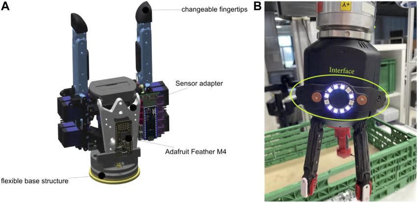
readout frequency of 300 Hz. Furthermore, the new distal phalanx allows the integration of
a sensor bridge with the Adafruit Feather M4, which collects all
2.3 Gripper for Experiments the data from the different sensors and transmits them to the
To provide a unified hardware baseline for the testing and to hand controller. The hand control PCB, based on an Arduino
simplify the effort for mechatronic integration of multiple Micro, has limited memory and CPU power, and it is not able to
sensors, we decided to use the CLASH 2F gripper, based on integrate all sensor libraries or machine learning algorithms
the same technology as the CLASH 3F hand. The fingers in required, for instance, for slippage detection.
CLASH 2F reuse the thumb modules of CLASH 3F, and it also has The gripper also includes a flexible base located right after the
two extra DoF (Degrees of Freedom) at the base, to tilt the standard connector to the robotic arm, whose movement is
modules and increase the opening distance to over 260 mm in measured with two Melexis MLX90935, each one of them
Frontiers in Robotics and AI | www.frontiersin.org 3 October 2021 | Volume 8 | Article 704416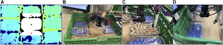
Friedl and Roa                                                                                                  Evaluation of Tactile Sensors for Compliant Hands

  FIGURE 3 | CLASH 2F gripper. (A) Two-fingered gripper with two thumb modules and a flexible base structure. (B) User interface for commanding the hand.

containing 3-DoF Hall sensors (Figure 3). We included this                         is not reachable with the kinematics of the hand. Hence, the user has
flexible hand base inspired by previous benchmark results                           to teach the robot a motion that separates the desired object from
obtained in Negrello et al. (2020), where hands with such                          the other ones, so that enough space is available around the object to
base, namely the hands presented in Deimel and Brock (2015);                       be able to grasp it. We compared the programming of this sequence
Catalano et al. (2014), had much better grasp stability in front of                with the input device against a GUI-based programming with a
unexpected collisions with the environment, compared to the                        mouse and a screen at the robot setup. For the task of kinesthetic
CLASH 3F hand. With the sensors used to measure the position                       teaching to grasp one punnet with the user interface, we get three
of the flexible base and the information on the finger position, a                   trials with an average time of roughly 35 s. However, the same task
single contact point on the finger can be calculated [the process is                using the GUI for switching between modes of the robot and the
comparable to finding the contact point where a perturbation                        hand takes around 60 s. These pilot tests showed that an optical
force is applied to a robot arm by using a 6-DoF force–torque                      feedback to indicate the user if the actual frame is saved (by
sensor at the base of the robot arm (Shujun Lu et al., 2005;                       activating during 0.1 s the pink LEDs in the ring) greatly
Iskandar et al., 2021)].                                                           improves the handling and programming of the system.
                                                                                   Figure 4 shows the different modes of operation of this user
2.4 Gripper User Interface                                                         interface.
A repeated use of the gripper in benchmark scenarios, such as the
exemplary ones used in this study, requires a simple interface to
command the hand and the robot, which should facilitate                            3 SENSOR TESTS
human–robot interactions, including execution of a predefined
program, resetting errors, or commanding the full robot to move                    This section presents the testing procedures performed to identify
in gravity compensation mode. Some commercial robots or                            how the finger stiffness and the object material might affect the
grippers include a similar interface, for example, the robotic                     sensor sensibility, and then how the sensors can be used to detect
arm from Franka Emika (2021), or the gripper from Schunk                           slippage and edges, which are two critical features to enable more
(2021). Our setup uses the KUKA LWR robot, which has no user                       robust robotic grasping procedures.
interface, so we created a mountable one to control both arm and
hand and to provide feedback to the user using LED lights, as
shown in Figure 3.                                                                 3.1 Analysis of Sensor Sensibility Depending
    The interface has four capacitive buttons, two RGB LEDs on                     on the Finger Stiffness
the right and the left side, and a LED ring with twelve LEDs from                  To get an initial insight into the behavior of the sensor
Adafruit plus an Adafruit ItsyBitsy to control the LEDs and to                     sensibility depending on the joint stiffness, we used the
read the button inputs. The micro-controller is connected over                     thumb module of the CLASH 3F hand and a fixed 3 × 3
the I2C sensor port of CLASH, which also delivers 5V and motor                     resistive sensor array to measure forces applied by the thumb
power. The sensor port can be used to mount different sensors,                     (Figure 5). We tested four different pretension values k, which
cameras, and a wrist or a user interface on the hand.                              directly correlate with the finger stiffness: 100% pretension is
    To verify the interface and its behavior in practice, we used a                equal to 100% of the maximum actuator force. With the known
simple test scenario. The user has to program how to grasp a punnet                coupling matrix for the finger (Friedl et al., 2018), its null space,
in the benchmark scenario P2 in Mnyusiwalla et al. (2020). A direct                and the force-to-stiffness relation for the FAS (Flexible
grasp with CLASH 3F is not possible, as a two-finger diagonal grasp                 Antagonistic Springs, Friedl and Roa, 2020), the

Frontiers in Robotics and AI | www.frontiersin.org                             4                                       October 2021 | Volume 8 | Article 704416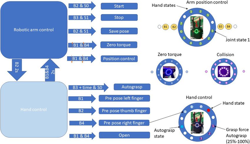
Friedl and Roa                                                                                                             Evaluation of Tactile Sensors for Compliant Hands

  FIGURE 4 | Modes of operation of the user interface in the CLASH hand. The left side shows the two operation modes and the possible button combinations to
  control the arm or hand. On the right side, the possible LED status information is shown. For example, for teaching one waypoint the user should press button B2 to
  switch on the robot, and the control state changes from S0 to S1. Now the user can press B1 and B4 for the zero-torque (gravity compensation) mode and can move the
  robot to a desired position. The zero-torque mode is confirmed by a blue LED ring. To save a new position, the user presses B2 and gets a short feedback with pink
  LEDs, to confirm that the position is saved. To grasp an object, the user has to press B2 for at least 2 s to switch to the hand control (grasp) mode. With the buttons B1,
  B3, and B4, the user can change the pre-grasp pose of each finger. To grasp the object the user has to press B3. The press duration changes the grasp force, as
  indicated by the LED ring.

  FIGURE 5 | Sensor sensibility depending on finger stiffness. (A) Contact force depending on stiffness and finger velocity for the CLASH 3F thumb. (B) Testbed with
  the thumb, and a fixed resistive sensor array.

corresponding joint stiffness can be obtained. For the test, we                            and the applied force builds up at a slower rate, thus the force is
moved the thumb toward the sensor at different velocities,                                 lower when the contact is detected. For our intended use cases,
stopping the test when we detected the contact with the                                    we require high sensibility to low contact forces, so we focus our
touch sensor. Figure 5 shows the results of this initial test.                             subsequent test only on low pretension values.
Note that the contact force increases with higher stiffness. With                             The testbed for the next test follows the same principle, but
lower stiffness, the finger can compliantly adapt to the contact                            now using the CLASH 2F, as shown in Figure 6. The contact

Frontiers in Robotics and AI | www.frontiersin.org                                     5                                           October 2021 | Volume 8 | Article 704416
Friedl and Roa                                                                                                          Evaluation of Tactile Sensors for Compliant Hands

  FIGURE 6 | Testbeds for verification of the tactile sensors on the CLASH 2F. From left to right, testbeds for: sensibility depending on stiffness, sensibility
  depending on surface materials, edge detection, and slippage detection.

  FIGURE 7 | Detected contact force for all nine sensors depending on joint stiffness and joint velocity. The blue line shows 0% pretension (corresponding to a
  stiffness of 0.23 Nm/rad and 0.12 Nm/rad in the base and distal joint, respectively) and the orange line 12.5% pretension (corresponding to a stiffness of 0.34 Nm/rad
  and 0.16 Nm/rad in the base and distal joint, respectively).

force was measured by a KD24s sensor from ME-                                            1) Place the finger at the start position, 2 cm away from the sensor.
Messsysteme, which includes a 2 N force gauge. We used                                   2) Move the finger with an angular velocity of 5°/s toward
two pretensions and different joint velocities and repeated the                             the force sensor and stop when the force sensor reaches
test 10 times for each combination. We then calculated the                                  a detected force of 10 mN, save the finger position as cp.
medium and standard deviation of the detected contact force.                             3) Now repeat the open-close cycle with a threshold of
The pretension of zero is equal to a joint stiffness of 0.23 Nm/                            50 mN and record the sensor signal of the tested tactile
rad in the base joint and 0.12 Nm/rad in the distal joint. If we                            sensor.
increase the pretension to 12.5% we get stiffness of 0.34 Nm/                            4) Analyze the recording to get the minimum threshold for each
rad and 0.16 Nm/rad in the base and distal joint, respectively.                             sensor. The threshold should be higher than two times
The maximum joint stiffness is 1.04 Nm/rad without any load                                 the noise
on the finger.                                                                            5) Now increase the velocity to 25°/s and drive the finger toward
   The procedure to perform this test is as follows:                                        contact until it reaches the tactile sensor threshold.

Frontiers in Robotics and AI | www.frontiersin.org                                   6                                          October 2021 | Volume 8 | Article 704416
Friedl and Roa                                                                                        Evaluation of Tactile Sensors for Compliant Hands

6) Check if the finger position is equal or larger than cp; if true          is missed, we artificially punish this with a high contact force
   then save the sensor threshold, and if not then save as result           value. The procedure for this test includes the following steps:
   5 N (a high value artificially selected) to punish sensor failures.
7) Repeat the previous step 10 times and then increase the                  1) Place the finger at the start position, 2 cm away from the insert.
   angular velocity with increments of 25°/s, repeat this                   2) Move the finger with an angular velocity of 5°/s toward the
   sequence until reaching 175°/s.                                             plate and stop when the FAS sensor reaches a force of 30 mN,
8) Increase the stiffness of the finger, if possible, and repeat the            save the finger position as cp.
   previous steps.                                                          3) Now increase the velocity to 50°/s.
                                                                            4) Drive the finger in contact until it reaches the tactile sensor
   The visual summary of results is provided in Figure 7. Note                 threshold (determined in the previous test).
that for increasing angular velocities, the applied contact force           5) Check if the finger position has reached or surpassed cp; if true
increases, but on some sensors a higher stiffness can reduce the               then save the sensor threshold, and if not then save 5 N as
detected contact force for high joint velocities such as for                   result to punish sensor failures.
VL6180X, or with a stronger effect on MLX90395. Note that                   6) Repeat the previous two steps 10 times.
for higher stiffness the finger stops faster, because the finger is           7) Rotate the wheel for using the next material plate, and repeat
not overshooting so much (going beyond the stop position cp)                   the procedure until all materials are tested.
and it is also storing less energy in the springs. Sensors with high
readout frequency such as the resistive sensor MLX90395, or the                 For the VL6180X, this procedure unfortunately does not work
proximity sensor VL6180X can cope better with this problem, as              properly, as the contact force can be very low, and it will not be
they will quickly detect the increase in contact force and trigger          detectable with the FAS. Figure 8 shows the results for the two
earlier the stop of the finger. Note also that the IMU does not              optical sensors and the magnetic one; the rest of the sensors do
work so well for low velocities, which can be seen on the high              not react differently for different materials. All tests were
values obtained at these low velocities. Due to the low impulse at          performed with a joint velocity of 50°/s and a stiffness given
the contact, the value is below the threshold of the sensor and             by 12.5% pretension. VL6180X has problems with highly
the FAS has to stop the finger. The lowest contact force of                  reflective materials such as steel, or with translucid materials
around 2 g can be achieved by VL6180X, followed by                          as the transparent acrylic glass, which results in a sensor error not
VNCL4040, and then comes the capacitive mesh with around                    handled by the control, and the wrong sensor value indicates the
3 g of detected contact force. The Kinfinity sensor also behaves             controller that there is a contact when there is actually none. For
quite well, but for low stiffness and low velocity the sensor               future use of the sensor, the error bit has to be readout and the
generates too many false-positives, which come from unfiltered               control has to switch to a different sensor modality to sense the
peaks in the measurement. If we use the torque sensor values                contact. VNCL4040 also has problems with the transparent
based on the measurement of the FAS to stop the finger, we can               material and with the black PLA, which generates a signal too
reach around 30 g, which agrees with the result from Friedl and             low to stop the finger. The control stateflow stops the finger if the
Roa (2020).                                                                 FAS torque reaches more than 0.4 Nm, as observed in the results
                                                                            of Figure 8.

3.2 Analysis of Sensor Sensibility Depending                                3.3 Analysis of Slippage Detection
on the Surface Material                                                     For handling a large variety of products differing in weight, size,
Another interesting aspect to evaluate is the behavior of the               and stiffness, adapting the grasping force to provide just the
sensors when grasping objects made out of different materials,              required force to grasp the object while avoiding slippage is
which happens very often in real applications. Naturally, it                paramount. To verify the slippage detection with the different
is expected that the optical sensor will have problems                      sensors, we created a testbed with a plastic wheel made of white
with transparent or highly reflective materials. Also, the                   PLA, shown in Figure 6, which contains surfaces with different
magnetic sensor can react properly mainly for magnetic                      roughness to test if a given sensor can detect slippage or not. The
materials such as steel. To test this aspect, we created a                  slippage detection requires, in general, a readout frequency
testbed that uses a wheel where small plates of different                   higher than 50 Hz, as demonstrated in Holweg et al. (1996).
materials can be inserted for testing (Figure 6). In our tests,             Hence, we did not test the Tacterion sensor nor all pressure
we used six materials: magnetic steel, non-magnetic steel,                  sensors, as they cannot be read out at that high frequency. The
white PLA (polylactide), black PLA, wood, and a                             magnetic three-axis sensor can detect slippage before it
transparent     acrylic   glass    (PMMA       -     polymethyl             happens, by observing the proportion between normal force
methacrylate). As a reference sensor to generate the                        and shear force. For the other sensors we can analyze the signal
ground-truth contact force, we used the FAS of the hand,                    by Fast Fourier Transform (FFT) or with Discrete Wavelet
which makes the testbed simpler, but the results are less                   Transform (DWT) to detect slippage. All sensors were tested
accurate than those obtained with the force sensor used in                  30 times with different slip velocities and positions on the wheel.
the previous case. The finger is commanded to close and touch                The internal torque sensing of the finger was used to set the
the plate. The forward kinematics of the finger indicates if the             contact force against the wheel. The steps followed in the test are
finger should be already in contact with the plate; if the contact           given below:

Frontiers in Robotics and AI | www.frontiersin.org                      7                                    October 2021 | Volume 8 | Article 704416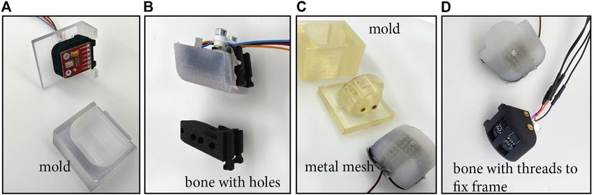
Friedl and Roa                                                                                                            Evaluation of Tactile Sensors for Compliant Hands

  FIGURE 8 | Contact force depending on the material, for the magnetic, proximity and ToF sensors (left to right).

  FIGURE 9 | Slippage detection using different sensors. For each sensor we show the raw sensor signal, Discrete Wavelet Transform (DWT) and the motion of the
  wheel in one plot, and a spectrogram plot of the sensor signal in the plot below. Note that for MLX90395 instead of the DWT we show a slip signal, based on Eq. 1. A high
  response in the spectrogram indicates that the signal can be well detected using the DWT, for example, for the IMU, which shows a clear response when the wheel starts
  to rotate. On the other hand, the Kinfinity signal is too noisy to differentiate slip from noise.

1) Place the finger at the start position, 2 cm away from the wheel.                       For a more demanding application, we would have to consider a
2) Activate the friction wheel to rotate randomly between 0 and 360°.                     sensor enclosed in an opaque medium at the outer hull of the pad
3) Drive the finger in contact, with a contact force of 2 N.                               in order to obtain a better force signal, independently of the object
4) Start to log the tactile sensor values.                                                material. The Kinfintiy and the pressure sensor fail in this
5) The friction wheel starts to rotate with a random velocity from                        detection due to the high noise in the signal (filtering the
   5 to 75°/s.                                                                            signal did not help). The resistive sensor works in some
6) Save the logged data.                                                                  occasions, but not in all 30 trials. This can be explained by the
7) Repeat all the previous steps until completing 30 trials.                              construction of the sensor: the sensing electrodes lie on a flat PCB,
                                                                                          and the resistive material is a plastic sheet of velostat, which is
   Figure 9 shows an example of the results. As expected, the                             glued to the PCB. The silicone pad above the PCB has a 3 × 3
IMU and MLX90395 work well for different velocities; also                                 structure, which mimics the form of the electrodes to reduce
VNCL4040 can detect slip quite well using DWT. The IMU                                    crosstalk. The perceived signal strongly depends on a uniform
sensor works on all surfaces of the wheel, while for MLX90395 the                         force transmission by the silicone, which is not guaranteed by this
contact point should be near the sensor to get a suitable signal.                         construction. A better sensor for this purpose would be filled up
This also applies to the VNCL4040 sensor, where the detection is                          with a thin silicone film first, to mount afterward the
influenced by the optical properties of the silicone and the object.                       exchangeable pad above.

Frontiers in Robotics and AI | www.frontiersin.org                                    8                                            October 2021 | Volume 8 | Article 704416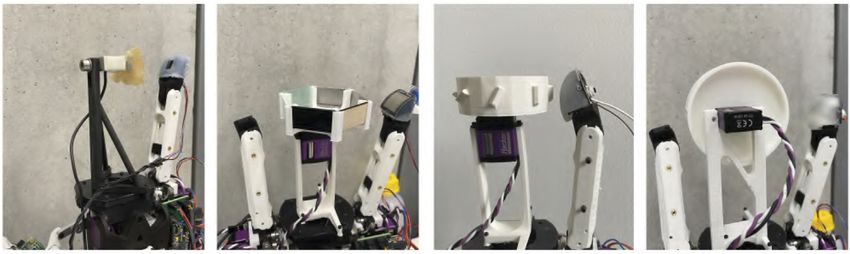
Friedl and Roa                                                                                                    Evaluation of Tactile Sensors for Compliant Hands

  FIGURE 10 | Radar plot to show the edge effect on the different sensor taxels for the resistive and MLX90393 sensors.

   Using the information of the detected slip, we can integrate                      the sensor would help. For our final benchmark in the next
this detection in the automatic grasp state machine of CLASH                         section, we decided to use a fingertip with a flatter pad.
using the following steps:

1) Bring all fingertips in contact with the object, verifying the
                                                                                     3.4 Analysis of Edge Detection
                                                                                     Another aspect highly relevant for a tactile sensor is its ability to
   contact with the finger torque sensors and fingertip tactile
                                                                                     differentiate geometric features. For a grasping application in logistics,
   sensors.
                                                                                     for instance, the detection of edges can help to secure difficult objects.
2) Lift the object, while analyzing normal and shear force.
                                                                                     Another case happens if an object is rotating within the hand after the
3) If shear forces get higher than the limit permitted by the
                                                                                     grasp is performed; the grasp is not anymore the nominal one used for
   normal force, increase (stepwise) the normal force until no
                                                                                     collision-free path planning, and the object might hit obstacles during
   more slippage is detected (or until the force cannot be
                                                                                     transportation. The early detection of the rotation helps to adjust the
   further increased). The required torque at the motors is
                                                                                     path or to readjust the grasp using external forces (Chavan-Dafle et al.,
   computed using the Jacobian matrix for the contact
                                                                                     2014). Note, for instance, that for a cylindrical object, the sensor
   position.
                                                                                     perceives a similar signal when grasping the cylinder along its length or
4) When an “open” command is given, stop slippage observation
                                                                                     when touching an edge. We implemented a testbed, shown in
   and open the hand.
                                                                                     Figure 6, where a wheel with edges on its periphery is mounted
                                                                                     on the central part of the hand. The wheel has 8 edges, oriented in 22.5°
   The detection of slippage uses, as an underlying
                                                                                     steps and with a height of 5 mm above the wheel. The test procedure
assumption, a simple friction cone model (Wettels et al.,
                                                                                     for the edge detection has the following steps:
2009); slippage occurs if the tangential force (vectorial sum
of t x and t y ) exceeds the normal force (t z ) times the friction
                                                                                     1)   Place the finger at the start position, 2 cm away from the sensor.
coefficient (μf ). The factors c x , c y and c z are calibration
                                                                                     2)   Choose a random edge on the edge wheel.
factors in this expression for the non-slippage condition:
                                                                                     3)   Drive the finger toward contact with a contact force of 3 N.
                                     cz tz
                          1 < μF                        (1)                 4)   Log the tactile sensor values.
                                  cx tx2 + cy ty2                                    5)   Repeat 20 trials per edge.

which assumes that the normal force (z-component) of the                                 We tested both multi-taxel sensors, the 3 × 3 resistive, and the
sensor is the dominant one. However, if the contact is far                           sensor with the four MLX90393, which would be capable of
away from the center of the sensor, as it could happen for                           differentiating the edges thanks to their higher spatial resolution
instance with MLX90395 embedded in a round fingertip,                                 (resistive sensor: 2 mm, MLX: 10 mm). The results obtained with
another component of the force can actually dominate the                             the procedure described above can be nicely visualized in a radar plot,
sensor output and the slippage model will lead to inaccurate                         as shown in Figure 10. Unique shapes of the areas guarantee that the
results. A workaround would be adjusting the coordinate                              edges can be discerned quite well; also, the plots help to recognize the
frame so that the z-axis is aligned with the highest force                           sensor that best identifies the edges in different orientations. Note that
direction after the initial grasp, or building a flatter finger                        with the measurements of the four MLX90393, it is hard to discern the
pad to guarantee that the z component is always dominant in                          different edge orientations, as the resulting areas are quite similar for
the sensor output using the initial coordinate frame. Also, re-                      most of the tested orientations. The test was run with a threshold value
orientating the finger to achieve a contact point directly over                       of 0.3 Nm for the base torque sensors of the fingers, and repeated with

Frontiers in Robotics and AI | www.frontiersin.org                               9                                        October 2021 | Volume 8 | Article 704416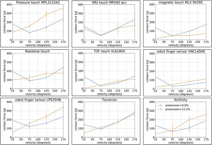
Friedl and Roa Evaluation of Tactile Sensors for Compliant Hands
FIGURE 11 | Summary of performance characteristics for all the tested sensors.
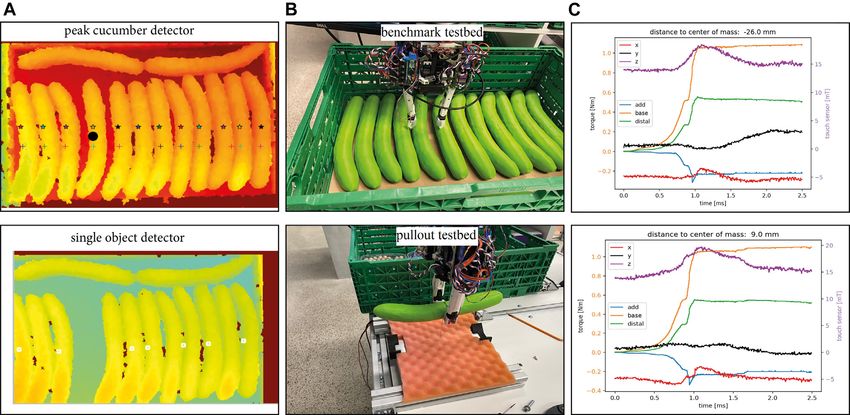
FIGURE 12 | Derivation of requirements from the benchmark tests by analyzing the original failures for the study from Mnyusiwalla et al. (2020) for a crate completely
filled with punnets (scenario P3) or cucumbers (scenario C3).
all edges on the wheel. The resistive sensor array shows clear signals this application. The mesh capacitive sensor, for instance, is
over multiple trials for the different edges. Machine learning simple to build and relatively easy to read out, and the mesh
approaches could help for generalizing the detection for random stabilizes the silicone pad. VL6180X provides a more precise
orientations of the edge. distance measurement, which can be helpful to use it as a
scanning sensor for pre-grasp adaptation. Due to the results
3.5 Multi-Modal Sensors of the edge detection test, it is clear that a suitable spatial
From the previous tests, we can observe that different sensors resolution is required to properly detect object rotations; the
have different strengths, and some of the sensors cannot even tested commercial sensors would have to be adapted for this
be applied to some of the tests. An overview of all sensors and application by asking the vendors for a sensor with better
their main performance characteristics is shown in Figure 11. resolution. We decided to focus on the resistive sensor for
This table can be used to guide the construction of a multi- detecting the contact position and orientation, in
modal sensor for different scenarios For instance, optical combination with one or more MLX90395 as shear force
sensors have problems with different materials and should be sensor. Complemented with the IMU as fingertip orientation
not used alone, but they deliver interesting information for and slip detector, we could then create a multi-modal
pre-contact detection. Also, the capacitive sensors can be fingertip that provides all the required information to
used as proximity sensor, as they are also quite sensitive for robustify a grasp execution. VNCL4040 could be still an
Frontiers in Robotics and AI | www.frontiersin.org 10 October 2021 | Volume 8 | Article 704416Friedl and Roa Evaluation of Tactile Sensors for Compliant Hands
FIGURE 13 | Scenario C3. (A) Vision algorithms. (B) benchmark testbed and pullout testbed. (C) Output of the MLX90395 sensor during pullout tests, where the
y-component (black line) clearly signals if a cucumber rotates inside the hand. The orange, green, and blue lines (with corresponding scale in the left y-axis) show the
finger joint torques; the object rotation cannot be detected by them, as they do not change after the rotation starts. The red, black and magenta lines (with corresponding
scale in the right y-axis) show the response of the tactile sensor in the three directions x, y and z.
option for slip detection and proximity; however, it requires sequence, if any motion fails, a state estimation based on the
larger space for integration, especially if we want to generate a sensors would improve the success rate, as it would promptly call
multi-modal fingertip adaptable to the CLASH gripper. for a corrective action or a replanned strategy. For the new
CLASH 2F, we set up a PyBullet1 simulation (Figure 12) to
verify if it is possible to grasp the punnet on the long side, or even
4 BENCHMARK TEST diagonally, to be able to grasp it directly without any complex
sequence. In fact, both options are possible due to the hand
To test the applicability of the selected sensors, we use a published kinematics, which allows the hand to adapt and grasp light objects
benchmarking framework for pick-and-place tasks, designed up to a size of 250 mm (the punnet dimensions are 115 mm x
originally for the logistic domain (Mnyusiwalla et al., 2020). It 175 mm). However, the diagonal grasp is hard to stabilize, but
entails picking up fruits and vegetables from a container and this would be in principle possible using, for instance, the
placing them in an order bin. The original benchmark proposed MLX90395 sensors, as we would be able to measure in which
scenarios with different degree of difficulty. In particular, two of the direction the punnet slips and then adapt the position of the
scenarios, named C3 and P3, were not solved by any gripper or hand fingers. This approach needs a signal on the MLX90395 sensors,
in the original study. Those scenarios, depicted in Figure 12, deal with which are in the middle of the finger pad, to detect the rotation
grasping objects from a crate, where the crate is completely filled with angle of the punnet. A feasible strategy is then a combination of
cucumbers (scenario C3) or punnets (scenario P3). direct access on the long side of the punnet and then a simple
First, we revisited the initial results of the benchmark, move to come between the punnets and grasp one of them. For
analyzing the root causes for failure, in particular for the the scenario C3 with the cucumbers, also the first grasp is critical,
CLASH hand, as shown in Figure 12. Some of the identified and it is the hardest one to get, as there is little space for inserting
problems, mainly the lack of a local planner for finger poses in a finger for the first grasp. This could be improved with a more
such a cluttered environment, were recently solved in Sundaram wedged finger. We developed a first prototype of such new
et al. (2020). The main challenge in the punnet scenario P3 is that fingertip, as shown in Figure 12. The fingertip includes
a direct grasp of the objects is not possible. The difficulty is greatly multiple sensor modalities, and follows the ideas presented in
reduced after the first punnet is retrieved, but this requires some Section 3.5. VL6180X helps find the hole between the punnets
smart sequence of steps, for example, find a hole between the and the correct fingertip position for the cucumbers. Including an
punnets, place the thumb in the hole, move the hand toward the IMU helps to detect slippage of an object, but can also give a state
middle of the punnet to separate them, tilt the punnet using a
suitable arm motion, reaccommodate the hand to a new grasp
pose, and grasp the punnet. In such a complex manipulation 1
http://pybullet.org
Frontiers in Robotics and AI | www.frontiersin.org 11 October 2021 | Volume 8 | Article 704416Friedl and Roa Evaluation of Tactile Sensors for Compliant Hands
FIGURE 14 | Scenario P3. From left to right: (A) finger position planner output, (B) CLASH 2F pose to grasp the first punnet, (C) finger failed to push the punnet
away from the wall, (D) second push strategy with the help of the free space around the objects.
estimation of the fingertip position, which helps the planner to finger gets between them or a push force threshold is reached.
decide if the planned step was reached or a relocation of the finger If the distal phalanx of one finger is tilted we change the
is necessary. The two MLX90395 sensors can detect slippage and position of the finger according to the signal. Furthermore,
deliver more sensitive touch information. we can check if the fingertip is looking toward the valley
The first prototype of this fingertip uses a commercially available between two cucumbers or not, and adapt the position of the
sensor PCB leading to a bulkier design, which makes it difficult to fingers accordingly. This implementation allowed us to grasp
reach the limited spaces between the objects in the desired scenarios, all cucumbers.
but allows us to try out the design. We used it first in the P3 scenario. In some initial trials, we lost a cucumber in the transport phase, as
For detecting the objects we used a single-shot multi-box detector as in the gripper did not grasp the object at the center of mass (CoM) and
Sundaram et al. (2020). The finger pose planner, which we also the cucumber rotated within the hand; the object later hit the wall of
introduced in that study, was adapted for the two-fingered CLASH 2F the crate and fell down. The shear force sensor helps to detect such
for delivering poses such as the diagonal grasp required for the punnet cases, for example, if the cucumber is sliding out or if it is rotating after
case, as shown in Figure 14B. It can also generate the initial pose of the the lift. Adding a resistive array in front of MLX90395 is planned,
fingers to slide between the punnets. However, due to our bulky which would help to get more clear information, but this needs a new
prototype this strategy is not implementable now, as it would destroy PCB design. We created a pullout testbed (Figure 13) to verify if
the punnets. Therefore, we first tried our fingertip prototype on the C3 MLX90935 helps to detect the described failure. The testbed is based
scenario, with the cucumbers. on a stepper motor with a winder and a FAS element to control the
pull force on the grasped object. The pull tendon has a thread terminal,
Scenario C3: Crate Full of Cucumbers which allows connecting it to test objects. We inserted the thread in the
A new vision algorithm was implemented to detect the CoM of one plastic cucumber and tested if we could identify the
cucumbers, as the single-shot multi-box detector and the rotation in the signals obtained with the MLX90395. Figure 13 shows
watershed algorithm from Sundaram et al. (2020) were not the results for two different grasp distances to the CoM. The
able to detect all cucumbers (Figure 13). The decision on the y-component clearly indicates in which direction the cucumber is
first object to retrieve should be based on the object that has rotated after the arm has lifted it at around 5 cm. If the cucumber stays
most space around it, which for the original C3 scenario are in horizontal direction after the lift, the y-component remains
the two transversely lying cucumbers. However, we decided unchanged. This sensorial information allows us to adapt the path
to focus on the more challenging case of twelve aligned of the robot to prevent a collision between the object and the
cucumbers. The vision algorithm scans two lines in the environment, and it can also provide valuable information for a
depth image and searches for the peaks, which represent suitable placement of the object.
the top of the cucumbers. This simple approach indicates the
distances between the cucumbers and the orientation angle Scenario P3: Crate Full of Punnets
and identifies the object with most space around it, which will With the results from the cucumber experiments, we tried again the
be the first one to be grasped. It is clear that this algorithm punnet scenario. A good strategy for the first punnet is to use a
works with the prior knowledge of the use case, and assuming diagonal grasp with very low contact force by the FAS and high
that the cucumbers are all aligned. We tried this process two stiffness on the fingers, which allows us to place the fingertip against
times with the full box of cucumbers. In the first try we were the border of the punnet to rotate it. Using the ground distance
able to get out the first cucumber, we retrieved 10 of 14 estimation with the VL6180X and the combination of IMU and
cucumbers in a single sequence. The second try failed at the distal torque to check if the last phalanges are straight, we are able to
first cucumber. We observed that the force used to poke grasp the first punnet in a quite reliable manner. The same sensor
between the cucumbers was too low, so we check with the information can also be used for the next punnets, but instead of
IMU if the distal phalanges are straight and then if the grasping in diagonal we try to push them away from the walls. For
distance to the ground is small enough based on VL6180X; this, we sense by tactile exploration the contact with the wall using
if not, we increased the push force and tried it again until the the torque signal at the base joint of the finger. The IMU could also
Frontiers in Robotics and AI | www.frontiersin.org 12 October 2021 | Volume 8 | Article 704416Friedl and Roa Evaluation of Tactile Sensors for Compliant Hands
provide such information. Then we go down until we reach a contact allows us to control both the gripper and the robot arm and
force of 5 N to avoid destroying the punnet or its content. Afterward, record any desired motions for later use in automatic
we analyze the pose of the finger’s distal joint (Figure 14C). If the manipulation sequences. Furthermore, the interface gives
finger is not able to push the punnet away from the wall, we lift the the user optical feedback about the state of the arm and the
hand, sense the wall again, and then go to half punnet width in hand, to quickly solve potential problems in production.
direction to the middle of the crate (Figure 14D). The next step is to As a test case to verify the benefits of the tactile sensors, we
go down and then back to the starting pose, which pushes the punnet used the established benchmark in Mnyusiwalla et al. (2020),
away from the wall easier than from the top. Due to the shape of the where multiple grippers failed in the most challenging
punnets and the diameter of the fingers, MLX90395 can barely scenarios. Thinking on this use case, we decided to create a
identify a contact, but it helps in the case that the punnet is rotating multi-modal fingertip that integrates IMU, a time of flight
inside the hand after it is grasped. We tried the benchmark multiple sensor VL6180X, and two 3-axis magnetic sensors MLX90395.
times and were able to grasp 9 out of 9 punnets. Naturally, the Such multi-modal combination allows an effective
strategies implemented so far have been manually chosen, implementation of complex manipulation strategies that
depending on the object’s pose inside the crate and on exploit environmental constraints to solve difficult grasping
restrictions of the arm, but this should be integrated in a suitable tasks. For instance, the sensors are used to identify wrong pre-
manipulation planner. grasps, or to detect an object that rotates inside the hand,
Besides the special problems we solved for the two particular which requires some replanning action. Furthermore, the
scenarios presented here, for example a special vision pipeline for sensors can detect slippage and therefore allow adaptation
the cucumbers, the selected tactile sensors will improve the results to grasping objects of different weights and rigidity, which is a
for all other objects in the benchmark in Mnyusiwalla et al. mandatory characteristic to solve grasping of a large variety of
(2020), as they will allow for instance precise pre-position of the objects in the logistic industry, where suction cups do not
fingers in the cluttered crate if necessary. Slip detection will help always work for all objects. The results are mainly sensor-
to find the lowest possible grasp force and reduce damages or lost centric, so they are extendable to other robot fingers and use
objects during transportation. The object orientation is also an cases, and can also be extrapolated to soft or continuum
interesting feature for handling all objects in the benchmark, to manipulators (e.g., the RBO III hand; Bhatt et al., 2021)
adapt the grasping force if the object rotates inside the hand, to with enough space on the phalanges to mechanically
perform the transportation of the object without collisions by integrate the sensors. Note that the focus of the study was
adapting the path to the new pose of the object inside the hand, or on the analysis of the sensor performance and its application
by reacting properly in case an unexpected collision happens. on the benchmark use case. The automatic planning of such
Furthermore, the picks per hour will be increased as the planner complex manipulation actions was out of the scope of this
can react much earlier on potential failures using the additional study, but it is certainly an interesting aspect to explore in the
sensorial information, which saves unnecessary robot motions future.
and hence execution time.
DATA AVAILABILITY STATEMENT
5 FINAL DISCUSSION
The raw data supporting the conclusions of this article will be
This study presented the tests of different tactile fingertip sensors and made available by the authors upon request.
their performance in combination with a variable stiffness finger. We
proposed test procedures to verify aspects such as sensitivity of the
sensors depending on the finger’s stiffness and the object material, and AUTHOR CONTRIBUTIONS
proposed a novel testbed and a procedure for testing slippage detection
and edge detection. The CAD models of the testbeds and WF contributed to the mechatronic design of the gripper and
corresponding software for the test procedures are available upon sensors, literature review, experiments, and data analysis. MR
request. contributed to the gripper design, definition, and interpretation of
Our results indicate that low joint stiffness and high readout experiments.
frequency improve the sensibility to grasp objects with low
gripping forces. Also, proximity sensing based on capacitive or
optical sensors helps to reduce the velocity before a contact ACKNOWLEDGMENTS
actually happens. We tried out nine different sensor types,
which were mounted on adapted fingertips and can be easily The authors want to thank Florian Schmidt for the support on the
interchanged on the newly introduced two-fingered gripper software development for controlling the hand, Ashok Meenakshi
CLASH 2F. The gripper is based on the thumb modules of Sundaram for helping with the integration of planner and vision
CLASH 3F, and has two extra DoF, to tilt the modules and for the execution of demonstrations, Nikolaus Seitz for the
increase the opening distance in order to grasp wide objects. development of electronic boards, and all the people working
To facilitate the programming and interaction of the gripper, at the DLR workshop for their great support during the
we developed a generic user interface for grippers, which construction process.
Frontiers in Robotics and AI | www.frontiersin.org 13 October 2021 | Volume 8 | Article 704416Friedl and Roa Evaluation of Tactile Sensors for Compliant Hands
REFERENCES Mnyusiwalla, H., Triantafyllou, P., Sotiropoulos, P., Roa, M. A., Friedl, W.,
Sundaram, A. M., et al. (2020). A Bin-Picking Benchmark for Systematic
Evaluation of Robotic Pick-And-Place Systems. IEEE Robot. Autom. Lett. 5,
Ajoudani, A., Hocaoglu, E., Altobelli, A., Rossi, M., Battaglia, E., Tsagarakis, N., et al. (2016). 1389–1396. doi:10.1109/LRA.2020.2965076
“Reflex Control of the Pisa/IIT SoftHand during Object Slippage,” in Proc. IEEE Int. Nakagawa-Silva, A., Thakor, N. V., Cabibihan, J.-J., and Soares, A. B. (2019). A Bio-
Conf. Robotics and Automation (ICRA) (IEEE), 1972–1979. doi:10.1109/ Inspired Slip Detection and Reflex-like Suppression Method for Robotic Manipulators.
icra.2016.7487344 IEEE Sensors J. 19, 12443–12453. doi:10.1109/jsen.2019.2939506
Bhatt, A., Sieler, A., Puhlmann, S., and Brock, O. (2021). Surprisingly Robust In-Hand Negrello, F., Friedl, W., Grioli, G., Garabini, M., Brock, O., Bicchi, A., et al. (2020).
Manipulation: An Empirical Study, Proc. Robotics Science and Systems (RSS). Benchmarking Hand and Grasp Resilience to Dynamic Loads. IEEE Robot.
Büscher, G., Meier, M., Walck, G., Haschke, R., and Ritter, H. J. (2015). Autom. Lett. 5, 1780–1787. doi:10.1109/LRA.2020.2969180
“Augmenting Curved Robot Surfaces with Soft Tactile Skin,” in Proc. IEEE/ Ntagios, M., Nassar, H., Pullanchiyodan, A., Navaraj, W. T., and Dahiya, R. (2019).
RSJ Int. Conf. On Intelligent Robots and Systems (IROS) (IEEE), Robotic Hands with Intrinsic Tactile Sensing via 3D Printed Soft Pressure Sensors.
1514–1519. doi:10.1109/iros.2015.7353568 Adv. Intell. Syst. 2, 1900080. doi:10.1002/aisy.201900080
Butterfass, J., Grebenstein, M., Liu, H., and Hirzinger, G. (2001). “DLR-Hand II: Next Patel, R., Curtis, R., Romero, B., and Correll, N. (2018). “Improving Grasp
Generation of a Dextrous Robot Hand,” in Proc. IEEE Int. Conf. Robotics and Performance Using In-Hand Proximity and Contact Sensing,” in Robotic
Automation (ICRA) (IEEE), 109–114. doi:10.1109/ROBOT.2001.932538 Grasping and Manipulation. RGMC 2016. Communications in Computer
Catalano, M. G., Grioli, G., Farnioli, E., Serio, A., Piazza, C., and Bicchi, A. (2014). Adaptive and Information Science. Editors Y. Sun and J. Falco (Cham: Springer), Vol.
Synergies for the Design and Control of the Pisa/IIT SoftHand. Int. J. Robotics Res. 33, 816, 146–160. doi:10.1007/978-3-319-94568-2_9
768–782. doi:10.1177/0278364913518998 RightHand Robotics (2021). TakkTile Sensors. Available at https://www.labs.
Chavan-Dafle, N., Rodriguez, A., Paolini, R., Tang, B., Srinivasa, S., Erdmann, M., righthandrobotics.com/takktile-sensors.
et al. (2014). “Extrinsic Dexterity: In-Hand Manipulation with External Forces,” Rosset, L., Florek, M., Suppa, M., and Roa, M. A. (2019). “Experimental Study on Model-
in Proc. IEEE Int. Conf. Robotics and Automation (ICRA) (IEEE), 1578–1585. vs. Learning-Based Slip Detection,” in IEEE Int. Conf. On Advanced Robotics (ICAR)
doi:10.1109/icra.2014.6907062 (IEEE), 493–500. doi:10.1109/icar46387.2019.8981630
Chen, W., Khamis, H., Birznieks, I., Lepora, N. F., and Redmond, S. J. (2018). Tactile Sensors Ruppel, P., Jonetzko, Y., Görner, M., Hendrich, N., and Zhang, J. (2018). “Simulation of the
for Friction Estimation and Incipient Slip Detection-Toward Dexterous Robotic SynTouch BioTac Sensor,” in Proc. Int. Conf. Intelligent Autonomous Systems (IAS)
Manipulation: A Review. IEEE Sensors J. 18, 9049–9064. doi:10.1109/jsen.2018.2868340 (IEEE), 374–387. doi:10.1007/978-3-030-01370-7_30
Contactile.com (2021). Bubble Tactile Sensors. Available at: https://contactile.com/ Schunk (2021). Co-act Gripper. Available at https://schunk.com/shop/de/de/
products/#tactile_sensors Greifsysteme/SCHUNK-Greifer/Co-act-Greifer/c/PUB_507.
Deimel, R., and Brock, O. (2015). A Novel Type of Compliant and Underactuated Robotic Shujun Lu, S., Chung, J. H., and Velinsky, S. A. (2005). “Human-robot Collision
Hand for Dexterous Grasping. Int. J. Robotics Res. 35 (1), 161–185. doi:10.1177/ Detection and Identification Based on Wrist and Base Force/torque Sensors,” in
0278364915592961 Proc. IEEE Int. Conf. Robotics and Automation (ICRA) (IEEE), 3796–3801.
Franka Emika (2021). Franka Emika Robot. Available at https://www.franka.de/. doi:10.1109/ROBOT.2005.1570699
Friedl, W., Chalon, M., Reinecke, J., and Grebenstein, M. (2015). "FRCEF: The New Sparkfun (2021). Robotic finger Sensor V2. Available at https://www.sparkfun.com/
Friction Reduced and Coupling Enhanced finger for the Awiwi Hand". IEEE-RAS Int. products/14687.
Conf. Humanoid Robots., 140–147. doi:10.1109/HUMANOIDS.2015.7363527 Sundaram, A. M., Friedl, W., and Roa, M. A. (2020). “Environment-aware Grasp Strategy
Friedl, W., Höppner, H., Schmidt, F., Roa, M. A., and Grebenstein, M. (2018). “CLASH: Planning in Clutter for a Variable Stiffness Hand,” in Proc. IEEE/RSJ Int. Conf. On
Compliant Low Cost Antagonistic Servo Hands,” in Proc. IEEE/RSJ Int. Conf. On Intelligent Robots and Systems (IROS) (IEEE), 9377–9384. doi:10.1109/
Intelligent Robots and Systems (IROS) (IEEE), 6469–6476. doi:10.1109/ iros45743.2020.9340689
iros.2018.8593903 Tacterion (2021). Tacterion GmbH. Available at https://www.tacterion.com.
Friedl, W., and Roa, M. A. (2020). CLASH-A Compliant Sensorized Hand for Handling Tomo, T. P., Schmitz, A., Wong, W. K., Kristanto, H., Somlor, S., Hwang, J., et al. (2018).
Delicate Objects. Front. Robot. AI 6, 138. doi:10.3389/frobt.2019.00138 Covering a Robot Fingertip with uSkin: A Soft Electronic Skin with Distributed 3-axis
Grebenstein, M., Chalon, M., Roa, M. A., and Borst, C. (2019). DLR Multi-Fingered Force Sensitive Elements for Robot Hands. IEEE Robot. Autom. Lett. 3, 124–131.
Hands, in Humanoid Robotics: A Reference. Editors A. Goswami and P. Vadakkepat doi:10.1109/LRA.2017.2734965
(Springer), 481–522. doi:10.1007/978-94-007-6046-2_85 Wall, V., and Brock, O. (2019). “Multi-task Sensorization of Soft Actuators Using
Holweg, E., Hoeve, H., Jongkind, W., Marconi, L., Melchiorri, C., and Bonivento, C. Prior Knowledge,” in Proc. IEEE Int. Conf. Robotics and Automation (ICRA)
(1996). “Slip Detection by Tactile Sensors: Algorithms and Experimental (IEEE), 9416–9421. doi:10.1109/ICRA.2019.8793697
Results,” in Proc. IEEE Int. Conf. Robotics and Automation (ICRA) (IEEE), Weiner, P., Neef, C., Shibata, Y., Nakamura, Y., and Asfour, T. (2019). An
3234–3239. doi:10.1109/ROBOT.1996.509205 Embedded, Multi-Modal Sensor System for Scalable Robotic and Prosthetic
Iskandar, M., Eiberger, O., Albu-Schäffer, A., De Luca, A., and Dietrich, A. (2021). “Collision Hand Fingers. Sensors 20, 101. doi:10.3390/s20010101
Detection, Identification, and Localization on the DLR SARA Robot with Sensing Wettels, N., Parnandi, A. R., Ji-Hyun Moon, J.-H., Loeb, G. E., and Sukhatme, G. S. (2009).
Redundancy,” in Proc. IEEE Int. Conf. Robotics and Automation (ICRA) (IEEE). Grip Control Using Biomimetic Tactile Sensing Systems. IEEE/ASME Trans.
Kappassov, Z., Corrales, J.-A., and Perdereau, V. (2015). Tactile Sensing in Dexterous Robot Mechatron. 14, 718–723. doi:10.1109/TMECH.2009.2032686
Hands - Review. Robotics Autonomous Syst. 74, 195–220. doi:10.1016/j.robot.2015.07.015
Kinfinity (2021) Kinfinity UG. Available at https://kinfinity.eu/products.html. Conflict of Interest: The authors declare that the research was conducted in
Kõiva, R., Schwank, T., Walck, G., Meier, M., Haschke, R., and Ritter, H. (2020). “Barometer- the absence of any commercial or financial relationships that could be
based Tactile Skin for Anthropomorphic Robot Hand,” in Proc. IEEE/RSJ Int. Conf. On construed as a potential conflict of interest.
Intelligent Robots and Systems (IROS) (IEEE), 9821–9826. doi:10.1109/
iros45743.2020.9341691 Publisher’s Note: All claims expressed in this article are solely those of the authors and
Lee, J.-H., Yeh, S.-K., and Fang, W. (2019b). “CMOS-MEMS Tri-axial Piezo-Resistive do not necessarily represent those of their affiliated organizations, or those of the publisher,
Tactile Sensor with Monolithically/vertically Integrated Inductive Proximity Sensor,” in the editors, and the reviewers. Any product that may be evaluated in this article, or claim
Proc. Int. Conf. On Solid-State Sensors, Actuators and Microsystems that may be made by its manufacturer, is not guaranteed or endorsed by the publisher.
(EUROSENSORS), 1835–1838. doi:10.1109/TRANSDUCERS.2019.8808362
Lee, J., Pyo, S., Jo, E., and Kim, J. (2019a). “A Textile-Based Resistive Tactile Sensor with Copyright © 2021 Friedl and Roa. This is an open-access article distributed under the
High Sensitivity in a Wide Pressure Range,” in Proc. Int. Conf. On Micro Electro terms of the Creative Commons Attribution License (CC BY). The use, distribution
Mechanical Systems (MEMS) (IEEE), 194–197. doi:10.1109/MEMSYS.2019.8870829 or reproduction in other forums is permitted, provided the original author(s) and the
Li, Q., Kroemer, O., Su, Z., Veiga, F. F., Kaboli, M., and Ritter, H. J. (2020). A copyright owner(s) are credited and that the original publication in this journal is
Review of Tactile Information: Perception and Action through Touch. IEEE cited, in accordance with accepted academic practice. No use, distribution or
Trans. Robot. 36, 1619–1634. doi:10.1109/TRO.2020.3003230 reproduction is permitted which does not comply with these terms.
Frontiers in Robotics and AI | www.frontiersin.org 14 October 2021 | Volume 8 | Article 704416You can also read