GelSlim: A High-Resolution, Compact, Robust, and Calibrated Tactile-sensing Finger
←
→
Page content transcription
If your browser does not render page correctly, please read the page content below
GelSlim: A High-Resolution, Compact, Robust,
                                                                      and Calibrated Tactile-sensing Finger
                                                   Elliott Donlon, Siyuan Dong, Melody Liu, Jianhua Li, Edward Adelson and Alberto Rodriguez
                                                                              Massachusetts Institute of Technology

                                            Abstract— This work describes the development of a high-
                                         resolution tactile-sensing finger for robot grasping. This finger,
                                         inspired by previous GelSight sensing techniques, features
arXiv:1803.00628v2 [cs.RO] 15 May 2018

                                         an integration that is slimmer, more robust, and with more
                                         homogeneous output than previous vision-based tactile sensors.
                                            To achieve a compact integration, we redesign the optical
                                         path from illumination source to camera by combining light
                                         guides and an arrangement of mirror reflections. We param-
                                         eterize the optical path with geometric design variables and
                                         describe the tradeoffs between the finger thickness, the depth
                                         of field of the camera, and the size of the tactile sensing area.
                                            The sensor sustains the wear from continuous use – and
                                         abuse – in grasping tasks by combining tougher materials for
                                         the compliant soft gel, a textured fabric skin, a structurally rigid
                                         body, and a calibration process that maintains homogeneous
                                         illumination and contrast of the tactile images during use.
                                         Finally, we evaluate the sensor’s durability along four metrics
                                         that track the signal quality during more than 3000 grasping
                                         experiments.

                                                                I. I NTRODUCTION                                  Fig. 1. GelSlim fingers picking a textured flashlight from clutter with the
                                                                                                                  corresponding tactile image at right. The sensor is calibrated to normalize
                                            Tight integration of sensing hardware and control is key              output over time and reduce the effects of wear on signal quality. The
                                         to mastery of manipulation in cluttered, occluded, or dy-                flashlight, though occluded, is shown for the reader’s clarity.
                                         namic environments. Artificial tactile sensors, however, are
                                         challenging to integrate and maintain: They are most useful
                                                                                                                     In this work we present:
                                         when located at the distal end of the manipulation chain
                                         (where space is tight); they are subject to high-forces and                 • Design of a vision-based high-resolution tactile-sensing
                                         wear (which reduces their life span or requires tedious                       finger with the form factor necessary to gain access to
                                         maintenance procedures); and they require instrumentation                     cluttered objects, and toughness to sustain the forces
                                         capable of routing and processing high-bandwidth data.                        involved in everyday grasping (Section IV). The sensor
                                            Among the many tactile sensing technologies developed                      outputs raw images of the sensed surface, which encode
                                         in the last decades [1], vision-based tactile sensors are a                   shape and texture of the object at contact.
                                         promising variant. They provide high spatial resolution with                • Calibration framework to regularize the sensor output

                                         compact instrumentation and are synergistic with recent                       over time and across sensor individuals (Section V). We
                                         image-based deep learning techniques. Current implemen-                       suggest four metrics to track the quality of the tactile
                                         tations of these sensors, however, are often bulky and/or                     feedback.
                                         fragile [2], [3], [4]. Robotic grasping benefits from sensors               • Evaluation of the sensor’s durability by monitoring its

                                         that are compactly-integrated and that are rugged enough to                   image quality over more than 3000 grasps (Section V).
                                         sustain the shear and normal forces involved in grasping.                   The long term goal of this research is to enable reactive
                                            To address this need we present a tactile-sensing finger,             grasping and manipulation. The use of tactile feedback in
                                         GelSlim, designed for grasping in cluttered environments                 the control loop of robotic manipulation is key for reliability.
                                         (Fig. 1). This finger, similar to other vision-based tactile             Our motivation stems from efforts in developing bin-picking
                                         sensors, uses a camera to measure tactile imprints (Fig. 2).             systems to grasp novel objects in cluttered scenes and from
                                                                                                                  the need to observe the geometry of contact to evaluate and
                                                                                                                  control the quality of a grasp [5], [6].
                                            Corresponding author: Elliott Donlon, .
                                            This work was supported by the Karl Chang Innovation Fund, ABB, and      In cluttered environments like a pantry or a warehouse
                                         the Toyota Research Institute.                                           storage cell, as in the Amazon Robotics Challenge [7],
                                            The authors would like to thank Wenzhen Yuan for her expertise in     a robot faces the challenge of singulating target objects
                                         making gels and willingness to teach; Francois Hogan, Maria Bauza, and
                                         Oleguer Canal for their use of the sensor and feedback along the way.    from a tightly-packed collection of items. Cramped spaces
                                         Thanks also to Rachel Holladay for her totally awesome paper feedback.   and clutter lead to frequent contact with non-target objects.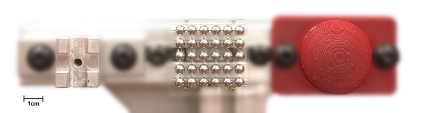
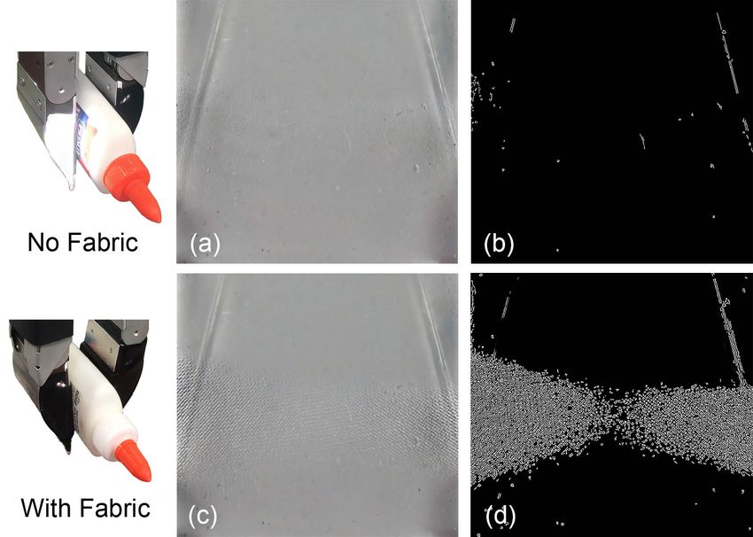
Fig. 2.   Tactile imprints. From left to right: The MCube Lab’s logo, 80/20 aluminum extrusion, a PCB, a screw, a Lego brick, and a key.

                                                                                 Instead of measuring force, some vision-based tactile
                                                                              sensors focus on measuring geometry, such as edges, texture
                                                                              or 3D shape of the contact surface. Ferrier and Brockett [11]
                                                                              proposed an algorithm to reconstruct the 3D surface by
                                                                              analyzing the distribution of the deformation of a set of
                                                                              markers on a tactile sensor. This principle has inspired
                                                                              several other contributions. The TacTip sensor [2] uses a
                                                                              similar principle to detect edges and estimate the rough
                                                                              3D geometry of the contact surface. Mounted on a GR2
Fig. 3. GelSlim finger. Pointed adaptation of the GelSight sensor featuring
a larger 50mm × 50mm sensor pad and strong, slim construction.                gripper, the sensor gave helpful feedback when reorienting
                                                                              a cylindrical object in hand [12]. Yamaguchi [13] built a
                                                                              tactile sensor with a clear silicone gel that can be mounted
Fingers must be compact and, when possible, pointed to                        on a Baxter hand. Unlike the previous sensors, Yamaguchi’s
squeeze between target and clutter (Fig. 3). To make use                      also captures the local color and shape information since the
of learning approaches, tactile sensors must also be resilient                sensing region is transparent. The sensor was used to detect
to the wear and tear from long experimental sessions which                    slip and estimate contact force.
often yield unexpected collisions. Finally, sensor calibration
and signal conditioning are key to the consistency of tactile                 B. GelSight sensors
feedback as the sensor’s physical components decay.                              The GelSight sensor is a vision-based tactile sensor that
                                                                              measures the 2D texture and 3D topography of the contact
                        II. R ELATED W ORK                                    surface. It utilizes a piece of elastomeric gel with an opaque
                                                                              coating as the sensing surface, and a webcam above the gel to
   The body of literature on tactile sensing technologies is
                                                                              capture contact deformation from changes in lighting contrast
large [1], [8]. Here we discuss relevant works related to
                                                                              as reflected by the opaque coating. The gel is illuminated
the technologies used by the proposed sensor: vision-based
                                                                              by color LEDs with inclined angles and different directions.
tactile sensors and GelSight sensors.
                                                                              The resulting colored shading can be used to reconstruct the
                                                                              3D geometry of the gel deformation. The original, larger
A. Vision-based tactile sensors
                                                                              GelSight sensor [14], [15] was designed to measure the
   Cameras provide high-spatial-resolution 2D signals with-                   3D topography of the contact surface with micrometer-level
out the need for many wires. Their sensing field and working                  spatial resolution. Li et al. [3] designed a cuboid fingertip
distance can also be tuned with an optical lens. For these                    version that could be integrated in a robot finger. Li’s sensor
reasons, cameras are an interesting alternative to several other              has a 1×1 cm2 sensing area, and can measure fine 2D texture
sensing technologies, which tend to have higher temporal                      and coarse 3D information. A new version of the GelSight
bandwidth but more limited spatial resolution.                                sensor was more recently proposed by Dong et al. [4] to
   Ohka et al. [9] designed an early vision-based tactile                     improve 3D geometry measurements and standardize the
sensor. It is comprised of a flat rubber sheet, an acrylic plate              fabrication process. A detailed review of different versions
and a CCD camera to measure three-dimensional force. The                      of GelSight sensors can be found in [16].
prototyped sensor, however, was too large to be realistically                    GelSight-like sensors with rich 2D and 3D information
integrated in a practical end-effector. GelForce [10], a tactile              have been successfully applied in robotic manipulation. Li et
sensor shaped like a human finger, used a camera to track                     al. [3] used GelSight’s localization capabilities to insert a
two layers of dots on the sensor surface to measure both the                  USB connector, where the sensor used the texture of the
magnitude and direction of an applied force.                                  characteristic USB logo to guide the insertion. Izatt et al. [17]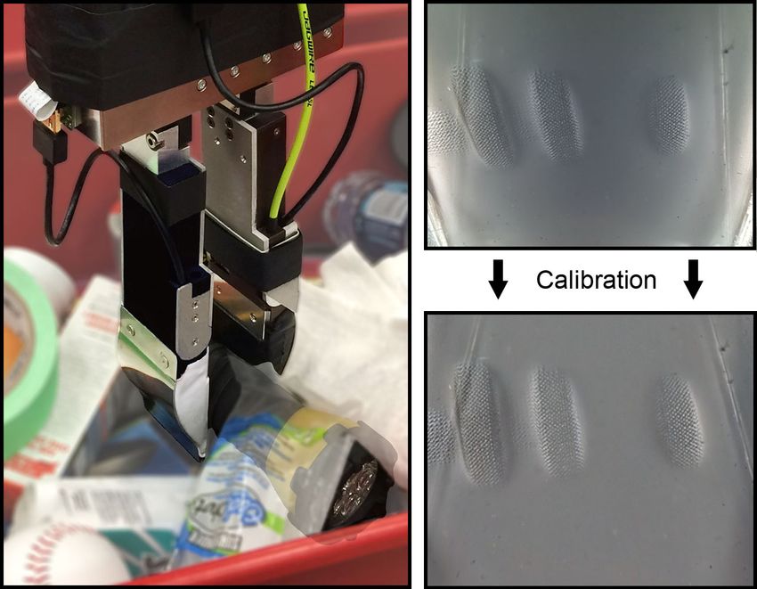
elements depends on the specific requirements of the sensor.
                                                                               Typically, for ease of manufacturing and optical simplicity,
                                                                               the camera’s optical axis is normal to the gel (left of Fig. 4).
                                                                               To reproduce 3D using photometric techniques [15], at least
                                                                               three colors of light must be directed across the gel from
                                                                               different directions.
                                                                                  Both of these geometric constraints, the camera placement
                                                                               and the illumination path, are counterproductive to slim robot
                                                                               finger integrations, and existing sensor implementations are
                                                                               cuboid. In most manipulation applications, successful grasp-
                                                                               ing requires fingers with the following qualities:
                                                                                  • Compactness allows fingers to singulate objects from
                                                                                    clutter by squeezing between them or separating them
                                                                                    from the environment.
                                                                                  • Uniform Illumination makes sensor output consistent
Fig. 4. The construction of a GelSight sensor. A general integration of a           across as much of the gel pad as possible.
GelSight sensor in a robot finger requires three components: camera, light,
                                                                                  • Large Sensor Area extends the area of the tactile cues,
and gel, in particular arrangement. Li’s original fingertip schematic [3] is
shown at left with our GelSlim at right.                                            both where there is and where there is not contact.
                                                                                    This can provide a better knowledge of the state of the
explored the use of the 3D point cloud measured by a                                grasped object and, ultimately, enhanced controllability.
                                                                                  • Durability affords signal stability, necessary for the
GelSight sensor in a state estimation filter to find the pose of
a grasped object in a peg-in-hole task. Dong et al. [4] used                        time-span of the sensor. This is especially important for
the GelSight sensor to detect slip from variations in the 2D                        data-driven techniques that build models from experi-
texture of the contact surface in a robot picking task. The 2D                      ence.
image structure of the output from a GelSight sensor makes                        In this paper we propose a redesign of the form, materials,
it a good fit for deep learning architectures. GelSight sensors                and processing of the GelSight sensor to turn it into a
have also been used to estimate grasp quality [18].                            GelSight finger, yielding a more useful finger shape with
                                                                               a more consistent and calibrated output (right of Fig. 4).
C. Durability of tactile sensors                                               The following sections describe the geometric and optical
   Frictional wear is an issue intrinsic to tactile sensors. Con-              tradeoffs in its design (Section IV), as well as the process to
tact forces and torques during manipulation are significant                    calibrate and evaluate it (Section V).
and can be harmful to both the sensor surface and its inner                                   IV. D ESIGN AND FABRICATION
structure. Vision-based tactile sensors are especially sensitive
to frictional wear, since they rely on the deformation of a soft                  To realize the design goals in Section III, we propose the
surface for their sensitivity. These sensors commonly use                      following changes to a standard design of a vision-based
some form of soft silicone gel, rubber or other soft material                  GelSight-like sensor: 1) Photometric stereo for 3D recon-
as a sensing surface [10], [19], [13], [4].                                    struction requires precise illumination. Instead, we focus on
   To enhance the durability of the sensor surface, researchers
have investigated using protective skins such as plastic [13],
or making the sensing layer easier to replace by involving
3D printing techniques with soft material [19].
   Another mechanical weakness of vision-based tactile sen-
sors is the adhesion between the soft sensing layer and its
stronger supporting layer. Most sensors discussed above use
either silicone tape or rely on the adhesive property of the
silicone rubber, which can be insufficient under practical
shear forces involved in picking and lifting objects. The wear
effects on these sensors are especially relevant if one attempts
to use them in a data-driven/learning context [13], [18].
   Durability is key to the practicality of a tactile sensor;
however, none of the above provide quantitative analysis of
their sensor’s durability over usage.
                        III. D ESIGN G OALS
  In a typical GelSight-like sensor, a clear gel with an                       Fig. 5. Texture in the sensor fabric skin improves signal strength.
opaque outer membrane is illuminated by a light source and                     When an object with no texture is grasped against the gel with no fabric,
                                                                               signal is very low (a-b). The signal improves with textured fabric skin (c-d).
captured by a camera (Fig. 4). The position of each of these                   The difference stands out well when processed with Canny edge detection.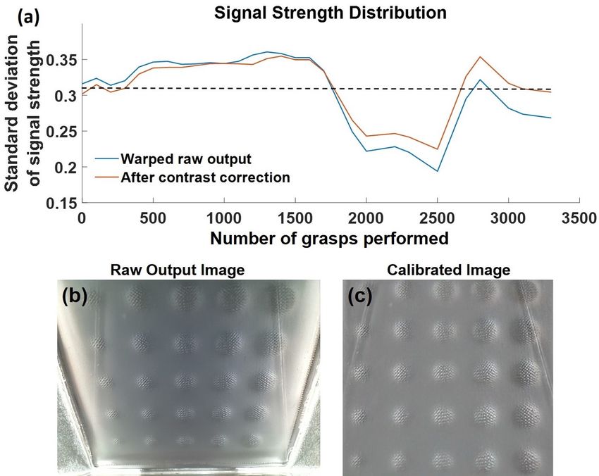
Fig. 6. The design space of a single-reflection GelSight sensor. Based
on the camera’s depth of field and viewing angle, it will lie at some distance
away from the gel. These parameters, along with mirror and camera angles,
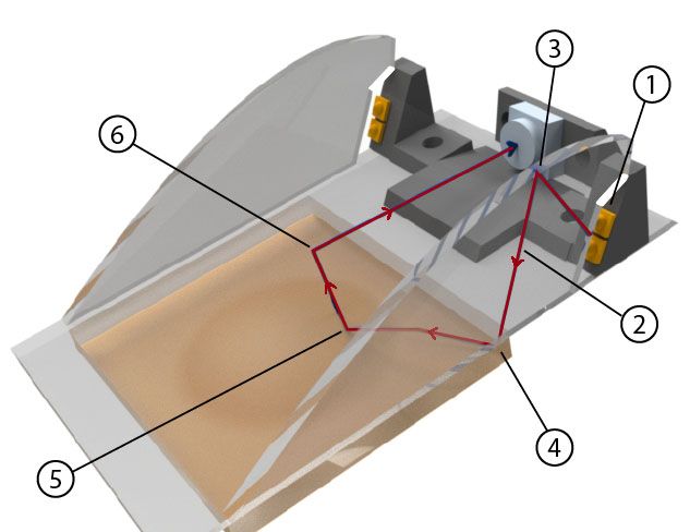
determine the thickness of the finger and the size of the gel pad. The virtual Fig. 7. The journey of a light ray through the finger. The red line
camera created by the mirror is drawn for visualization purposes. denoting the light ray is: 1) Emitted by two compact, high-powered LEDs on
each side. 2) Routed internal to acrylic guides via total internal reflection. 3)
Redistributed to be parallel and bounced toward the gel pad by a parabolic
recovering texture and contact surface, which will allow more mirror. 4) Reflected 90◦ on a mirror surface to graze across the gel. 5)
Reflected up by an object touching the gel. 6) Reflected to the camera by
compact light-camera arrangements. 2) The softness of the a flat mirror (not shown in the figure).
gel plays a role in the resolution of the sensor, but is also
damaging to its life span. We will achieve higher durability
by protecting the softest component of the finger, the gel, L · cos(β − Φ2 − 2α)
with textured fabric. 3) Finally, we will improve the finger’s h= , (1)
cos( Φ2 − β + α)
compactness, illumination uniformity, and sensor pad size
with a complete redesign of the sensor optics. where Φ is the camera’s field of view, α is mirror angle, β is
the camera angle relative to the base, and L is the length of
A. Gel Materials Selection the gel. L is given by the following equation and also relies
on the disparity between the shortest and longest light path
A GelSight sensor’s gel must be elastomeric, optically from the camera (depth of field):
clear, soft, and resilient. Gel hardness represents a tradeoff
(a − b) · sin Φ
between spatial resolution and strength. Maximum sensitivity L= . (2)
and resolution is only possible when gels are very soft, 2 sin Φ2 · sin (β − 2α)
but their softness yields two major drawbacks: low tensile Together, the design requirements h and L, vary with
strength and greater viscoelasticity. Given our application’s the design variables, α and β , and are constrained by the
lesser need for spatial resolution, we make use of slightly camera’s depth of field: (a − b) and viewing angle: Φ. These
harder, more resilient gels compared to other Gelsight sen- design constraints ensure that both near and far edges given
sors [3], [4]. Our final gel formulation is a two-part silicone by (2) are in focus and that the gel is maximally sized and
(XP-565 from Silicones Inc.) mixed in a 15:1 ratio of parts the finger is minimally thick.
A to B. The outer surface of our gel is coated with a specular
C. Optical Path: Photons From Source, to Gel, to Camera
silicone paint using a process developed by Yuan et al. [16].
The surface is covered with a stretchy, loose-weave fabric Our method of illuminating the gel makes three major
to prevent damage to the gel while increasing signal strength. improvements relative to previous sensors: a slimmer finger
Signal strength is proportional to deformation due to pressure tip, more even illumination, and a larger gel pad. Much like
on gel surface. Because the patterned texture of the fabric Li did in his original GelSight finger design [3], we use
lowers the contact area between object and gel, pressure is acrylic wave guides to move light throughout the sensor
increased to the point where the sensor can detect the contact with fine control over the angle of incidence across the gel
patch of flat objects pressed against the flat gel (Fig. 5). (Fig. 7). However, our design moves the LEDs used for
illumination farther back in the finger by using an additional
reflection, thus allowing our finger to be slimmer at the tip.
B. Sensor Geometry Design Space
The light cast on the gel originates from a pair of high-
We change the sensor’s form factor by using a mirror to powered, neutral white, surface-mount LEDs (OSLON SSL
reflect the gel image back to the camera. This allows us 80) on each side of the finger. Light rays stay inside
to have a larger sensor pad by placing the camera farther the acrylic wave guide due to total internal reflection by
away while also keeping the finger comparatively thin. A the difference in refractive index between acrylic and air.
major component of finger thickness is the optical region Optimally, light rays would be emitted parallel so as to not
with thickness h shown in Fig. 6, which is given by the lose intensity as light is cast across the gel. However, light
trigonometric relation: emitters are usually point sources. A line of LEDs, as in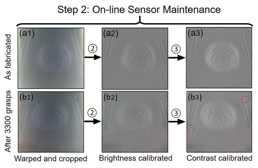
Li’s sensor, helps to evenly distribute illumination across       extended the camera’s fragile ribbon cable by first adapting it
one dimension while intensity decays across the length of         to an HDMI cable inside the finger, then passing that HDMI
the sensor.                                                       cable along the kinematic chain of the robot. Extending the
   Our approach uses a parabolic reflection (Step 3 in Fig. 7)    camera this way allows us to make it up to several meters
to ensure that light rays entering the gel pad are close to       long, mechanically and electrically protect the contacts, and
parallel. The two small LEDs are approximated as a single         route power to the LEDs through the same cable.
point source and placed at the parabola’s focus. Parallel light      The final integration of the sensor in our robot finger also
rays bounce across the gel via a hard 90◦ reflection. Hard        features a rotating joint to change the angle of the finger
reflections through acrylic wave guides are accomplished by       tip relative to the rest of the finger body. This movement
painting those surfaces with mirror finish paint.                 does not affect the optical system and allows us to more
   When an object makes contact with the fabric over the          effectively grasp a variety of objects in clutter.
gel pad, it creates a pattern of light and dark spots as the         There are numerous ways to continue improving the
specular gel interacts with the grazing light. This image         sensor’s durability and simplify the sensor’s fabrication pro-
of light and dark spots is transmitted back to the camera         cess. For example, while the finger is slimmer, it is not
off a front-surface glass mirror. The camera (Raspberry Pi        smaller. It will be a challenge to make integrations sized
Spy Camera) was chosen for its small size, low price, high        for smaller robots due to camera field of view and depth of
framerate/resolution, and good depth of field.                    field constraints. Additionally, our finger has an un-sensed,
                                                                  rigid tip that is less than ideal for two reasons: it is the
D. Lessons Learned
                                                                  part of the finger with the richest contact information, and
   For robotic system integrators, or those interested in         its rigidity negatively impacts the sensor’s durability. To
designing their own GelSight sensors, the following is a          decrease contact forces applied due to this rigidity, we will
collection of small but important lessons we learned:             add compliance to the finger-sensor system.
   1) Mirror: Back surface mirrors create a “double image”
      from reflections off front and back surfaces especially     E. Gel Durability Failures
      at the reflection angles we use in our sensor. Glass           We experimented with several ways to protect the gel
      front surface mirrors give a sharper image.                 surface before selecting a fabric skin. Most non-silicone
   2) Clean acrylic: Even finger oils on the surface of a         coatings will not stick to the silicone bulk, so we tested
      wave guide can interrupt total internal reflection. Clean   various types of filled and non-filled silicones. Because this
      acrylic obtains maximum illumination efficiency.            skin coats the outside, using filled (tougher, non-transparent)
   3) Laser cut acrylic: Acrylic pieces cut by laser exhibit      silicones is an option. One thing to note is that thickness
      stress cracking at edges after contacting solvents from     added outside of the specular paint increases impedance of
      glue or mirror paint. Cracks break the optical continu-     the gel, thus decreasing resolution. To deposit a thin layer
      ity in the substrate and ruin the guide. Stresses can be    onto the bulk, we diluted filled, flowable silicone adhesive
      relieved by annealing first.                                with NOVOCS silicone thinner from Smooth-On Inc. We
   4) LED choice: This LED was chosen for its high                found that using solvent in proportions greater than 2:1
      luminous efficacy (103 lm/W), compactness (3mm ×            (solvent:silicone) caused the gel to wrinkle (possibly because
      3mm), and small viewing angle (80◦ ). Small viewing         solvent diffused into the gel and caused expansion).
      angle directs more light into the thin wave guide.             Using a non-solvent approach to deposit thin layers like
   5) Gel paint type: From our experience in this config-         spin coating is promising, but we did not explore this path.
      uration, semi-specular gel coating provides a higher-       Furthermore, thin silicone coatings often rubbed off after a
      contrast signal than lambertian gel coatings. Yuan et       few hundred grasps signaling that they did not adhere to the
      al. [16] describe the different types of coatings and       gel surface effectively. Plasma pre-treatment of the silicone
      how to manufacture them.                                    surface could more effectively bond substrate and coating,
   6) Affixing silicone gel: When affixing the silicone gel       but we were unable to explore this route.
      to the substrate, most adhesives we tried made the
      images hazy or did not acceptably adhere to either                           V. S ENSOR C ALIBRATION
      the silicone or substrate. We found that Adhesives             The consistency of sensor output is key for sensor usabil-
      Research ARclear 93495 works well. Our gel-substrate        ity. The raw image from a GelSlim sensor right after fabri-
      bond is also stronger than other gel-based sensors          cation has two intrinsic issues: non-uniform illumination and
      because of its comparatively large contact area.            a strong perspective distortion. In addition, the sensor image
Some integration lessons revolve around the use of a Rasp-        stream may change during use due to small deformations
berry Pi spy camera. It enables a very high data-rate but         of the hardware, compression of the gel, or camera shutter
requires a 15-pin Camera Serial Interface (CSI) connection        speed fluctuations. To improve the consistency of the signal
with the Raspberry Pi. Since the GelSlim sensor was de-           we introduce a two-step calibration process, illustrated in
signed for use on a robotic system where movement and             Fig. 8 and Fig. 9.
contact are part of normal operation, the processor (Rasp-        Calibration Step 1. Manufacture correction. After fabri-
berry Pi) is placed away from the robot manipulator. We           cation, the sensor signal can vary with differences in camera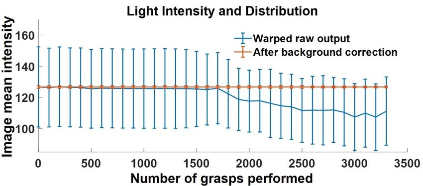
Fig. 8. Calibration Step 1 (manufacture correction): capture raw image        Fig. 9.      Calibration Step 2 (on-line sensor maintenance): apply
(a1) against a calibration pattern with four rectangles and a non-contact     transformation T to start from a warped and cropped image (a1) and (b1);
image (b1); calculate the “transform matrix” T according to image (a1);       operation 2 uses the non-contact image from step 1 and adds constant M
do operation 1 “image warping and cropping” to image (a1) and (b1)            to calibrate the image brightness (a2) and (b2); operation 3 performs a
and get (a2) and (b2); apply Gaussian filter to (b2) to get “background       local contrast adjustment (a3) and (b3). All the images show the imprint of
illumination” B ; do operation 2 to (a2) and get the calibrated image (a3);   the calibration “dome” after fabrication and 3300 grasps. The red circles in
record the “mean value” M of image (b2) as brightness reference.              b(3) highlight the region where the gel wears out after 3300 grasps.

perspective and illumination intensity. To correct for camera
perspective, we capture a tactile imprint in Fig. 8 (a1) against
a calibration pattern with four flat squares (Fig. 10 left). With
the distance between the outer edges of the four squares,
we estimate the perspective transformation matrix T that
allows us to warp the image to a normal perspective and                       Fig. 10. Three tactile profiles to calibrate the sensor. From left to right: A
                                                                              rectangle with sharp corners, a ball-bearing array, and a 3D printed dome.
crop the boundaries. The contact surface information in
the warped image (Fig. 8 (a2)) is more user-friendly. We
assume the perspective camera matrix remains constant, so                     A. Metric I: Light Intensity and Distribution
the manufacture calibration is done only once.
   We correct for non-homogenous illumination by estimat-                        The light intensity and distribution are the mean and
ing the illumination distribution of the background B using                   standard deviation of the light intensity in a non-contact
a strong Gaussian filter on a non-contact warped image                        image. The light intensity distribution in the gel is influenced
(Fig. 8 (b2)). The resulting image, after subtracting the non-                by the condition of the light source, the consistency of the
uniform illumination background (Fig. 8 (a3)), is visually                    optical path and the homogeneity of the paint of the gel.
more homogeneous. In addition, we record the mean value                       The three factors can change due to wear. Fig. 11 shows
of the warped non-contact image M as brightness reference                     their evolution over grasps before (blue) and after (red)
for future use.                                                               background illumination correction. The standard deviations
                                                                              are shown as error bars. The blue curve (raw output from the
Calibration Step 2. On-line Sensor Maintenance. The aim                       sensor) shows that the mean brightness of the image drops
of the second calibration step is to keep the sensor output                   slowly over time, especially after around 1750 grasps. This is
consistent over time. We define four metrics to evaluate the                  likely due to slight damage of the optical path. The variation
temporal consistency of the 2D signal: Light intensity and                    of the image brightness over space decreases slightly, which
distribution, Signal strength, Signal strength distribution and               is likely caused by the fact that the bright two sides of the
Gel condition. In the following subsection, we will describe                  image get darker and more similar to the center region. Fig. 9
and evaluate these metrics in detail.                                         shows an example of the decrease in illumination before (a1)
   We will make use of the calibration targets in Fig. 10 to                  and after (b1) 3300 grasps.
track the signal quality, including a ball-bearing array and a                   We compensate for the changes in light intensity by sub-
3D printed dome. We conduct over 3300 aggressive grasp-                       tracting the background and adding a constant M (brightness
lift-vibrate experiments on several daily objects with two                    reference from step one) to the whole image. The background
GelSlim fingers on a WSG-50 gripper attached to an ABB                        illumination is obtained from the Gaussian filtered non-
IRB 1600ID robotic arm. We take a tactile imprint of the two                  contact image at that point. The mean and variance of
calibration targets every 100 grasps. The data presented in the               the corrected images, shown in red in Fig. 11, are more
following sections were gathered with a single prototype and                  consistent. Fig. 9 shows an example of the improvement after
are for the purposes of evaluating sensor durability trends.                  3300 grasps.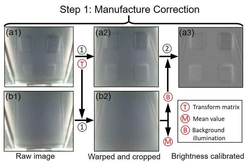
Fig. 11.   Evolution of the light intensity distribution.

B. Metric II: Signal Strength
   The signal strength S is a measure of the dynamic range of
the tactile image under contact. It is intuitively the brightness
and contrast of a contact patch, and we define it as:
                                   2µ    σ
                    S = H(σ − m)(      + ),                  (3)       Fig. 13. (a) The evolution of signal strength distribution (b) The raw output
                                  255 n                                of “ball array” calibration image (c) The calibrated “ball array” calibration
where µ is the mean and σ the standard deviation of the im-            image.
age intensity in the contact region, and H(x) is the Heaviside
step function. H(σ − m) means that if the standard deviation           equalization together according to the local background
is smaller than m, signal strength is 0. Experimentally, we            illumination. The two images after the whole calibration are
set m to 5, and n, the standard deviation normalizer, to 30.           shown in Fig. 9 (a3) and (b3). The signal strength after
   Maintaining a consistent signal strength during use is              calibrating illumination and contrast (Fig. 12 in red) shows
one of the most important factors for the type of contact              better consistency during usage.
information we can extract in a vision-based tactile sensor. In        C. Metric III: Signal Strength Distribution
a GelSlim sensor, signal strength is affected by the elasticity
of the gel, which degrades after use.                                     The force distribution after grasping an object is non-
   We track the signal strength during grasps by using the             uniform across the gel. During regular use, the center and
“dome” calibration pattern designed to yield a single contact          distal regions of the gel are more likely to be contacted
patch. Fig. 12 shows its evolution. The blue curve (from raw           during grasping, which puts more wear on the gel in those
output) shows a distinct drop of the signal strength after 1750        areas. This phenomenon results in a non-uniform degradation
grasps. The brightness decrease described in the previous              of the signal strength. To quantify this phenomenon, we
subsection is one of the key reasons.                                  extract the signal strength of each pressed region from the
   The signal strength can be enhanced by increasing both              “ball array” calibration images taken every 100 grasps (see
the contrast and brightness of the image. The brightness ad-           Fig. 13 (b) before and (c) after calibration). We use the
justment done after fabrication improves the signal strength,          standard deviation of the 5 × 5 array of signal strengths to
shown in green in Fig. 12. However, the image with bright-             represent the signal strength distribution, and compensate for
ness correction after 3300 grasps shown in Fig. 9 (b2) still           variations by increasing the contrast non-uniformly in the
has decreased contrast.                                                decreased regions.
   To enhance the image contrast according to the illumi-                 Fig. 13 shows signal strength distribution before and after
nation, we perform adaptive histogram equalization to the              calibration in (blue) and (red) respectively. The red curve
image, which increases the contrast on the whole image,                shows some marginal improvement in the consistency over
and then fuses the images with and without histogram                   usage. The sudden increase of the curve after 2500 grasps
                                                                       is caused by the change in light distribution likely due to
                                                                       damage of the optical path by an especially aggressive grasp.
                                                                       D. Metric IV: Gel Condition
                                                                          The sensor’s soft gel is covered by a textured fabric skin
                                                                       for protection. Experimentally, this significantly increases the
                                                                       resilience to wear. However, the reflective paint layer of the
                                                                       gel may still wear out after use. Since the specular paint acts
                                                                       as a reflection surface, the regions of the gel with damaged
                                                                       paint do not respond to contact signal and are seen as black
                                                                       pixels, which we call dead pixels.
                                                                          We define the gel condition as the percentage of dead
Fig. 12.   The change of signal strength across the number of grasps   pixels in the image. Fig. 14 shows the evolution of the
performed.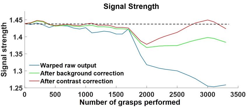
number of dead pixels over the course of 3000 grasps. Only a         solution is just one path forward, we beilive that high-
small amount of pixels (less than 0.06%, around 170 pixels)          resolution tactile sensors hold particular promise.
are damaged, highlighted with red circles in Fig. 9 (b3).                                         R EFERENCES
Sparse dead pixels can be ignored or fixed with interpolation,
                                                                      [1] Z. Kappassov, J.-A. Corrales, and V. Perdereau, “Tactile sensing in
but a large number of clustered dead pixels can be solved                 dexterous robot hands,” Robotics and Autonomous Systems, vol. 74,
only by replacing the gel.                                                pp. 195–220, 2015.
                                                                      [2] C. Chorley, C. Melhuish, T. Pipe, and J. Rossiter, “Development of a
                                                                          tactile sensor based on biologically inspired edge encoding,” in ICAR.
                                                                          IEEE, 2009, pp. 1–6.
                                                                      [3] R. Li, R. Platt, W. Yuan, A. ten Pas, N. Roscup, M. A. Srinivasan,
                                                                          and E. Adelson, “Localization and manipulation of small parts using
                                                                          GelSight tactile sensing,” in IROS. IEEE, 2014, pp. 3988–3993.
                                                                      [4] S. Dong, W. Yuan, and E. Adelson, “Improved GelSight tactile sensor
                                                                          for measuring geometry and slip,” IROS, 2017.
                                                                      [5] A. Zeng, K.-T. Yu, S. Song, D. Suo, E. Walker, A. Rodriguez, and
                                                                          J. Xiao, “Multi-view Self-Supervised Deep Learning for 6D Pose
                                                                          Estimation in the Amazon Picking Challenge,” in ICRA. IEEE, 2017,
                                                                          pp. 1386–1383.
                                                                      [6] A. Zeng, S. Song, K.-T. Yu, E. Donlon, F. Hogan, M. Bauza, D. Ma,
              Fig. 14.   Evolution of the gel condition.                  O. Taylor, M. Liu, E. Romo, N. Fazeli, F. Alet, N. Chavan-Dafle,
                                                                          R. Holladay, I. Morona, P. Q. Nair, D. Green, I. Taylor, W. Liu,
                                                                          T. Funkhouser, and A. Rodriguez, “Robotic pick-and-place of novel
         VI. C ONCLUSIONS AND F UTURE W ORK                               objects in clutter with multi-affordance grasping and cross-domain
                                                                          image matching,” in ICRA. IEEE, 2018.
   In this paper, we present a compact integration of a visual-       [7] N. Correll, K. Bekris, D. Berenson, O. Brock, A. Causo, K. Hauser,
                                                                          K. Okada, A. Rodriguez, J. Romano, and P. Wurman, “Analysis and
tactile sensor in a robotic phalange. Our design features: a gel          observations from the first amazon picking challenge,” T-ASE, vol. 15,
covered with a textured fabric skin that improves durability              no. 1, pp. 172–188, 2018.
and contact signal strength; a compact integration of the             [8] R. S. Dahiya, G. Metta, M. Valle, and G. Sandini, “Tactile sensing
                                                                          from humans to humanoids,” IEEE T-RO, vol. 26, no. 1, pp. 1–20,
GelSight sensor optics; and an improved illumination over                 2010.
a larger tactile area. Despite the improved wear resistance,          [9] M. Ohka, Y. Mitsuya, K. Hattori, and I. Higashioka, “Data conversion
the sensor still ages over use. We propose four metrics to                capability of optical tactile sensor featuring an array of pyramidal
                                                                          projections,” in MFI. IEEE, 1996, pp. 573–580.
track this aging process and create a calibration framework          [10] K. Kamiyama, K. Vlack, T. Mizota, H. Kajimoto, K. Kawakami,
to regularize sensor output over time. We show that, while                and S. Tachi, “Vision-based sensor for real-time measuring of surface
the sensor degrades minimally over the course of several                  traction fields,” CG&A, vol. 25, no. 1, pp. 68–75, 2005.
                                                                     [11] N. J. Ferrier and R. W. Brockett, “Reconstructing the shape of a
thousand grasps, the digital calibration procedure is able to             deformable membrane from image data,” IJRR, vol. 19, no. 9, pp.
condition the sensor output to improve its usable life-span.              795–816, 2000.
                                                                     [12] B. Ward-Cherrier, N. Rojas, and N. F. Lepora, “Model-free precise
Sensor Functionality. The sensor outputs images of tactile                in-hand manipulation with a 3d-printed tactile gripper,” RA-L, vol. 2,
imprints that encode shape and texture of the object at                   no. 4, pp. 2056–2063, 2017.
contact. For example, contact geometry in pixel space could          [13] A. Yamaguchi and C. G. Atkeson, “Combining finger vision and
                                                                          optical tactile sensing: Reducing and handling errors while cutting
be used in combination with knowledge of grasping force and               vegetables,” in Humanoids. IEEE, 2016, pp. 1045–1051.
gel material properties to infer 3D local object geometry. If        [14] M. K. Johnson and E. Adelson, “Retrographic sensing for the mea-
markers are placed on the gel surface, marker flow can be                 surement of surface texture and shape,” in CVPR. IEEE, 2009, pp.
                                                                          1070–1077.
used to estimate object hardness [20] or shear forces [21].          [15] M. K. Johnson, F. Cole, A. Raj, and E. H. Adelson, “Microgeometry
These quantities, as well as the sensor’s calibrated image                capture using an elastomeric sensor,” in TOG, vol. 30, no. 4. ACM,
output, can be used directly in model-based or learning-                  2011, p. 46.
                                                                     [16] W. Yuan, S. Dong, and E. H. Adelson, “GelSight: High-resolution
based approaches to robot grasping and manipulation. This                 robot tactile sensors for estimating geometry and force,” Sensors,
information could be used to track object pose, inform a                  vol. 17, no. 12, p. 2762, 2017.
data-driven classifier to predict grasp stability, or as real-time   [17] G. Izatt, G. Mirano, E. Adelson, and R. Tedrake, “Tracking objects
                                                                          with point clouds from vision and touch,” in ICRA. IEEE, 2017.
observations in a closed-loop regrasp policy [22].                   [18] R. Calandra, A. Owens, M. Upadhyaya, W. Yuan, J. Lin, E. H.
Applications in robotic dexterity. We anticipate that Gel-                Adelson, and S. Levine, “The feeling of success: Does touch sensing
                                                                          help predict grasp outcomes?” arXiv preprint arXiv:1710.05512, 2017.
Slim’s unique form factor will facilitate the use of these           [19] B. Ward-Cherrier, N. Pestell, L. Cramphorn, B. Winstone, M. E.
sensing modalities in a wide variety of applications – espe-              Giannaccini, J. Rossiter, and N. F. Lepora, “The tactip family: Soft
cially in cluttered scenarios where visual feedback is lacking,           optical tactile sensors with 3D-printed biomimetic morphologies,” Soft
                                                                          Robotics, 2018.
where access is limited, or where difficult to observe contact       [20] W. Yuan, M. A. Srinivasan, and E. Adelson, “Estimating object
forces play a key role. We are especially interested in using             hardness with a gelsight touch sensor,” in Intelligent Robots and
real-time contact geometry and force information to monitor               Systems (IROS 2016), 2016 IEEE/RSJ International Conference on.
                                                                          IEEE, 2016.
and control tasks that require in-hand dexterity and reactivity      [21] W. Yuan, R. Li, M. A. Srinivasan, and E. H. Adelson, “Measurement
such as picking a tool in a functional grasp and then using               of shear and slip with a gelsight tactile sensor,” in ICRA. IEEE, 2015,
it or grasping a nut and screwing it on a bolt. Ultimately,               pp. 304–311.
                                                                     [22] F. R. Hogan, M. Bauza, O. Canal, E. Donlon, and A. Rodriguez, “Tac-
these contact-rich tasks can only be robustly tackled with                tile regrasp: Grasp adjustments via simulated tactile transformations,”
tight integration of sensing and control. While the presented             arXiv preprint arXiv:1803.01940, 2018.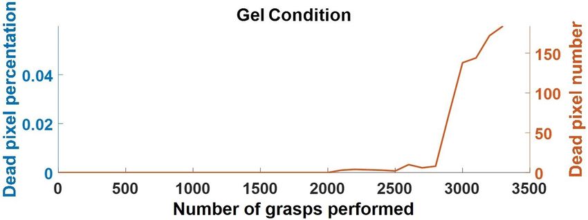
You can also read