JOURNAL OF FLUIDS AND STRUCTURES - LADHYX
←
→
Page content transcription
If your browser does not render page correctly, please read the page content below
Journal of Fluids and Structures 80 (2018) 77–93

                                                      Contents lists available at ScienceDirect

                                             Journal of Fluids and Structures
                                                 journal homepage: www.elsevier.com/locate/jfs

Vortex-induced vibrations of cylinders bent by the flow
Tristan Leclercq *, Emmanuel de Langre
Department of Mechanics, LadHyX, CNRS, École Polytechnique, 91128 Palaiseau, France

article               info                            a b s t r a c t
Article history:                                      Flexible cylinders exposed to transverse flows may undergo transverse vortex-induced
Received 13 November 2017                             vibrations due to the oscillating lift force imposed by their wake. But the drag on such
Received in revised form 6 February 2018              structures often leads to large in-line deflections that may significantly affect the dynamics
Accepted 14 March 2018
                                                      through the combined effects of the curvature-induced tension, the local inclination of the
                                                      cylinder, the non-uniformity of the normal flow profile, and the large axial flow component.
                                                      In this paper, we investigate the consequences of flow-induced bending on the vortex-
Keywords:
Vortex-induced vibrations                             induced dynamics of slender cantilever cylinders, by means of numerical simulations. We
Wake oscillator                                       combine a distributed wake oscillator approach to model the dynamics of the wake with
Curved cylinder                                       Lighthill’s large-amplitude elongated body theory to account for the effect of the axial flow
Linear stability analysis                             in the reactive (added mass) force. The use of such reduced order models facilitates the
                                                      identification of the physical mechanisms at play, including through the linear analysis of
                                                      the coupled fluid–structure system. We find that the primary consequence of flow-induced
                                                      bending is the inhibition of single mode lock-in, replaced by a multi-frequency response of
                                                      the structure, and the reduction of the vibration amplitude, as a result of the broadening
                                                      of the wake excitation spectrum and of the localization of the energy transfer due to the
                                                      variations induced in the normal flow profile. We also find that the curvature-induced
                                                      tension is of negligible influence, but that the axial flow component may on the other hand
                                                      significantly alter the dynamics owing to the destabilizing effect of the reactive force on
                                                      the structural modes.
                                                                                                             © 2018 Elsevier Ltd. All rights reserved.

1. Introduction

    The vortex-induced vibrations (VIVs) of slender cylindrical structures has been a prominent subject of research for many
years. Originally, a better understanding of this phenomenon was sought in the civil and marine engineering community
mostly because of the damage it may cause on a number of flow-exposed structures such as buildings, power transmission
lines, marine risers, towing cables, or mooring lines. For extensive reviews regarding VIVs, the reader is referred to
Williamson and Govardhan (2004), Sarpkaya (2004), Williamson and Govardhan (2008), Bearman (2011) and Wu et al.
(2012). More recently, a renewed interest for the VIVs has arisen from the potential they bear as an alternative source of
energy (Bernitsas et al., 2008).
    The large majority of existing studies focus on the VIVs of straight cylinders in a variety of configurations: rigid or
flexible, perpendicular to the flow or slanted, exposed to a uniform or a sheared flow. However, most of the off-shore
flexible structures such as those cited above are actually greatly deformed in the direction of the flow under the effect
of the free-stream. This configuration differs from the case of a straight cylinder on several aspects. First, the deflection in
the plane of the free-stream of a cylinder is responsible for a curvature-induced tension inside the structure. The tensioning

  *   Corresponding author.
      E-mail addresses: tristan.leclercq@polytechnique.edu (T. Leclercq), delangre@ladhyx.polytechnique.fr (E. de Langre).

https://doi.org/10.1016/j.jfluidstructs.2018.03.008
0889-9746/© 2018 Elsevier Ltd. All rights reserved.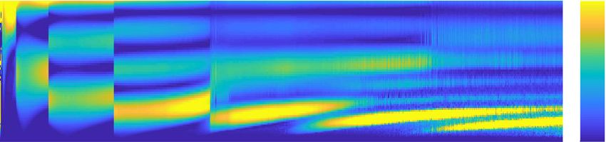
78                                 T. Leclercq, E. de Langre / Journal of Fluids and Structures 80 (2018) 77–93

of the cylinder may affect its natural frequencies, and consequently its dynamic response to the wake excitation. Secondly,
deflected structures are not locally perpendicular to the flow, which modifies the features of vortex shedding in the wake
and the associated forces on the structure. Besides, a curved structure experiences a spanwise variation of its angle with the
free-stream. Finally, the reconfiguration of the structure leads to a large axial component of the flow on the most inclined
portion of the structure that may even become dominant when the deflection is significant. The consequences of some of
these specificities have been individually studied, see for instance Srinil et al. (2009) and Srinil (2010) for the structural effect
of the curvature, Lucor and Karniadakis (2003), Facchinetti et al. (2004b), Franzini et al. (2009), Jain and Modarres-Sadeghi
(2013) and Bourguet et al. (2015) for the effect of the inclination, or Vandiver (1993), Chaplin et al. (2005), Trim et al. (2005),
Lucor et al. (2006), Violette et al. (2010) and Bourguet et al. (2013) for the effect of non-uniform normal flow profiles, but
their combined effects may lead to a significant alteration of the wake–structure interaction that has not yet been fully
investigated.
     As a first step towards the understanding of VIVs of bent cylinders, Miliou et al. (2007) and de Vecchi et al. (2008)
numerically explored the vortex shedding process in the wake of a rigid cylinder in the shape of a convex or concave
quarter of a ring, when the structure is respectively fixed or forced into an oscillatory motion. Building on these results, Assi
et al. (2014) and Seyed-Aghazadeh et al. (2015) experimentally investigated the free vibrations of similar structures and
found that the amplitude of the oscillations is much reduced compared to the straight configuration. Two studies provided
experimental observations regarding the VIVs of flexible structures about a curvy shape: the experimental work of Zhu et al.
(2016) considered the vibrations of a naturally concave-shaped cylinder subjected to a shear flow, while that of Morooka and
Tsukada (2013) tested a model riser deformed in the shape of a concave catenary under the effect of a uniform free-stream.
Finally, Bourguet et al. (2012, 2015) numerically investigated the VIVs of tensioned flexible beams respectively exposed
to a normal sheared flow and an inclined uniform flow. Both studies considered the influence of a small average in-line
deformation and noted the transition from a mono-frequency to a multi-frequency response associated with a modification
of the normal flow profile due to the bending. A reduction of the amplitude of the VIVs was also reported in Bourguet et al.
(2015). At this point however, a theoretical study is still missing to clarify the consequences of flow-induced bending on the
VIVs of slender cylinders in large deformations and identify the physical mechanisms at play. One may for instance wonder
how the bending-induced shear in the normal flow might impact the vibration spectrum, whether lock-in may or may not
still occur, or furthermore how the amplitude of vibration might be affected?
     But the flow-induced bending of the structure may have even more dramatic consequences. Indeed, slender structures in
axial flows are liable to a flutter instability (Datta and Gottenberg, 1975; Yadykin et al., 2001; Païdoussis et al., 2002; Semler et
al., 2002). This self-induced dynamics results from the destabilizing effect of the inviscid pressure forces associated with the
deformation of the structure in a free-stream with a significant axial component (Eloy et al., 2007; Singh et al., 2012a). When
a cylinder deflects in a transverse flow, the increasing spanwise component of the free-stream may thus be the cause of such
instability. More generally, the influence of the inviscid pressure forces on the structural modes may have consequences on
the vortex-induced dynamics even in a domain of the parameter space where the system does not flutter.
     The purpose of the present paper is to provide an analysis of the small-amplitude vibrations of slender cylinders bent by
the flow by means of reduced order models to identify the physical mechanisms at play. In particular, a formulation of the
inviscid pressure forces based on Lighthill’s large-amplitude elongated body theory (Lighthill, 1971) will be used to account
for the destabilizing effect of the axial component of the free-stream. We will also make use of a wake oscillator to describe
the lift resulting from vortex shedding. This class of models was originally derived to represent the dynamics of the free
wake behind a fixed structure (Birkhoff and Zarantonello, 1957; Bishop and Hassan, 1964), and they have been proved able to
capture some characteristic features of the vortex shedding mechanism, such as the formation of cells in shear flow (Noack et
al., 1991; Mathelin and de Langre, 2005). Such models have also been proved useful in qualitatively describing the physics of
VIVs when coupled with a structural oscillator (Hartlen and Currie, 1970; Skop and Balasubramanian, 1997; Balasubramanian
et al., 2000; Mukundan et al., 2009; Srinil and Zanganeh, 2012), and they have been validated against experimental and
numerical results (Violette et al., 2007). In this regard, the work of Facchinetti et al. (2004a) demonstrated that features such
as the boundaries of the lock-in range, the amplitude of the vibrations or the phase between the structure and the wake
are correctly predicted when a coupling term proportional to the structural acceleration is used. The subsequent work of
de Langre (2006) and Violette et al. (2010) further demonstrated that many features of the nonlinear limit-cycle dynamics
can be interpreted through the linear analysis of the coupled wake–structure oscillators.
     In Section 2, the model for the flow–structure interactions and its specific adaptations to the problem in question are
detailed. The consequences of the flow-induced bending on the VIVs are then discussed in Section 3 based on the results of
numerical simulations.

2. Model

2.1. Theoretical modelling

   We consider the model system represented on Fig. 1. A circular cylinder of length L, diameter D and mass per unit length
m is clamped perpendicular to a uniform and steady flow of velocity Uex of a fluid of density ρ . We assume the cylinder is
slender (D ≪ L) and we model it as an inextensible Euler–Bernoulli beam of bending stiffness EI (see more details about
the structural model in Appendix A.1). We note s the curvilinear coordinate along the span from the clamped end to the free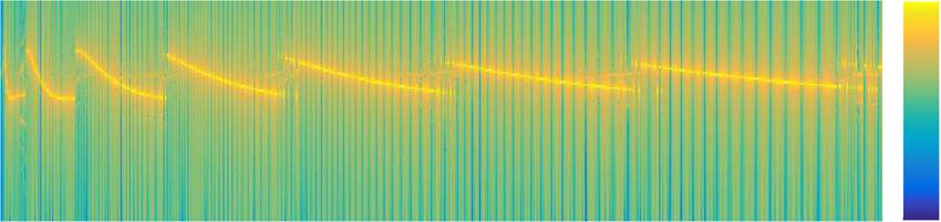
T. Leclercq, E. de Langre / Journal of Fluids and Structures 80 (2018) 77–93                                       79

Fig. 1. (a) Dimensions of the undeformed cylinder and centreline (broken line). (b) 3D view of the centreline of the vibrating cylinder, static deflection r0 (s)
(broken black line), fully deformed shape r(s, t) (solid grey line). The π -plane in grey indicates the surface upon which the vibration occurs. (c) Projection
of the deformation on the plane of static deflection (xz-plane). (d) Projection of the deformation on the surface of vibration (π -surface or sy-surface).

end, and r(s, t) the location of the centreline. In this paper we focus on the small-amplitude transverse oscillations so we
consider that the structure is primarily deflected in the xz-plane under the effect of the flow into a leading order configuration
r0 (s) (broken black line on Fig. 1, specifically shown on Fig. 1(c)). Vortex shedding in the wake of the bent structure is then
responsible for an oscillatory lift force in the y-direction that induces small-amplitude transverse vibrations (solid grey line
on Fig. 1, specifically shown on Fig. 1(d)) such that r(s, t) = r0 (s) + Y (s, t)ey .
    We disregard the influence of gravity and buoyancy, and we restrict our study to large Reynolds number flows so that
friction forces are neglected. Following Mukundan et al. (2009) and Violette et al. (2010), we model the effect of the fluid
as the combination of three load distributions along the span p = pam + pd + pw , where pam is the reactive or added mass
force, pd is the resistive drag due to flow separation in the plane of the cross-section, and pw is the oscillating lift force due to
the vorticity wake. The expressions of these forces involve the projections (Uτ , UN ) on the direction tangent to the structure
and on the plane normal to it, of the relative velocity between the cylinder and the fluid Urel = Ẏ ey − Uex = Uτ τ + UN N ,
where the overdot stands for time differentiation.
    Firstly, in the case of an elongated body such as those considered in this study, the expression of the added mass force
stemming from the pressure field associated with the potential component of the flow has originally been derived by Lighthill
(1971) for large-amplitude planar motions. Its extension to 3D deformations has been derived by Candelier et al. (2011) and
reads
                        [                                                    ]
                                                           1
        pam = −ma ∂t (UN N ) − ∂s (Uτ UN N ) +                 ∂s (UN2 τ )                                                                                   (1)
                                                           2

with the added mass ma = 1/4ρπ D2 . This expression differs from the usual added mass force used in VIV studies because
it is designed to account for the effects of the curvature as well as a large axial flow component. The additional terms
thus introduced cancel in the specific case of a straight structure so this choice is nonetheless consistent with the usual
expression used in previous works on the topic. On the other hand, this expression has been widely used in studies of the
flutter instability of slender beams in axial flow (Païdoussis, 1998; de Langre et al., 2007; Eloy et al., 2012; Singh et al., 2012b;
Michelin and Doaré, 2013).
    Secondly, following Taylor (1952), we express the resistive drag force as
              1
        pd = − ρ CD D|UN |UN N                                                                                                                               (2)
              2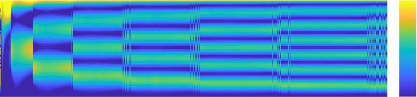
80                                                   T. Leclercq, E. de Langre / Journal of Fluids and Structures 80 (2018) 77–93

with CD the cross-section drag coefficient. Due to the transverse vibrations, this coefficient may be dynamically enhanced by
an amplitude-dependent factor classically of the order of 2 (Vandiver, 1983; Blevins, 1990; Chaplin et al., 2005). The exact
value of the drag coefficient should however have only a limited impact on the qualitative features of the VIVs. For the sake
of simplicity, we hereafter take CD = 2 for a vibrating cylinder (Blevins, 1990; Chaplin et al., 2005; Mathelin and de Langre,
2005). The resistive drag term is responsible for the leading order static deflection of the beam in the xz-plane (see Gosselin
et al., 2010; Leclercq and de Langre, 2016) and acts as hydrodynamic damping for the transverse vibrations.
    Finally, following Antoine et al. (2016) the local effect of vortex shedding is modelled as an oscillating lift force orthogonal
to the cylinder axis and to the component of the free-stream normal to the still cylinder
               1
      pw =         ρ CL0 DU 2 cos2 θ0 q ey                                                                                          (3)
               4
where the fixed cylinder lift coefficient CL0 is multiplied by a local magnification factor q(s, t) that satisfies a nonlinear Van
der Pol equation forced by the transverse acceleration of the structure
               (                        )                               (                        )2
                        St U                                                     St U                    Ÿ
      q̈ + ε       2π          cos θ0            2
                                                                            2π          cos θ0        q=A .
                                            (               )
                                                q − 1 q̇ +                                                                          (4)
                         D                                                        D                      D

We assume in this study the classical values St = 0.2, CL0 = 0.3 in the sub-critical range 300 < Re < 1.5 × 10⁵ (Blevins,
1990; Facchinetti et al., 2004a). Following Facchinetti et al. (2004a), we further assume A = 12, ε = 0.3. Even though
these parameters were derived from experiments on rigid cylinders, this approach was validated in the case of flexible
structures in Facchinetti et al. (2004b) and Violette et al. (2007). It was then successfully used in subsequent theoretical
studies (Mathelin and de Langre, 2005; Violette et al., 2010; Meng and Chen, 2012; Dai et al., 2013, 2014). No direct spanwise
coupling between the wake oscillators is considered in Eq. (4) as the work of Mathelin and de Langre (2005) has demonstrated
that the coupling with the structural oscillator is the main source of synchronization in the wake. Similar observations have
been reported by de Vecchi et al. (2008) from direct numerical simulations that showed parallel vortex shedding in the wake
of a curved cylinder in forced oscillations, in contrast with the spanwise phase shift reported by Miliou et al. (2007) in the
wake behind a fixed cylinder. Moreover, this local modelling is based on the so-called independence principle that states that
the physics of vortex shedding is primarily governed by the component of the free-stream normal to the structure only (see
Lucor and Karniadakis, 2003; Franzini et al., 2009; Jain and Modarres-Sadeghi, 2013). The work of Bourguet et al. (2015) has
demonstrated the validity of that principle when applied locally at each location along the span in the case of the VIVs of
flexible cylinders inclined at 60◦ of incidence. In this case, due to the in-line deformation of the structure, the local incidence
of the cylinder could reach values as large as 75◦ . The local lift force (3) is thus taken quadratic in the locally normal projection
of the free-stream velocity U cos θ0 and the local natural shedding frequency that appears in (4) satisfies the Strouhal law
expressed in terms of that normal component as well fw = St U cos θ0 /D (Williamson, 1996; Facchinetti et al., 2004b).
    Note that vortex shedding in the wake is also responsible for an oscillating drag term that creates slight temporal
variations of the in-line deflection. Besides, recent studies have shown that the coupling between the in-line and transverse
vibrations may considerably affect the transverse dynamics (Jauvtis and Williamson, 2003, 2004; Marcollo and Hinwood,
2006; Srinil and Zanganeh, 2012; Srinil et al., 2013). However, for the sake of simplicity and given the leading-order nature
of the resistive drag term considered here, we choose to disregard the influence of the in-line fluctuations in this study.

2.2. Governing equations

   We non-dimensionalize all variables but the transverse displacement using the length L of the cylinder as characteristic
length, and the inverse of the natural shedding frequency on the undeformed straight cylinder fw0 = St U /D as characteristic
time scale. Because the amplitude of the VIVs classically scales with the diameter of the structure, we non-dimensionalize
the transverse displacement Y using D instead of L. We also define the following non-dimensional parameters: the Cauchy
number CY , the reduced velocity u, the aspect ratio Λ, the mass ratio β

               ρ CD DU 2 L3
                                                                    √
                                                     St U               m + ma                        L             ma
      CY =                      ,       u=                  L   2
                                                                                   ,       Λ=             ,   β=                    (5)
                    2EI                               D                     EI                        D            m + ma
and rescaled drag and lift coefficients cd = 2CD /π and cl = CL0 /π . The Cauchy number measures the level of static in-plane
deflection. The definition of the Cauchy number used here is classical in studies of the static deflection of slender structures
(Gosselin et al., 2010; Leclercq and de Langre, 2016; Hassani et al., 2016). More details about the significance of this number
will be provided in Section 2.3. Note that the reduced velocity used here is consistent with the classical definition used in
VIV studies of systems with only one degree of freedom (see for instance Khalak and Williamson, 1999;√          Païdoussis et al.,
2010), in the sense that it compares the characteristic scale of the natural period of the structure Ts = L2 (m + ma )/EI to
the reference vortex shedding period 1/fw0 = D/St U. Our definition of the mass ratio on the other hand differs from the more
classical ratio m∗ = m/(ρπ D2 /4) (Païdoussis et al., 2010) and they are related by m∗ = 1/β − 1. The proper linearization of
the model presented in Section 2.1 is detailed in Appendix A, and its appropriateness for the modelling of VIVs is discussed in
Appendix B. Note that, for the sake of simplicity we do not introduce different notations for the non-dimensional variables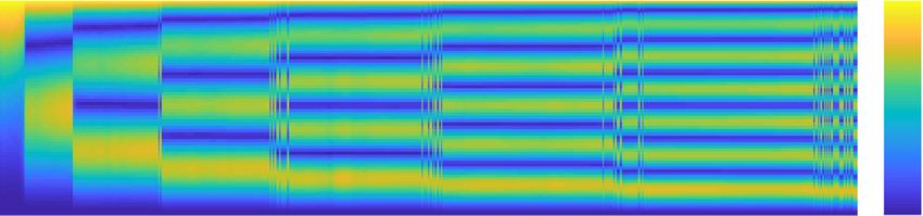
T. Leclercq, E. de Langre / Journal of Fluids and Structures 80 (2018) 77–93     81

and in the rest of this paper, the notations Y , κ , s and t always refer to the non-dimensional quantities. In terms of the
non-dimensional variables, the governing equation for the leading order static deflection in the xz-plane then reads
                                 (                     )
            1             CY                 1
      κ0′′ + κ03 +                   S02 −       C02       κ0 − CY C02 = 0                                                       (6)
            2             cd Λ               2
where the prime notation stands for curvilinear differentiation, the notations S0 = sin θ0 and C0 = cos θ0 have been used
for brevity, and with the curvature κ0 = θ0′ . The corresponding boundary conditions are θ0 = 0 at the clamped edge s = 0
and κ0 = κ0′ = 0 at the free tip s = 1. At the linear order, the equation for the non-dimensional vibration Y (s, t) is

            β u2 [
      u2 Ÿ +      2S0 Ẏ ′ + C0 (κ0 + cd Λ) Ẏ
                                                ]
            St Λ
                                           ] )′
              β u2                                β u2              β u2
          ([        (             )
                              1 2      3 2
        +             S0 + C0 + κ0 Y ′ + cd 2 C0 S0 Y ′ + Y (4) = cl 2 C02 q
                        2
                                                                                                                                 (7)
             St Λ
               2 2
                              2        2          St Λ               St
with Y = Y ′ = 0 at the clamped edge s = 0 and Y ′′ = Y ′′′ = 0 at the free tip s = 1. The lift magnification factor q(s, t) then
satisfies the Van der Pol equation

      q̈ + ε (2π C0 ) q2 − 1 q̇ + (2π C0 )2 q = AŸ .
                          (           )
                                                                                                                                 (8)

2.3. On the governing parameters

    Within the four non-dimensional parameters defined above (CY , u, Λ, β ), only three are necessary to fully characterize the
problem. In fact, for a given structure with a fixed mass and aspect ratios, the Cauchy number and the reduced velocity are
redundant parameters that are related by CY = (cd β/St2 Λ)u2 . Both quantities scale the influence of the flow to the rigidity of
the structure, but from different perspectives. The Cauchy number expresses the ratio between the leading order drag force
and the restoring structural stiffness (Tickner and Sacks, 1969; Chakrabarti, 2002; de Langre, 2008). Consequently, it controls
the level of static deflection in the xz-plane. For small CY < 1, deflection is negligible and the structure stands upright in
the flow, while for CY ≫ 1 the cylinder is highly deformed in the direction of the free-stream (Gosselin et al., 2010). On the
other hand, the reduced velocity compares the natural shedding frequency fw0 (on the straight structure) to the scale of the
natural period of the structure Ts , so it controls the dynamic behaviour of the coupled wake–structure system.
    The mass ratio β represents the amount of fluid inertia within the total inertia of the system. We do not expect the
precise value of β should significantly influence the qualitative features of the VIVs presented in this article. We also expect
the influence of the gravity and buoyancy forces on the static deflection due to the flow to remain small (Luhar and Nepf,
2011). Thus, for the sake of simplicity, we restrict this study to the case of a neutrally buoyant cylinder β = 0.5. Finally, the
aspect ratio Λ = L/D scales the relative contributions of the resistive and reactive terms. In the case of slender structures
Λ ≫ 1 as those considered in this paper, the contribution of the reactive force O(CY /Λ) to the static equilibrium shape in
Eq. (6) is in fact negligible. On the other hand, as will be shown in Section 3.3, the reactive force may be responsible for
triggering the large-amplitude flutter instability, and its influence on the vortex-induced dynamics may still be significant
near the critical threshold when the deflection is large. Thus we may not neglect a priori the terms originating from the
reactive force in Eq. (7).
    Our main interest in this study is the effect of the flow-induced bending on the properties of the vortex-induced vibrations.
In other words, we wish to compare the dynamics of structures with varying levels of deflection in the direction of the free-
stream (varying Cauchy numbers CY ), at a given reduced velocity u. However, as explained above, for a given fluid–structure
system of fixed mass and aspect ratios (β, Λ), the Cauchy number and the reduced velocity vary together as CY ∝ β u2 /Λ.
Therefore, increasing the Cauchy number with a fixed reduced velocity requires to change the structure to lower the aspect
ratio Λ. This may seem counter-intuitive, as a lower aspect ratio is classically associated with lower deflections. Indeed, the
Cauchy number is an increasing function of the aspect ratio CY ∝ Λ3 when the dimensional flow velocity, fluid density,
and Young’s modulus of the solid material are kept constant. In our case however, we allow these dimensional quantities to
vary in order to keep the reduced velocity u constant instead, and consequently the Cauchy number becomes a decreasing
function of the aspect ratio. In the limit of an infinitely slender structure Λ → +∞, the Cauchy number remains much
smaller than 1 even for arbitrarily large reduced velocities. This asymptotic case is therefore equivalent to considering a
structure that remains straight in the free-stream. For this benchmark case, the dynamic system (7)–(8) reduces to
                   β u2                          β u2
      u2 Ÿ + cd          Ẏ + Y (4) = cl                  q                                                                     (9)
                    St                            St2
      q̈ + ε (2π) q2 − 1 q̇ + (2π)2 q = AŸ
                     (           )
                                                                                                                                (10)

which is the standard system of equations for the modelling of VIVs by means of a wake oscillator, in the case of a straight
slender cylinder with flexural stiffness and hydrodynamic damping (Mukundan et al., 2009).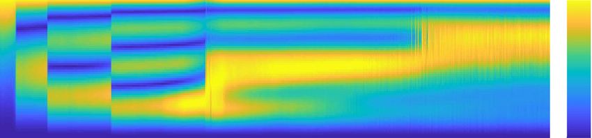
82 T. Leclercq, E. de Langre / Journal of Fluids and Structures 80 (2018) 77–93
Fig. 2. (a) Deflection in the xz-plane and (b) normal velocity profile normalized by the horizontal velocity, in the straight case (grey — ), and in deflected
cases CY = 100 (· · ·), CY = 101 (− − −), and CY = 102 (black — ) for Λ = 103 .
3. Numerical results
In order to analyse the vibration behaviour, we solve the problem defined by Eqs. (6), (7), (8) numerically. The beam is
discretized using N = 100 Gauss–Lobatto points sk = 12 (1 − cos((k − 1)/(N − 1)π )), and the curvilinear derivatives are
computed by Chebyshev collocation. For a given aspect ratio Λ, we first compute the static solution of Eq. (6) iteratively
by increasing the Cauchy number from the upright case CY = 0. After each increment, we solve Eq. (6) with a pseudo-
Newton solver (method of Broyden, 1965) using the solution at the previous step as initial guess. Then, for each value of CY
(corresponding to a given u), we solve the nonlinear system (7)–(8) using a time-stepping method, with time step dt = 10−2 .
The time derivatives are computed using implicit second order accurate finite differences. At each time step, the nonlinear
boundary value problem involving the unknown spanwise distributions (Y , q) is solved thanks to the pseudo-Newton solver.
The simulations are run for 200 periods and the last 100 periods are considered for the analysis in order to cut the transient.
3.1. Wake excitation bandwidth and inhibition of single mode lock-in
First, we discuss the influence of the deflection on the modal content of the dynamics. To do so, we compare the vibrations
of a structure that bends (finite aspect ratio Λ = 103 ) to that of a structure that remains straight (Λ → +∞), on the same
range of reduced velocities. For the structure with finite aspect ratio Λ = 103 , the variations of u within the range considered
will be associated with variations in the Cauchy number CY ∝ u2 /Λ leading to varying levels of deflections. On the other
hand, the infinitely slender cylinder will remain straight because the Cauchy number will remain asymptotically small in the
same finite range of u. We recall here that the cylinder with the finite aspect ratio is the one that deflects while the infinitely
slender one remains unbent because we compare the dynamics of the two structures on the same range of reduced velocities
(see Section 2.3 for more details).
As explained in Section 2.1, the independence principle states that the natural frequency of vortex shedding fw (s)
decreases along the span when the structure is deformed because of the projection of the free-stream on the normal direction
fw (s)/fw0 = Un0 /U = cos θ0 (s). The deforming structure is therefore subjected to a forcing by the wake on a continuum of
frequencies that broadens when the deflection is enhanced with increasing Cauchy numbers, as shown on Fig. 2.
The enrichment of the excitation spectrum significantly alters the modal content of the structural response. This is
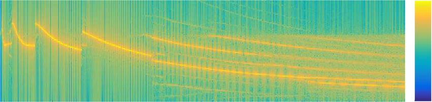
illustrated on Fig. 3 for the vibration spectrum and Fig. 4 for the spanwise localization of the vibration. In the straight case,
the structure is subject to a forcing by the wake at a single frequency along the whole span. The frequency of the vibration
remains close to the Strouhal law (f ≃ 1 on Fig. 3(a)), but slightly deviates to follow an evolution closer to that of the nearest
structural mode. As u varies, lock-in with the successive structural modes occurs in turn and frequency discontinuities mark
the transitions between consecutive lock-ins. This phenomenon is a well-known feature of the VIVs of flexible structures
perpendicular to the flow (King, 1995; Chaplin et al., 2005; Violette et al., 2010). As expected, this behaviour remains
unchanged for as long as the deflection is negligible (CY < 1 on Fig. 3(b)) in the case Λ = 103 . However, at the early
stages of reconfiguration (CY ≲ 101 on Fig. 3(b)), the ranges of reduced velocities within which lock-in with a given mode
occurs are slightly widened and increasingly shifted towards larger reduced velocities (see Table 1). For instance, lock-in
with mode 4 persists on a slightly larger range u ∈ [16.3, 29.9] when the structure is bent compared to u ∈ [15.2, 27.0]
when it is not. The modal shapes in both configurations remain on the other hand almost identical, as illustrated for u = 19.8
in Fig. 4(c), which proves that the curvature of the structure in the xz-plane only has a very limited impact on the transverse
deformation.
Following the method of Violette et al. (2010), we may interpret these results by comparing the spectrum of the nonlinear
dynamics to the frequencies of the eigenmodes found by a linear stability analysis (see Fig. 5). The details of the linear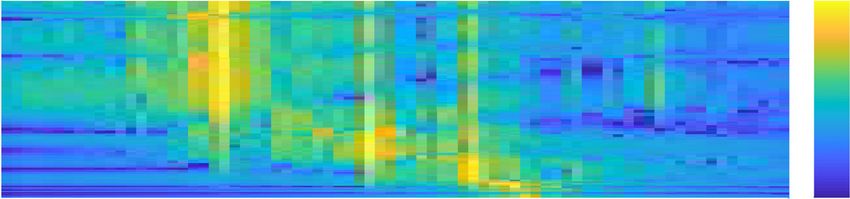
T. Leclercq, E. de Langre / Journal of Fluids and Structures 80 (2018) 77–93                            83

Table 1
Reduced velocity ranges for lock-in in the straight and bent cases (nonlinear and linear ranges).
                             Straight case (nonlinear)                      Bent case Λ = 103 (nonlinear)               Bent case Λ = 103 (linear)
  mode 1                     0–2.3                                          0–2.3                                       0–2.16
  mode 2                     2.4–6.8                                        2.4–6.9                                     2.16–6.80
  mode 3                     6.9–15.1                                       7–16.2                                      6.80–15.86
  mode 4                     15.2–27.0                                      16.3–29.9                                   15.86–28.70

stability analysis can be found in Appendix C. The eigenmodes thus found can be classified in 3 distinct types. Firstly, a
series of N unstable modes (where N is the number of discretization points sk ) with eigenvalues matching        almost exactly
the eigenvalues of the linearized wake oscillator without structural coupling ωk ≃ cos θ0 (sk )(2π 1 − (ε/2)2 − iπε ) are
                                                                                                      √
observed. They have no significant structural component (φk (s) ≃ 0), and their wake components are localized respectively
at each discretization point (|ψk (s)| ≃ δ (s − sk ) with δ the Dirac function). These modes thus correspond to the naturally
unstable free wake modes. For the sake of clarity, the continuous spectrum of the free wake oscillator itself is represented in
grey on Fig. 5(b) instead of the N individual eigenmodes spanning the area. Secondly, the modes in blue correspond closely
to the eigenmodes of the structural equation (7) without coupling with the wake. These modes may thus be designated as
the free structural modes. Finally, the four modes in black are coupled modes that each arise from lock-in with one of the
structural modes. They are all unconditionally unstable and will be referred to as the lock-in modes. Following Violette et al.
(2010), we expect lock-in with a given mode to persist in the nonlinear limit-cycle if the corresponding linear lock-in mode is
the most unstable. The comparison of the linear and nonlinear lock-in ranges in Table 1 confirms these findings and we may
thus lean on the linear analysis to interpret the dynamics observed in the limit-cycle. In particular, as deflection increases,
we notice on Fig. 5 that the broadening of the free wake spectrum allows the structural frequencies to remain within the
excitation bandwidth on a larger range of reduced velocities. Lock-in with these modes may consequently occur on these
larger ranges as well. Hence, it appears that the primary consequence of the deflection is the broadening of the free wake
spectrum due to the increased shear in the normal component of the free-stream. At leading order, a bending structure in a
uniform flow is therefore equivalent to a straight structure in a sheared flow whose profile varies, depending on the Cauchy
number, according to that of the normal flow shown on Fig. 2(b).
    When bending is more pronounced (CY > 101 ), not only one but several frequencies are involved in the spectrum of the
nonlinear limit-cycle Fig. 3(b), and the localization of the transverse vibration significantly deviates from the single-mode
shape on Fig. 4. Indeed, when the wake spectrum becomes large enough, several structural modes are excited simultaneously
at different locations along the span (several structural modes appear within the wake excitation bandwidth on Fig. 5).
Consequently, single mode lock-in is replaced by a multi-frequency response of the whole structure associated with the
spatial fragmentation of the wake into multiple cells of locally uniform frequency. As illustrated on Fig. 6, the frequency
within each wake cell matches that of the structural mode that is closest (in the frequency space) from the Strouhal law,
so that it might be said that single mode lock-in is actually replaced by multiple occurrences of lock-in along the span. It
is however noteworthy that the local wake dynamics is essentially monochromatic, while the structural dynamics involves
comparable contributions from all the excited modes at any location along the span. Besides, the linear analysis shows that,
past u > 28.7, the most unstable mode is not one of the coupled lock-in modes anymore, but is found instead within one of
the free wake modes. No fifth coupled mode that would appear because of lock-in with the fifth structural mode is observed.
It thus appears that the large shear in the normal flow hinders single mode lock-in, but leads to the simultaneous excitation
of multiple structural modes that all participate in the dynamics.
    We may finally conclude that bending primarily affects the dynamics through its influence on the component of the
free-stream normal to the cylinder. More specifically, the growing shear in the normal flow is responsible for broadening
the wake spectrum. When the deflection remains moderate, the wake excitation bandwidth remains narrow enough so
that single-mode lock-in still prevails, but on a slightly larger range of reduced frequencies. On the other hand, when the
deflection is large, several structural modes may be simultaneously excited, leading to the inhibition of single mode lock-in
replaced by a multi-frequency response to the broadband excitation. These conclusions are consistent with the observations
of Bourguet et al. (2012, 2015) for a pinned–pinned cylinder experiencing small in-line deformations, as well as those of
Vandiver (1993), Ge et al. (2011) and Srinil (2011) for straight pinned–pinned cylinders in shear flow.

3.2. Localization of the excitation and VIV mitigation

    As emphasized in the introduction, the experimental work of Assi et al. (2014) and Seyed-Aghazadeh et al. (2015) has
shown that the amplitude of the vibrations of rigid cylinders is much reduced under the effect of the curvature. The same
observation was made by Bourguet et al. (2015) regarding the VIVs of pinned–pinned flexible cylinders. Similarly, the
works of Trim et al. (2005), Ge et al. (2011) and Srinil (2011) have also shown that sheared incoming flows entailed lower
structural responses than uniform flows. Our numerical simulations indicate that this observation holds true as well for
flexible cantilever cylinders curved by the flow. Indeed, the amplitude of the VIVs of the deflecting cylinder (Λ = 103 )
reduces progressively on Fig. 7(a) compared to the straight case above the bending threshold CY > 1. For large deflections
CY > 10, the amplitude settles around approximately 1/3 of the amplitude of the straight case.
84                                        T. Leclercq, E. de Langre / Journal of Fluids and Structures 80 (2018) 77–93

Fig. 3. Comparison between the power spectral densities of the motion at the tip Y (s = 1, t) in (a) the straight case and (b) the deflected case Λ = 103 , for
varying reduced velocities u. The natural wake excitation bandwidth (WEB) is superimposed. The particular values of the reduced velocity u corresponding
to Fig. 2 are indicated as well.

Fig. 4. Comparison between the spanwise localizations of the transverse deformation in (a) the straight case and (b) the deflected case Λ = 103 , for
varying reduced velocities u. The colorplots show the temporal RMS of Y (s, t), normalized to 1 along the span. The particular values of the reduced velocity
u corresponding to Fig. 2 are indicated as well. (c) Comparison of the envelopes of the transverse deformation in the straight case (− − −) and deflected
case Λ = 103 (— ), for particular values of u corresponding to successive structural modes in the straight case.

    We may explain this reduction of amplitude by considering the energy transferred to the structure from the wake
oscillator. In non-dimensional form, the work of the oscillating lift force at a given location along the span reads e =
Ẏ · qcos2 θ0 , so that the total energy E transferred to the structure over one cycle of oscillations is the temporal mean of
e, integrated over the whole span. The evolution of E with the reduced velocity on Fig. 7(b) proves that deflection drastically
mitigates the transfer. A more detailed look at the spanwise distribution of the mean energy transfer on Fig. 8 indicates that
the excitation by the wake, which is equally distributed in the straight case, concentrates around s ∼ 0.2 as the deflection
T. Leclercq, E. de Langre / Journal of Fluids and Structures 80 (2018) 77–93                                    85

Fig. 5. Evolution of the linear frequencies of the coupled wake–structure system with the reduced velocity u, for (a) the straight case and (b) the deflected
case Λ = 103 . The unconditionally unstable free wake spectrum is represented by the grey area. The structural modes in blue are always stable. The coupled
modes, displayed in black, are always unstable. The most unstable mode for a given range of u is emphasized in bold.

Fig. 6. Spanwise distribution of power spectral density of (a) the structural motion Y and (b) the wake oscillator q, for Λ = 103 and u = 49.0. The natural
shedding frequency fw0 (s) given by the Strouhal law is superimposed in (b) (— ).

increases. This is actually quite intuitive, because the lift force varies with the square of the normal component of the free-
stream ∝ cos2 θ0 . When deflection is important, only the small region close to the clamping point remains close enough to
the vertical so as to significantly contribute to the excitation. As the Cauchy number increases and the cylinder bends more
and more, the size of that region reduces progressively. The amount of energy transferred overall is consequently reduced,
and the amplitude of the vibrations accordingly mitigated.
   Note that the discontinuities observed in the straight and low-deflection cases on Fig. 7 correspond to mode switches.
The disappearance of these jumps above u > 30 in the deflected case is consistent with the continuous evolution of the
spectrum and vibration shape reported in Figs. 3(b) and 4(b).

86                                        T. Leclercq, E. de Langre / Journal of Fluids and Structures 80 (2018) 77–93

Fig. 7. Comparison of (a) the RMS amplitude of vibration Yrms and (b) the total energy transfer E from the wake to the structure, between the straight case
(blue ◦) and the deflected case Λ = 103 (orange ▽) for varying reduced velocities u. The particular values of the reduced velocity u corresponding to Fig. 2
are indicated as well.

Fig. 8. Comparison of the spanwise distributions of energy transfer from the wake to the structure between (a) the straight case and (b) the deflected case
Λ = 103 , for varying reduced velocities u. The colorplots show the mean work of the oscillating lift force ⟨e⟩ normalized by the total energy transfer E. The
particular values of the reduced velocity u corresponding to Fig. 2 are indicated as well.

3.3. Influence of the reactive force

    Finally, we discuss the influence of the large axial component of the free-stream when the structure is highly reconfigured.
Indeed, as the flow velocity increases, the inclination of the structure switches from perpendicular to mostly parallel to the
flow. As explained in Section 2.3, the level of deflection is controlled by the Cauchy number CY ∝ u2 /Λ. We focus here on
a case where the deflection increases more rapidly with the reduced velocity than before, that is to say a structure with a
smaller aspect ratio Λ = 10.
    At first, the amplitude of vibrations on Fig. 9(a) follows the same trend as in the previous case: below CY < 1, the effect of
bending is unnoticeable, while it results in a constant amplitude much reduced compared to the straight case when bending
is significant. The amplitude is even reduced as low as 1/10th of the straight case. But conversely to the previous case, the
vibrations start growing again slowly past u ∼ 20 and they even exceed the amplitude of the straight case for u ≳ 33.5.
Above some critical threshold u ∼ 35, the amplitude finally grows continuously during the whole time of the simulation.
The VIVs are by nature a self-initiated and self-limited phenomenon. In the model, the onset of the VIVs is ensured by the
T. Leclercq, E. de Langre / Journal of Fluids and Structures 80 (2018) 77–93 87
Fig. 9. (a) Comparison of the RMS amplitude of vibration between the straight case (blue ◦) and the deflected case Λ = 10 (yellow □). (b) and (c) Linear
frequencies flin and growth rates σ of the coupled wake–structure system, for Λ = 10. The unconditionally unstable free wake spectrum is represented by
the grey area. The structural modes are in blue when stable, and in bold orange when unstable. The orange cross marks the stability threshold for structural
mode 3. The coupled mode, displayed in black, is always unstable. It is emphasized when it is the most unstable mode.
negative damping of the Van der Pol wake oscillator when the amplitude of q is small, while the limitation of the amplitude
is ensured by the nonlinear saturation of that same term. This unbounded growth is therefore not related to the VIVs, but
is instead the consequence of the onset of a flutter instability caused by the destabilizing influence of the hydrodynamic
reactive force on the large portion of the cylinder that is aligned with the free-stream (Eloy et al., 2007; Singh et al., 2012a).
This is confirmed by the results of the linear stability analysis presented on Fig. 9(b) and (c). Lock-in with structural mode
1 occurs for the smallest reduced velocities (the coupled linear mode is the most unstable as long as u < 2.30), when flow-
induced bending is still small. When deflection becomes significant (CY ≫ 1), several structural modes are simultaneously
excited by the wake on Fig. 9(b). But in this case, one of the structural modes (mode 3) is progressively destabilized as u
increases. Above u ≳ 20, the growth rate of this mode starts increasing on Fig. 9(c) until it finally becomes unstable at the
critical threshold uc = 34.9 (marked by the orange cross on Fig. 9(b) and (c)). If the effect of the curvature on the structural
modes has been proved negligible in Section 3.1, these observations prove on the other hand that the influence of the reactive
force may be very significant in the vicinity of the critical threshold. The progressive increase of the vibration amplitude from
u ∼ 20 until the actual onset of the instability uc = 34.9 is indeed concomitant with the destabilization of structural mode
3. Hence, the larger vibration amplitudes observed in this range of reduced velocities are most likely attributable to the
growing influence of the gradually destabilizing structural mode 3.
The flow-induced bending thus has competing consequences on the amplitude of the vibrations. On the one hand, we
have shown in Section 3.2 that the shrinkage of the wake excitation zone considerably mitigates the VIVs. We demonstrate88 T. Leclercq, E. de Langre / Journal of Fluids and Structures 80 (2018) 77–93
here that on the other hand, the reorientation of the structure in the direction of the free-stream may amplify the vibrations
because of the destabilizing effect of the reactive force on the structural modes. This last effect becomes significant in the
vicinity of the structural stability threshold. As explained in Appendix D, the structural stability threshold in terms of either
the reduced velocity u or the Cauchy number CY is close to proportional to the aspect ratio Λ. More slender structures may
consequently reach much higher modes and larger deflections before feeling the destabilizing influence of the reactive force.
4. Discussion and conclusion
In this paper, we have provided a qualitative analysis of the consequences of flow-induced bending on the vortex-induced
dynamics of slender flexible cylinders based on reduced order models. Overall, the effects of the deflection may impact the
features of the vibrations on two levels.
Firstly, the deformation of the cylinder changes the spanwise profile of the component of the free-stream normal to the
structure. We have shown that the increasing non-uniformity of the normal flow leads to the spreading of the wake excitation
spectrum and the localization of the energy transfer from the wake to the structure, owing to the independence principle.
These two effects result in a strong mitigation of the amplitude of the vibrations coupled with the inhibition of single mode
lock-in replaced by the simultaneous excitation of multiple structural modes. These mechanisms were indeed evidenced in
several experimental and numerical studies about the VIVs of straight cylinders in shear incoming flow, such as Vandiver
(1993), Trim et al. (2005), Srinil (2011), Ge et al. (2011) and Bourguet et al. (2013) for instance. As any deformation of a
straight cylinder in the direction of the free-stream would induce shear in the normal flow, we expect that these conclusions
are independent of the initial structural configuration, boundary conditions, or the features of the in-plane deformation. For
instance, similar observations have been reported by Bourguet et al. (2015) for a pinned–pinned cylinder initially inclined
and slightly deformed by the flow. Similarly, the smaller amplitudes of vibrations reported in Assi et al. (2014) and Seyed-
Aghazadeh et al. (2015) for rigid curved cylinders compared to straight ones is likely also the consequence of the difference in
the normal flow profiles between the two configurations. The loss of harvesting efficiency reported in Antoine et al. (2016)
when increasing the sag (and consequently the deformation) in the in-flow catenary configuration also results from the
induced shear in the normal flow.
Secondly, the deformation of the structure is responsible for a modification of the structural modes resulting from both
the flow-induced tension and the axial component of the flow through the reactive forcing term.
The effect of the tension is negligible in our case, but it should be noted that it may be of significant importance in other
situations. Indeed, the structural frequencies depend on the total stiffness of the system, which can be decomposed in the
natural bending stiffness EI specific to the structure, and an additional tension-induced stiffness. In our case, the structural
tension T = −1/2EI κ02 itself is the physical consequence of the structural stiffness EI, and so it is understandable that
the influence of the tension-induced stiffness on the natural frequencies of the structure be small compared to that of the
natural stiffness that originated it. However, in the rather common case of tensioned cables, the structural tension is either
externally controlled or flow-induced but it is in any case independent of the usually small bending stiffness. Its influence
on the structural frequencies and thus on the vortex-induced dynamics may then be totally dominant (see for instance the
study of Antoine et al., 2016), but this effect is out of the scope of the present work as the tension in this case is not related
to the flow-induced deformation of the structure.
The effect of the axial flow component may on the other hand be dramatic in the configuration chosen in this article.
When the deflection is very large, the axial flow may become the dominant component, and the added damping and stiffness
stemming from the reactive forcing on the inclined portion of the cylinder may significantly alter the structural modes.
Above some critical velocity threshold, the cylinder might undergo some large-amplitude oscillations originating from a
flutter instability. It should be noted that only the transverse stability along the y-direction has been considered in this
article, but flutter may also be initiated in the xz-plane (see Leclercq et al., 2018). However, we do not expect the in-plane
destabilization to have consequences on the vortex-induced dynamics below the stability threshold. Indeed, the geometrical
linearization performed in Appendix A.2 results in the decoupling of the small-amplitude dynamics in the two directions.
There should consequently be no interactions between the in-plane structural modes and the transverse vibrations as long
as the amplitude of vibration remains small Y /L ≪ 1. On the other hand, we have shown that the progressive destabilization
of the transverse structural modes may enhance the amplitude of the VIVs even in the stable domain. These conclusions may
not easily be generalized to other structural configurations as the stability of the structural modes is highly dependent on
the boundary conditions of the structure. The choice of the cantilever configuration in our work merely demonstrates the
potentially large consequences the axial flow may bear through the reactive force, and neglecting the terms originating from
it must only be done with great care. Nonetheless, we also found that the magnification of the vibrations due to the reactive
force becomes significant for higher modes of vibrations and larger levels of deflection as the structure is made more slender.
In this regard, it may thus be considered as a secondary effect that sets a limit to the strong abatement of the vortex-induced
vibrations more commonly observed.
We may thus conclude that the primary consequence of flow-induced deformations on the vortex-induced dynamics of
flexible cylinders is the hindrance of single mode lock-in, replaced by a multi-frequency response of the structure, and the
strong mitigation of the vibrations that rest on the modification of the spanwise profile of the normal component of the
free-stream. Neglecting the in-line deformation when assessing the features of the VIVs should therefore generally result in
an overestimation of the severity of the vibrations.T. Leclercq, E. de Langre / Journal of Fluids and Structures 80 (2018) 77–93 89
Table 2
Structural stability thresholds in terms of the flutter-specific reduced velocity v , VIV-specific reduced velocity u, and Cauchy number CY .
Critical velocity vc Critical velocity uc Critical Cauchy number CY ,c
Λ = 10 12.7 3.58 × 101 2.04 × 10³
Λ = 102 16.1 4.55 × 10² 3.30 × 10⁴
Λ = 103 17.1 4.85 × 10³ 3.74 × 10⁵
Acknowledgement
The authors would like to acknowledge financial support from the DGA/DSTL grant 2014.60.0005.
Appendix A. Derivation of the governing equations
A.1. Details about the structural model
Following Audoly and Pomeau (2010), we define a local direct orthonormal frame ei=1,2,3 = (n, w , τ ), materially attached
to the structure and such that (n, w , τ )|s=0 = (ex , ey , ez ). We also define the Darboux vector Ω = κn n + κw w + γ τ where κn
and κw are the material curvatures and γ is the twist of the cylinder. By definition, the Darboux vector is such that e′i = Ω × ei .
For an Euler–Bernoulli beam of bending stiffness EI in both (n, w)-directions, torsional stiffness GJ, and subjected to an
external force q and no external torque, the Kirchhoff equations governing the dynamics of the structure read
mr̈ = F ′ + q, 0 = M′ + τ × F (11)
with the internal force vector F = T τ + Q n + Pw and the constitutive law for the internal bending moment M =
GJ γ τ + EI κn n + EI κw w. The inextensibility condition reads r = τ , and for a cantilever beam, the boundary conditions
read r = 0 and r ′ = ez at the clamped edge s = 0, and F = M = 0 at the free end s = L. Using the second Kirchhoff law
(11) and the boundary conditions for the twist, we find that
γ = 0, Q = −EI κw′ , P = EI κn′ (12)
so that finally the curvilinear derivatives of the material frame simplify in
τ ′ = κw n − κn w , n′ = −κw τ, w ′ = κn τ (13)
and the curvilinear derivative of the internal force vector that appears on the right hand side of the first Kirchhoff equation
(11) reads
( )′
1
F′ = EI κn2 + κw2 τ + κw T − EI κw′′ n − κn T − EI κn′′ w .
( ) ( ) ( )
T+ (14)
2
The boundary conditions read r = τ = 0 at s = 0 and T = κn = κn′ = κw = κw′ = 0 at s = 1.
A.2. Linearization of the structural model
As explained in Section 2, we expand r(s, t) = r0 (s) + Y (s, t)ey where the transverse displacement Y is taken as a first
order perturbation to the static shape r0 . At the leading order the deformation is contained exclusively in the xz-plane so κn
is a first order perturbation as well and we also expand κw = κ0 + δκ and the frame vectors
τ = τ 0 + δτ, n = n0 + δn, w = ey + δw. (15)
Using (13), the inextensibility condition and all the expansions above mentioned, we obtain after some calculations the
expansions of the material frame
τ = τ 0 + Y ′ ey , n = n0 + α ey , w = ey − Y ′ τ 0 − α n0 (16)
where the small angle α and the small curvature κn satisfy
α ′ = −κ0 Y ′ , κn = κ0 α − Y ′′ (17)
and δκw = 0. Besides, expanding all the terms in (14), we obtain up to the linear order
( )′ ( )
1 3 ( )′
F′ = EI κ02 τ 0 + κ0 T − EI κ0′′ n0 + T − EI κ02 Y ′′ − EI κ02 Y ′ − EIY (4) ey .
( ) ( )
T+ (18)
2 290 T. Leclercq, E. de Langre / Journal of Fluids and Structures 80 (2018) 77–93
A.3. Linearization of the fluid forces
The oscillating lift force pw defined in (3) is a linear order term by assumption. On the other hand, the resistive and
reactive forces (1), (2) both include a leading order and a linear order term. First, the expansion of the relative velocity up
to the linear order in Y gives Urel = Ẏ ey − Uex = Ẏ ey − US0 τ 0 − UC0 n0 so that projection on the tangent direction and its
orthogonal plane using (16) yields
Uτ τ = −US0 τ 0 − US0 Y ′ ey , UN N = −UC0 n0 + Ẏ + US0 Y ′ ey .
( )
(19)
Making use of that decomposition in (1) and (2), we obtain the linearized fluid loads
( ) ( ([ ] )′ )
1 1
pam = −ma U 2
S02 − C02 κ0 n0 − ma Ÿ + 2US0 Ẏ + UC0 κ0 Y + U
′ ′ 2
S02 + C02 Y ′
ey (20)
2 2
1 1
ρ CD DU 2 |C0 |C0 n0 − ρ CD DU |C0 | Ẏ + US0 Y ′ ey .
( )
pd = (21)
2 2
A.4. Governing equations
Finally, the linearized structural acceleration reads r̈ = Ÿ ey so that substitution of (18), (20), (21) and (3) in the first
Kirchhoff equation (11) provides, after projection along τ 0 and n0 , the leading order system of equation
( )′ ( )
1 ) 1 1
EI κ02 = 0, κ0 T − EI κ0′′ + ρ CD DU 2 |C0 |C0 − ma U 2 S02 − C02 κ0 = 0
(
T+ (22)
2 2 2
with leading order boundary conditions θ0 = 0 at s = 0 and T = κ0 = κ0′ = 0 at s = L. The first equation provides the
expression of the tension T = −1/2EI κ02 . Replacing T in the second equation yields the static equilibrium equation (6) after
non-dimensionalization. Similarly, projection of (11) on ey yields
( )
3 ( )′
T − EI κ02 Y ′′ − EI κ02 Y ′ − EIY (4)
( )
mŸ =
2
( ([ ] )′ )
1
− ma Ÿ + 2US0 Ẏ ′ + UC0 κ0 Y ′ + U 2 S02 + C02 Y ′
2
1 1
− ρ CD DU |C0 | Ẏ + US0 Y + ρ ′
CL0 DU 2 C02 q
( )
(23)
2 4
which gives the VIV equation (7) after replacement of the tension and non-dimensionalization.
Appendix B. Validity of the linearization
The model used throughout this study is based on the assumption that the only relevant source of nonlinearity in the
dynamics comes from the damping term in the Van der Pol wake oscillator. This term is indeed sufficient to ensure the
saturation of the vibration amplitude in the limit-cycle to a magnitude consistent with physical observations. However,
the linearization leading to the governing equation for the structure (7) relies on the assumption that the transverse
displacement Y is a small perturbation to the leading order deformation r0 (s), while the amplitude of the limit-cycle
oscillations due to VIVs is not infinitesimal. Thus, the adequacy of the linearization detailed in Appendix A for modelling
VIVs requires verification.
The linearization of the structural model performed in Appendix A.2 is purely geometrical and holds as long as Y ≪ L.
The numerical results displayed on Figs. 7(a) and 9(a) indicate that the amplitude of the transverse perturbation does not
exceed Y ≲ 0.5D in the case of VIVs. The geometrical linearization thus still holds in the limit-cycle for the slender structures
considered in this work Λ = L/D ≫ 1.
On the other hand, the linearization of the fluid forces performed in Appendix A.3 relies on the additional assumption
that the transverse velocity is small compared to the free-stream Ẏ ≪ U. The frequency of the VIVs is approximately equal to
fw0 = St U /D as shown on Fig. 3. Assuming an amplitude Y ∼ 0.5D and with St = 0.2, the order of magnitude of the transverse
velocity scales as Ẏ ∼ 2π fw0 Y ∼ 0.6U, which is at the mathematical limit of validity of the linearization. Nonetheless,
considering only the linear contribution of the fluid forces in the dynamic equation is consistent with the leading-order
nature of the models generally used in VIV studies involving wake oscillator models (Skop and Luo, 2001; Facchinetti et
al., 2004b; Mathelin and de Langre, 2005; Mukundan et al., 2009). A more detailed discussion about the appropriateness
of such an approximation can be found in Skop and Balasubramanian (1997). If the nonlinearity in the Van der Pol wake
oscillator is critical in the limitation of the amplitude of the vibrations in the limit-cycle, we expect that the influence of
other nonlinearities should be less significant on a qualitative point of view. More details about the influence of nonlinearities
arising from the structure, the fluid forces, or the coupling between them can be found in Srinil and Zanganeh (2012).
Finally, when the system becomes unstable to flutter, the amplitude of the oscillations becomes too large for the
geometrical linearization of Appendix A.2 to remain valid. In this case, nonlinear coupling between the transverse and in-
plane directions in the structural equation would eventually lead to a complex large-amplitude 3D motion.You can also read