The Allen Cell Structure Segmenter: a new open source toolkit for segmenting 3D intracellular structures in fluorescence microscopy images - bioRxiv
←
→
Page content transcription
If your browser does not render page correctly, please read the page content below
bioRxiv preprint first posted online Dec. 8, 2018; doi: http://dx.doi.org/10.1101/491035. The copyright holder for this preprint (which
       was not peer-reviewed) is the author/funder, who has granted bioRxiv a license to display the preprint in perpetuity.
                                   It is made available under a CC-BY-NC 4.0 International license.

      The Allen Cell Structure Segmenter: a new open source
      toolkit for segmenting 3D intracellular structures in
      fluorescence microscopy images

      Jianxu Chen, Liya Ding, Matheus P. Viana, Melissa C. Hendershott, Ruian Yang,
      Irina A. Mueller, and Susanne M. Rafelski

      Abstract
      A continuing challenge in quantitative cell biology is the accurate and robust 3D segmentation of
      structures of interest from fluorescence microscopy images in an automated, reproducible, and widely
      accessible manner for subsequent interpretable data analysis. We describe the Allen Cell Structure
      Segmenter, a new Python-based open source toolkit developed for 3D segmentation of intracellular
      structures in fluorescence microscope images. This toolkit brings together classic image segmentation and
      iterative deep learning workflows first to generate initial high-quality 3D intracellular structure
      segmentations and then to easily curate these results to generate the ground truths for building robust and
      accurate deep learning models. The toolkit takes advantage of the high-replicate 3D live cell image data
      collected at the Allen Institute for Cell Science of over 30 endogenous fluorescently tagged human
      induced pluripotent stem cell (hiPSC) lines. Each cell line represents a different intracellular structure
      with one or more distinct localization patterns within undifferentiated hiPS cells and hiPSC-derived
      cardiomyocytes. The Allen Cell Structure Segmenter consists of two complementary elements, a classic
      image segmentation workflow with a restricted set of algorithms and parameters and an iterative deep
      learning segmentation workflow. We created a collection of 20 classic image segmentation workflows
      based on 20 distinct and representative intracellular structure localization patterns as a “lookup table”
      reference and starting point for users. The iterative deep learning workflow can take over when the classic
      segmentation workflow is insufficient. Two straightforward “human-in-the-loop” curation strategies
      convert a set of classic image segmentation workflow results into a set of 3D ground truth images for
      iterative model training without the need for manual painting in 3D. The deep learning model
      architectures used in this toolkit were designed and tested specifically for 3D fluorescence microscope
      images and implemented as readable scripts. This toolkit was applied to the robust segmentation of
      fluorescent lamin B1, which exhibits significant variability in its localization pattern during the cell cycle.
      The Allen Cell Structure Segmenter thus leverages state of the art computer vision algorithms in an
      accessible way to facilitate their application by the experimental biology researcher.
bioRxiv preprint first posted online Dec. 8, 2018; doi: http://dx.doi.org/10.1101/491035. The copyright holder for this preprint (which
was not peer-reviewed) is the author/funder, who has granted bioRxiv a license to display the preprint in perpetuity.
It is made available under a CC-BY-NC 4.0 International license.
Introduction
Modern fluorescence microscopy has revolutionized imaging of tissues, cells, subcellular structures, and
proteins [Kervrann et al., 2016]. The resulting multi-dimensional image data (3D, time-lapse, multiple
imaging channels, or combinations thereof, etc.) require further analysis with a variety of qualitative and
quantitative approaches. Simple visual inspection of small image data sets is used to rapidly assess
general image quality or compare differences among experimental conditions. Quantitative and automated
analysis approaches, however, become necessary when the number of images is large, the differences
between experimental conditions are subtle or complex, or the image data and their interpretations are
used to develop data-driven analyses and models. Quantifying images becomes especially important when
dealing with 3D image data where even a straightforward comparison between two conditions can be
difficult without quantitative measurements. Segmentation, the identification of every pixel (or voxel) that
is either part or not part of that object, is key to extracting interpretable, quantitative measurements of an
object in an image, permitting measurement of size, shape, number of objects and intensity of a given
object, for example.
The large number of different sizes and shapes of structures found in cells makes image segmentation
particularly challenging. Furthermore, 3D image data are inherently harder to work with than 2D images,
presenting an additional challenge for cellular image segmentation and analysis. Existing 3D image
segmentation methods can be categorized as classic image processing algorithms, traditional machine
learning, and deep learning methods. Classic image processing algorithms are the most widely used by
the cell biological research community and are accessible in two main ways. Some algorithms are
available as collections of basic functions in several open platforms, including the widely-used ImageJ
[Schindelin et al., 2012], CellProfiler [Carpenter et al., 2006, McQuin et al., 2018], Icy [De Chaumont et
al., 2012], and ITK-SNAP [Yushkevich et al., 2006]. However, basic functions in the open platforms are
often not sufficiently accurate or up to date [Jerman et al., 2016]. Other published algorithms may be
designed for a specific structure in a specific imaging modality and are often implemented and released
individually [Neila et al., 2016, Hodneland et al., 2013, Smith and Barton, 2014]. Compared to general
image processing platforms, such tools are less broadly applicable and often less convenient to apply.
Machine learning algorithms can also facilitate segmentation of 2D and 3D fluorescence microscopy
images. Traditional machine learning algorithms, e.g., random forest and supporting vector machine, have
been integrated successfully into openly accessible tools such as trainable WEKA segmentation
[Arganda-Carreras et al., 2017] in ImageJ and ilastik [Sommer et al., 2011]. Users simply manually paint
on selective pixels/voxels as foreground and background samples to create a ground truth training set. A
traditional machine learning model is then automatically trained and applied on all selected images. While
easy to use, these traditional machine learning models and tools are less effective than deep learning
models especially when segmenting objects with occluded boundaries (e.g. tightly packed or highly
textured objects [Çiçek et al., 2016, Chen et al., 2016B, Chen et al., 2017]. Unfortunately, deep learning
models are “training data hungry.” Thus tedious manual painting in 3D quickly becomes prohibitive for
generating sufficient 3D ground truth data. Additionally, even if an adequate 3D ground truth can be
prepared, access to convenient tools for building/deploying these deep learning models is currently
prohibitive for many biologists. Existing tools, such as NiftyNet [Gibson et al., 2018] or DLTK
[Pawlowski et al., 2017], are difficult to use without sufficient experience in deep learning and computer
vision. Other tools, e.g., Aivia Cloud [DRVISION, 2018], are easier to use but not openly accessible.
The Allen Institute for Cell Science has developed a pipeline that generates high-replicate, dynamic
image data on cell organization and activities using a collection of endogenous fluorescently tagged
human induced pluripotent stem cell (hiPSC) lines (Allen Cell Collection; allencell.org; [Roberts et al.,bioRxiv preprint first posted online Dec. 8, 2018; doi: http://dx.doi.org/10.1101/491035. The copyright holder for this preprint (which
was not peer-reviewed) is the author/funder, who has granted bioRxiv a license to display the preprint in perpetuity.
It is made available under a CC-BY-NC 4.0 International license.
2017]). Most lines express a monoallelic mEGFP-tagged protein that represents a particular intracellular
structure (exceptions are the tagged sialyltransferase 1 line and the Ras-related protein Rab5-a line, which
are also available as biallelic lines and the centrin-2 line, which is tagged with mTagRFP-T). To enable
quantitative image and data analyses, we generated accurate and robust segmentations for over 30
intracellular 3D structure localization patterns. By developing and testing a diverse set of traditional
segmentation algorithms on a wide range of intracellular structures, we identified a conceptually simple
“classic image processing workflow” involving a limited number of classic image processing steps and
algorithms that generated high-quality segmentations of these structures. These segmentations permitted
initial analyses of basic morphometric features of these structures including size, number, shape, and
location within the cell, and form the basis for more complicated feature parameterizations (Fig. 1A). To
enhance the accuracy and robustness of these segmentations, we also developed a novel “iterative deep
learning workflow” (Fig. 1B) that takes advantage of these high-quality classic segmentation results and
applies them as an initial ground truth in an iterative deep learning-based approach to image
segmentation.
These workflows are packaged into the Allen Cell Structure Segmenter, an open-source, Python-based
toolkit for segmentation of 3D microscope images. We developed this toolkit to make both workflows
accessible to cell biologists wishing to quantify and analyze their own image data. The Segmenter offers
two key advantages over other image processing packages. First, the classic image segmentation
workflow streamlines algorithm and parameter choice. Users are provided with a “lookup table” of classic
image segmentation workflows for 20 intracellular structure localization patterns with varying
morphological properties that can be used as a starting point for segmentation. Second, the iterative deep
learning workflow provides users with tools to apply results from the classic segmentation workflow to
generate ground truth segmentations for training deep learning models, without manual painting, and then
to use these models to iteratively improve those segmentation results.bioRxiv preprint first posted online Dec. 8, 2018; doi: http://dx.doi.org/10.1101/491035. The copyright holder for this preprint (which
was not peer-reviewed) is the author/funder, who has granted bioRxiv a license to display the preprint in perpetuity.
It is made available under a CC-BY-NC 4.0 International license.
Results and Discussion
General overview of the Allen Cell Structure Segmenter
The goal of the Allen Cell Structure Segmenter is to make flexible, robust, state-of-the-art 3D
segmentation methods accessible to cell biology researchers. While developed specifically for the 3D
segmentation of intracellular structures, the Segmenter may also be applicable to a variety of other image
segmentation applications. It seamlessly integrates a traditional image segmentation workflow and an
iterative deep learning workflow to streamline the segmentation process (Fig.1). The classic image
segmentation workflow is based on a restricted set of both standard and cutting-edge algorithms and
tunable parameters (Fig.1A) that we identified to be optimal for segmenting over 30 different intracellular
structure localization patterns. We created a suite of 20 intracellular structure segmentation workflows
which we present in a lookup table as a starting point for users to solve their own segmentation tasks (Fig.
2). In the iterative deep learning workflow of the Segmenter, we describe two new strategies for preparing
3D ground truth images without laborious and subjective manual painting in 3D (Fig. 1B). The training
and testing of the deep learning model are customized for intracellular structures in 3D fluorescence
microscopy images and implemented as readable scripts for researchers without experience in deep
learning.
The classic image segmentation and iterative deep learning workflows complement each other – the
classic image segmentation workflow can generate sufficiently accurate segmentations for a wide range
of intracellular structures for analysis purposes. However, when the accuracy or robustness of the optimal
classic image segmentation workflow is insufficient, the iterative deep learning workflow can boost
segmentation performance. Conversely, the classic segmentation workflow facilitates the application of
deep learning models to 3D segmentation by generating candidate segmentations for an initial ground
truth for model training. We have thus developed a new toolkit for 3D fluorescence microscopy image
segmentation that (1) is applicable to a wide range of structures, (2) achieves state-of-the-art accuracy and
robustness, and (3) is easy to use for cell biology researchers.
The classic image segmentation workflow
The challenge of designing classic image segmentation algorithms for a large number of distinct
intracellular structures led us to a simple 3-step workflow. The steps include a restricted set of image
processing algorithm choices and tunable parameters to effectively segment a wide range of structure
localization patterns. The classic image segmentation workflow begins with a two-part pre-processing
step, intensity normalization and smoothing, followed by the core segmentation algorithms, and ends with
a post-processing step. Pre-processing prepares the original 3D microscope images for the core
segmentation algorithms. Intensity normalization helps the segmentation be more robust to different
imaging inconsistencies, including microscopy artifacts, debris from dead cells, etc., such that the same
structures in different sets of images have similar intensity values above background when fed into the
core segmentation algorithms (Fig. 3A). Smoothing reduces background noise from the microscope and
other sources to improve segmentation algorithm performance. The choice of smoothing algorithm
depends on the morphology of the intracellular structure (Fig. 3B). The core of the classic image
segmentation workflow is a collection of algorithms for segmenting objects with different morphological
characteristics (Fig. 4). This step takes in the pre-processed 3D image stack and generates a preliminary
binary segmentation as input into the post-processing step. The final, post-processing step then fine-tunes
the preliminary binary segmentations such as by filling holes or filtering by object size, turning them intobioRxiv preprint first posted online Dec. 8, 2018; doi: http://dx.doi.org/10.1101/491035. The copyright holder for this preprint (which
was not peer-reviewed) is the author/funder, who has granted bioRxiv a license to display the preprint in perpetuity.
It is made available under a CC-BY-NC 4.0 International license.
a final result (Fig. 5). The classic image segmentation workflow for a specific structure localization
pattern may consist of just one of the core algorithms or it may require a combination of several core
algorithms (Fig. 2).
Application of the classic image segmentation workflow to segmentation of over 30 intracellular
structure localization patterns
We applied the classic image segmentation workflow to 3D images of over 30 fluorescently tagged
proteins, each representing different intracellular structures. Structures were imaged in two different cell
types, the undifferentiated hiPS cell and the hiPSC-derived cardiomyocyte. The tagged proteins
representing these structures exhibited different expression levels and localization patterns in these two
cell types. Certain structures also varied in their localization patterns in a cell cycle-dependent manner.
Together, this led to over 30 distinct intracellular structure localization patterns, which we used to
develop and test the classic image segmentation workflow. A key decision point for any segmentation
task is the targeted level of accuracy. This is a function of several factors including: the size of the
structure, the limits of resolution and detection for that structure, the goal of the subsequent analysis, and
the effort required to obtain any given target accuracy. In general, we aimed to be consistent with
observations in the literature about the structure and to obtain segmentations useful for 3D visualization.
For example, our alpha tubulin segmentation workflow (Fig. 2) describes where the microtubules
primarily localize and is detailed enough to generate a reasonable 3D visualization, but does not take
known structural properties, such as the persistence length of microtubules, into account [Gan et al.,
2016]. We also addressed the blurring of the boundaries of the structure arising from the resolution limits
of fluorescence microscopy. Depending on both the contrast setting of the image and the parameters of a
given segmentation algorithm, the resultant binary image can vary significantly. For example,
segmentation of a mitochondrial tubule can result in segmented tubules of varying width (Fig. 6). To
establish a consistent baseline of how to detect the blurred boundary, we used a fluorescently tagged
mitochondrial matrix marker as a test structure and picked the segmentation parameter that most closely
matches EM-based measurements of mitochondria in human stem cells ([Bukowiecki et al. 2014, Niclis et
al. 2015]; see methods). We then used the resultant combination of contrast settings and object boundary
setting as a consistent target for the creation of the other intracellular structure segmentation workflows.
Application of the classic segmentation workflow with these structure target criteria culminated in the
intracellular structure look-up table of segmentation workflows for 20 selected distinct structure
localization patterns (Fig. 2). These classic image segmentation workflows significantly improved
segmentations compared with a set of 22 common baseline algorithms, including both global and local
thresholding (Fig. 7). We found that for structures with similar morphological properties, the same series
of algorithm choices resulted in successful segmentation (compare workflow diagrams in rows 5 and 6 in
Fig. 2). However, the parameter values for the best result still varied. The structure segmentation look-up
table and accompanying 3D z-stack movies (Fig. 2 and allencell.org/segmenter) thus serve as a guide for
which segmentation workflow (set of algorithm steps and parameter values) is a good starting point for a
user’s particular segmentation task. The classic image segmentation workflow component of the Allen
Cell Structure Segmenter is openly accessible at allencell.org/segmenter. For each example in the lookup
table, the specific workflow and accompanying algorithm parameters, fine-tuned on our data, are preset in
a workflow-specific Jupyter notebook and accompanying “pseudocode” (see Supplemental Information)
for rapid referencing and initial testing. If the preset parameters don’t generate satisfactory segmentation
results on user data, the parameters can be adjusted and assessed directly within the Jupyter notebook via
an embedded 3D viewer. Step by step suggestions of which parameters to adjust are also included to help
the user.bioRxiv preprint first posted online Dec. 8, 2018; doi: http://dx.doi.org/10.1101/491035. The copyright holder for this preprint (which
was not peer-reviewed) is the author/funder, who has granted bioRxiv a license to display the preprint in perpetuity.
It is made available under a CC-BY-NC 4.0 International license.
The iterative deep learning workflow
The aim of the iterative deep learning workflow (Fig. 1B) is to improve segmentation accuracy and
robustness for situations where the classic image segmentation workflow is insufficient. It applies the
concept of incremental learning [Schlimmer et al., 1986] to iteratively improve segmentation results. The
segmentation results from the classic image segmentation workflow provide us with a set of 3D
segmentation images that have the potential to be used as a ground truth for deep learning purposes.
However, the accuracy of these results is often not uniform for all images. Instead, the greatest accuracy
is generated in subsets of images or specific regions within images. We developed and tested two human-
in-the-loop strategies, sorting and merging, to convert a set of classic image segmentation workflow
results into an acceptable 3D ground truth image set for model training. These straightforward human-in-
the-loop strategies do not involve any manual painting of the 3D structure, but still incorporate human
knowledge into curating high-quality segmentation ground truth images. These first curated results from
the classic image segmentation workflow can then be used as a starting point to train the first model. The
segmentation results of the first model can once again be curated to provide a second, improved ground
truth data set to create a second, improved segmentation model and so on for any number of iterations.
Iterations can also be performed by combining segmentation results from several deep learning models
via the merging and sorting strategies to further improve the resultant model. This approach thus
eliminates the need for a large set of training data. The iterative deep learning workflow is implemented
in an easily accessible way and with minimal tunable parameters. Specifically, users put raw images and
training ground truths (segmentation images) in the same folder following a prescribed naming
convention and set a few parameters that vary depending on image resolution and imaging modality. The
details of building models, setting hyper-parameters, training the models, and so on, are handled
automatically in a way that is designed and optimized for 3D fluorescence microscopy images.
Application of the iterative deep learning workflow generates a more accurate and robust lamin B1
segmentation
Image-to-image variation and cell-to-cell variation are two common scenarios in which the classic image
segmentation workflow may not be sufficiently robust to data variation. For example, algorithms in the
classic segmentation workflow do not always handle the image-to-image variation that arises within a
dataset due to differences in biological and/or microscopy imaging conditions. In this case, a simple
approach to preparing a ground truth segmentation image set is to sort segmented 3D images into
“accept” or “reject” categories and only use the accepted images for initial model training (Fig. 8). The
subsequent deep learning model may end up more robust to image-to-image variation because it
incorporates contextual knowledge, which the classic segmentation workflow algorithms are incapable of
doing. Similarly, within the same image, cells at different stages of the cell cycle may exhibit distinct
structure morphologies or fluorescence intensities since interphase and mitotic structures can differ
dramatically. In this case, two (or more) different segmentation parameters or algorithms might permit
both types of structure localization patterns to be well-segmented, but two sets of parameters or
algorithms cannot normally be applied to the same image. With the aid of a simple image editing tool,
such as those available through ImageJ or ITK-SNAP, however, specific regions of interest within an
image can be manually circled and masked. Different parameter sets or algorithms are then applied to
each of these regions, and the results merged into one single segmentation ground truth for that imagebioRxiv preprint first posted online Dec. 8, 2018; doi: http://dx.doi.org/10.1101/491035. The copyright holder for this preprint (which
was not peer-reviewed) is the author/funder, who has granted bioRxiv a license to display the preprint in perpetuity.
It is made available under a CC-BY-NC 4.0 International license.
(Fig. 9). A single deep learning model usually has sufficient representation capacity to learn all such
variations within the image.
To demonstrate the segmentation accuracy and robustness achievable by the iterative deep learning
workflow, we applied this workflow to the segmentation of lamin B1 images (Fig. 10). The lamin B1
localization pattern changes dramatically through the cell cycle, changing from a thin shell around the
nucleus in interphase to a variable, wavy pattern during mitosis. This significant difference in localization
patterns created a challenge for a classic image segmentation approach. To address this, we first built a
classic image segmentation workflow to segment lamin B1 in interphase cells (Fig. 2). The best core
algorithm to obtain accurate segmentation of this lamin B1 shell depended on generating an automatic
seed in the center of each nucleus for the subsequent watershed algorithm. This automatic seeding was
performed on the center slice of the 3D image stack, where most of the nuclei were easily detectable.
However, this automatic seeding step sometimes failed, especially for cells with nuclei positioned above
or below this center slice (blue arrows in Fig. 10). Further, as expected, mitotic cells in the image were
not successfully segmented with this lamin B1 interphase-specific segmentation workflow (yellow arrows
Fig. 10). From an initial set of 80 segmented images, only eight fell into the “keep” sorting category. The
rest of the images either failed in the automatic seeding step or contained mitotic cells, which could
therefore not be used as a ground truth. However, a first iteration deep learning model based only on these
eight image stacks as its initial ground truth generated lamin B1 segmentations that picked up all
interphase nuclei in all 80 images. This was an improvement from 85% to 100% when considering
individual interphase nuclei and an improvement from 20% to 100% when considering entire image fields
(e.g. an image field can fail if a single nucleus is not detected). In the second iteration of this workflow,
we manually circled mitotic cells in 22 additional images and applied a separate classic image
segmentation workflow for mitotis-specific lamin B1 localization patterns (Fig. 2). We then merged the
interphase lamin B1 segmentation results from the first deep learning model with the mitotic lamin B1
segmentations obtained from the classic workflow to build a new training set out of these 22 images. This
second iteration of a lamin B1 segmentation deep learning model generated successful lamin B1
segmentations for all interphase and mitotic cells in the original 80 images.
The Allen Cell Structure Segmenter is a powerful toolkit for the 3D segmentation of intracellular
structures in fluorescence microscope images. The Segmenter combines a streamlined collection of
selected standard and cutting-edge classic image segmentation algorithms with a suite of preset classic
image segmentation workflows for 20 distinct intracellular structure patterns and with a novel iterative
deep learning segmentation workflow. The classic image segmentation workflow together with the
lookup table should provide users with a straightforward starting point for their own basic segmentation
needs. More challenging segmentation tasks can benefit from the complementary approach of the classic
and the iterative deep learning segmentation workflows. This combined approach permits training of deep
learning models that can successfully segment different structure localization patterns within a single
image. Two of the most significant challenges to creating robust useful segmentation methods for 3D
quantitative analysis of cell behavior is to detect all instances of the cell or structure within the entire
image and to do so successfully over time, especially if the cell or structure changes [Ulman et al., 2017].
This is required, for example, to capture the dynamic behavior of neighboring cells or neighboring
structures within cells. The challenge here is that any cell or structure missed within one image or within
one timepoint of a timeseries significantly reduces the analyzable data set. The success of our joint classic
and iterative deep learning approach in improving the detection of all nuclei in an image from 20 to 100%
with just one iteration of the model suggests great potential of applying this approach to the robust,
automated segmentation of entire images of cells and intracellular structures in time.bioRxiv preprint first posted online Dec. 8, 2018; doi: http://dx.doi.org/10.1101/491035. The copyright holder for this preprint (which
was not peer-reviewed) is the author/funder, who has granted bioRxiv a license to display the preprint in perpetuity.
It is made available under a CC-BY-NC 4.0 International license.
Materials and Methods
Data collection for toolkit development
The image segmentation toolkit has been applied to data produced at the Allen Institute for Cell Science
using gene-edited, human induced pluripotent stem cells (hiPSCs) in both the undifferentiated stem cell
and hiPSC-derived cardiomyocytes. Briefly, CRISPR/Cas9 was used to introduce mEGFP and mTagRFP-
T tags to proteins localizing to known intracellular structures [Roberts et al., 2017, Haupt et al., 2018].
Clonal, FP-tagged lines were generated for each intracellular structure of interest and were used in
imaging experiments in which undifferentiated hiPS cells were labeled with membrane dye (CellMask
Deep Red) and DNA dye (NucBlue Live) to mark cell boundaries and the nucleus (see the SOP at
allencell.org). Edited hiPSC cell lines were differentiated into cardiomyocytes using a small-molecule
protocol, as described previously (allencell.org and [Roberts et al., 2018]). For imaging, cells were plated
onto glass bottom plates coated with matrigel for undifferentiated hiPS cells and polyethyleneimine and
laminin for cardiomyocytes (see SOPs at allencell.org), respectively and were imaged using a ZEISS
spinning-disk microscope with a 100x/1.25 Objective C-Apochromat W Corr M27, a CSU-X1 Yokogawa
spinning-disk head or a 40x/1.2 NA W C-Apochromat Korr UV Vis IR objective, and Hamamatsu Orca
Flash 4.0 camera. Imaging settings were optimized for Nyquist sampling. Voxel sizes were 0.108 µm ×
0.108 µm × 0.290 µm in x, y, and z, respectively, for 100x, hiPSC images and 0.128 µm × 0.128 µm ×
0.290 µm in x, y, and z, respectively, for 40x, cardiomyocyte images. The mEGFP-tagged Tom20 line
was transfected with mCherry-Mito-7 construct (Michael Davidson, addgene #55102) using 6 μl per well
of transfection mixture containing 25 μl Opti-MEM (ThermoFisher #31985-070), 1.5 μl GeneJuice
(Millipore #70967) and 1 ug endotoxin free plasmid. Transfected cells were imaged the next day on a
ZEISS spinning disk confocal microscope as above. All channels were acquired at each z-step.
Algorithms in the classic image segmentation workflow
Step 1: Pre-processing. To prepare images for segmentation, we first performed intensity normalization
and smoothing. Our toolkit includes two normalization algorithms to choose from, min-max (MM) and
auto-contrast normalization (AC). Min-max normalization transforms the full range of intensity values
within the stack into the range [0,1]. Auto-contrast normalization adjusts the image contrast by
suppressing extremely low/high intensities. To do this, the mean and standard deviation (std) of intensity
is first estimated by fitting a Gaussian distribution to the whole stack intensity profile. Then, the full
intensity range is cut off to the range [mean - a × std, mean + b × std], and then normalized to the range
[0, 1] (Fig. 3A). The parameters, a and b, can be computed automatically based on a subset of typical
images or can be user-defined. Auto-contrast is recommended by default. Min-max normalization should
be used when the voxels with highest intensities are the target in the structure and should not be
suppressed. For example, in “point-source” structures, such as centrin-2 (centrioles), the voxels with
highest intensities usually reside in the center of the structure, making them critical to preserve. In
addition to intensity normalization, there are three smoothing operations available in the pre-processing
step: 3D Gaussian smoothing (G3), slice-by-slice 2D Gaussian smoothing (G2), and edge-preserving
smoothing (ES; [Perona and Malik, 1990]). 3D Gaussian smoothing generally works well. However, if
the target structure consists of dense filaments, an edge-preserving smoothing operation may be more
effective (Fig. 3B). Slice-by-slice 2D Gaussian smoothing should be used when the movement of the
intracellular structure is faster than the time interval between consecutive z-slices during live 3D imaging.
In this situation, 3D smoothing may further aggravate the subtle shift of the structure in consecutive z-
slices.bioRxiv preprint first posted online Dec. 8, 2018; doi: http://dx.doi.org/10.1101/491035. The copyright holder for this preprint (which
was not peer-reviewed) is the author/funder, who has granted bioRxiv a license to display the preprint in perpetuity.
It is made available under a CC-BY-NC 4.0 International license.
Step 2: Core segmentation algorithms. After pre-processing the images, they are segmented via a
selection of core segmentation algorithms (Fig. 1A). 2D and 3D filament filters (F2 and F3; Fig. 4A;
[Jerman et al., 2016]) are suitable for structures with curvi-linear shape in each 2D frame (e.g. Sec61 beta
in Fig. 4A) or filamentous shape in 3D (e.g. alpha tubulin in Fig. 4A). The 2D and 3D spot filters (S2 and
S3) compute the Laplacian of the Gaussian of the image in either 2D or 3D and thus can detect similar yet
distinct spot-like localization patterns (Fig. 4B). The “point-source” desmoplakin localization pattern,
exhibits as a round and fluorescence-filled shape in 3D. The S3 filter is more accurate for desmoplakin
than the S2 filter, which stretches filled, round objects in the z-direction. For structures with a more
general spotted appearance within each 2D frame instead of separate round structures (e.g. fibrillarin vs.
desmoplakin in Fig. 4B), the S3 filter may fail to detect obvious structures while the S2 filter performs
much better. The core watershed algorithm (W) can be used in two different ways. First, watershed can be
applied to distance transformations of S3 filter results using local maxima as seeds to further separate
proximal structures (Fig. 4C). Second, watershed can also be directly applied to the pre-processed image
with seeds (detected by another algorithm) to segment structures enclosed in fluorescent shells (e.g. lamin
B1 in Fig. 4D). The last core segmentation algorithm, masked object thresholding (MO) is designed for
intracellular structure patterns with varying granularity or intensity (e.g. nucleophosmin in Fig. 4E). The
MO threshold algorithm first applies an automated global threshold to generate a pre-segmentation result,
which is used as a mask to permit an Otsu threshold to be applied within each pre-segmentation object.
For example, the nucleophosmin localization pattern includes a primary localization to the granular
component of the nucleolus and a weaker, secondary localization to other parts of both the nucleolus and
nucleus. Therefore, we first apply a relatively low global threshold to roughly segment each nucleus We
next compute a local threshold within individual nuclei to segment the nucleophosmin pattern (Fig. 4E).
Compared to traditional global thresholding, masked-object thresholding performs more robustly to
variations in intensity of the nucleophosmin localization pattern in different nuclei within the same image.
Step 3: Post-processing. Three different algorithms are available for the final post-processing step in the
workflow (Fig. 5). These algorithms refine the binary core segmentation algorithm result to return a final
segmentation. Not all post-processing algorithms are needed for every structure. The first algorithm is a
morphological hole-filling algorithm (HF) that can resolve incorrect holes that may have appeared in
certain segmented objects to represent the target structure more accurately (Fig. 5A). Second, a
straightforward size filter (S) can be used to remove unreasonably small or large objects from the core
segmentation algorithm result. (Fig. 5A). Finally, a specialized topology-preserving thinning operation
(TT) can be applied to refine the preliminary segmentation without changing the topology (e.g., breaking
any continuous but thin structures). This thinning is accomplished by first skeletonizing the preliminary
segmentation, then eroding the segmentation in 3D on all voxels that are not themselves within a certain
distance from the skeleton (Fig. 5B).
Deep Learning Models and Training
The deep learning models employed in our iterative deep leaning workflow are two fully convolutional
networks specially customized for 3D fluorescence microscopy images: Net_basic and Net_zoom (Fig.
11; [Long et al., 2015] for more details about fully convolutional networks). Net_basic is a variant of a
3D U-Net [Çiçek et al., 2016] with (1) max pooling in all xyz dimensions replaced by max pooling in xy
only, (2) zeros padding removed from all 3D convolution and (3) auxiliary loss added for deep
supervision [Chen et al., 2016A]. Net_zoom has a similar architecture to Net_basic, but with an extrabioRxiv preprint first posted online Dec. 8, 2018; doi: http://dx.doi.org/10.1101/491035. The copyright holder for this preprint (which
was not peer-reviewed) is the author/funder, who has granted bioRxiv a license to display the preprint in perpetuity.
It is made available under a CC-BY-NC 4.0 International license.
pooling layer with variable ratio to further enlarge the effective receptive field. Such modifications are
made to deal with anisotropic dimensions common in 3D microscopy images and to improve the
performance in segmenting tenuous structures, such as the thin nuclear envelope.
In each training iteration, random data augmentation is applied on each image and a batch of sample
patches are randomly cropped from the augmented images. In practice, the patch size (i.e., the size of
model input) and batch size (i.e., the number of samples trained simultaneously in each iteration) depend
on the available GPU memory. For example, a single Nvidia GeForce GPU with 12GB memory is used in
our experiments. With this setup, we choose a batch size of 4 and each input sample patch has size 140 ×
140 × 44 voxels for Net_basic and 420 × 420 × 72 voxels for Net_zoom. For data augmentation, we adopt
a random rotation by θ (a random value from 0 to π) and a random horizontal flip with probability 0.5.
Weighted cross-entropy is used in all the loss functions, where a per-voxel weight is taken as a separate
input image (e.g., cost map). By default, we use a weight = 1 for all voxels, but one can assign a larger
weight on those extremely critical regions or assign zeros to those regions that do not count for the loss
function. Models are trained with Adam [Kingma and Ba, 2014] with constant learning rate 0.00001 and
L2 regularization with weight 0.005.
Segmentation algorithm comparisons
Representative sample images from 20 structure localization patterns were used to compare segmentation
results between the Allen Cell Structure Segmenter classic image segmentation workflow, 14 global and 8
local thresholding algorithms (Fig. 7). All images corresponded to the maximum intensity projection of a
z-slice of choice plus and minus one z-slice. Each image was segmented with 14 automatic global
thresholding algorithms available in ImageJ under the Image/Adjust/Auto Threshold option and 8 local
thresholding algorithms available in ImageJ under the Image/Adjust/Auto Local Threshold option. The
local algorithms require an additional parameter that corresponds to the radius of the local domain over
which the threshold will be computed. Radius values 8, 16, 32 and 64 were tested for each local
thresholding algorithms. For each of these results, the segmentation algorithms that provided the
segmentation most similar to the Allen Cell Structure Segmenter result was identified based on the Dice
Metric. Global threshold algorithms included Huang, Intermodes, IsoData, Li, MaxEntropy, Mean,
Minimum, Moments, Otsu, Percentile, RenyiEntropy, Shanbhag, Triangle, Yen. Local threshold
algorithms included Bernsen, Contrast, Mean, MidGrey, Niblack, Otsu, Phansalkar, Sauvola.
Determining mitochondrial width from published EM images
Methods: Mitochondrial widths were determined in human pluripotent stem cells and human embryonic
stem cells using previously published EM images [Bukowiecki et al. 2014, Niclis et al. 2015],
respectively. JPEG versions of the EM images obtained from the manuscripts were opened in FiJi and
mitochondrial width was measured for 5-10 mitochondria per EM image. A line was manually drawn
between the outer mitochondrial membranes along the smaller mitochondrial axis. Line lengths were
measured and converted into nanometers using the original scale bars in the figures. Mitochondrial width
was found to be 256 +/- 22 nm for human pluripotent stem cells and 265 +/- 34 nm for human embryonic
stem cells (mean +/- 95% confidence interval). An average mitochondrial width of 260 nm was used in
Fig 6.bioRxiv preprint first posted online Dec. 8, 2018; doi: http://dx.doi.org/10.1101/491035. The copyright holder for this preprint (which
was not peer-reviewed) is the author/funder, who has granted bioRxiv a license to display the preprint in perpetuity.
It is made available under a CC-BY-NC 4.0 International license.
Acknowledgements
We thank the entire Allen Institute for Cell Science team, who generated and characterized the gene-
edited hiPS cell lines, developed image-based assays, recorded the high-replicate data sets suitable for
image processing method development, and created the software infrastructure without whom this work
would not have been possible. We especially thank the Allen Institute for Cell Science Gene Editing,
Assay Development, Microscopy, and Pipeline teams for providing cell lines and images. We thank
Winfried Wiegraebe, Derek Thirstrup, Rick Horwitz, Gaudenz Danuser, Wallace Marshall, Tom Misteli,
Jennifer Lippincott-Schwartz, and the Allen Institute for Cell Science Assay Development team for many
insightful discussions. We also thank Matt Bowden and Basudev Chauduri for technical support related to
software package release. We thank the Gladstone Institute for providing initial wild-type stem cell lines.
We thank the Allen Institute for Cell Science founder, Paul G. Allen, for his vision, encouragement, and
support.
References
[Arganda-Carreras et al., 2017] Arganda-Carreras, I., Kaynig, V., Rueden, C., Eliceiri, K. W., Schindelin,
J., Cardona, A., and Sebastian Seung, H. (2017). Trainable weka segmentation: a machine learning tool
for microscopy pixel classification. Bioinformatics, 33(15), 2424-2426.
[Bukowiecki et al., 2014] Bukowiecki R., Adjaye J., and Prigione A. (2014). Mitochondrial function in
pluripotent stem cells and cellular reprogramming. Gerontology, 60(2), 174-182.
[Carpenter et al., 2006] Carpenter, A. E., Jones, T. R., Lamprecht, M. R., Clarke, C., Kang, I. H., Friman,
O., Guertin, D. A., Chang, J. H., Lindquist, R. A., and Moffat, J., et al. (2006). Cellprofiler: image
analysis software for identifying and quantifying cell phenotypes. Genome Biology, 7(10), R100.
[Chen et al., 2016A] Chen, H., Qi, X., Cheng, J. Z., and Heng, P. A. (2016). Deep contextual networks for
neuronal structure segmentation. In AAAI Conference on Artificial Intelligence, 1167-1173.
[Chen et al., 2016B] Chen, J., Yang, L., Zhang, Y., Alber, M., and Chen, D. Z. (2016). Combining fully
convolutional and recurrent neural networks for 3d biomedical image segmentation. In Advances in
Neural Information Processing Systems, 3036-3044.
[Chen et al., 2017] Chen, J., Banerjee, S., Grama, A., Scheirer, W. J., and Chen, D. Z. (2017). Neuron
segmentation using deep complete bipartite networks. In International Conference on Medical Image
Computing and Computer-Assisted Intervention, 21–29.
[Çiçek et al., 2016] Çiçek, Ö., Abdulkadir, A., Lienkamp, S. S., Brox, T., and Ronneberger, O. (2016).
3D U-Net: learning dense volumetric segmentation from sparse annotation. In International Conference
on Medical Image Computing and Computer-Assisted Intervention, 424-432.
[De Chaumont et al., 2012] De Chaumont, F., Dallongeville, S., Chenouard, N., Hervé, N., Pop, S.,
Provoost, T., Meas-Yedid, V., Pankajakshan, P., Lecomte, T., Le Montagner, Y., et al. (2012). Icy: an
open bioimage informatics platform for extended reproducible research. Nature Methods, 9(7), 690.
[DRVISION, 2018] DRVISION. (2018). Aivia Cloud - AI Microscopy for Everyone. Retrieved
November 8, 2018, from https://www.drvtechnologies.com/aivia-cloud.
[Frangi et al., 1998] Frangi, A. F., Niessen, W. J., Vincken, K. L., and Viergever, M. A. (1998).
Multiscale vessel enhancement filtering. In International Conference on Medical Image Computing and
Computer-Assisted Intervention, 130–137.bioRxiv preprint first posted online Dec. 8, 2018; doi: http://dx.doi.org/10.1101/491035. The copyright holder for this preprint (which
was not peer-reviewed) is the author/funder, who has granted bioRxiv a license to display the preprint in perpetuity.
It is made available under a CC-BY-NC 4.0 International license.
[Gan et al., 2016] Gan, Z., Ding, L., Burckhardt, C. J., Lowery, J., Zaritsky, A., Sitterley, K., Mota, A.,
Costigliola, N., Starker, C. G., Voytas, D. F., Tytell, J., Goldman, R. D., and Danuser, G. (2016).
Vimentin intermediate filaments template microtubule networks to enhance persistence in cell polarity
and directed migration. Cell Systems, 3(3), 252–263.
[Gibson et al., 2018] Gibson, E., Li, W., Sudre, C., Fidon, L., Shakir, D. I., Wang, G., Eaton-Rosen, Z.,
Gray, R., Doel, T., Hu, Y., Whyntie, T., Nachev, P., Modat, M., Barratt, D. C., Ourselin, S., Cardoso, M.
J., and Vercauteren, T. (2018). NiftyNet: a deep-learning platform for medical imaging. Computer
Methods and Programs in Biomedicine, 158, 113-122.
[Haupt et al., 2018] Haupt A., Grancharova T., Arakaki J., Fuqua M.A., Roberts B., and Gunawardane
R.N. (2018). Endogenous protein tagging in human induced pluripotent stem cells using CRISPR/Cas9.
Journal of Visualized Experiments: JoVE, 138.
[Hodneland et al., 2013] Hodneland, E., Kögel, T., Frei, D. M., Gerdes, H.-H., and Lundervold, A.
(2013). CellSegm-a MATLAB toolbox for high-throughput 3d cell segmentation. Source Code for
Biology and Medicine, 8(1), 16.
[Jerman et al., 2016] Jerman, T., Pernuš, F., Likar, B., and Špiclin, Ž. (2016). Enhancement of vascular
structures in 3d and 2d angiographic images. IEEE Transactions on Medical Imaging, 35(9), 2107-2118.
[Kervrann et al., 2016] Kervrann, C., Sorzano, C. Ó. S., Acton, S. T., Olivo-Marin, J.-C., and Unser, M.
(2016). A guided tour of selected image processing and analysis methods for fluorescence and electron
microscopy. IEEE Journal of Selected Topics in Signal Processing, 10(1), 6-30.
[Kingma and Ba, 2014] Kingma, D. P. and Ba, J. (2014). Adam: A method for stochastic optimization.
arXiv preprint, arXiv:1412.6980.
[Long et al., 2015] Long, J., Shelhamer, E., and Darrell, T. (2015). Fully convolutional networks for
semantic segmentation. In IEEE Conference on Computer Vision and Pattern Recognition, 3431-3440.
[McQuin et al., 2018] McQuin, C., Goodman, A., Chernyshev, V., Kamentsky, L., Cimini, B. A.,
Karhohs, K. W., Doan, M., Ding, L., Rafelski, S. M., Thirstrup, D., et al. (2018). Cellprofiler 3.0: Next-
generation image processing for biology. PLoS Biology, 16(7), e2005970.
[Neila et al., 2016] Neila, P. M., Baumela, L., González-Soriano, J., Rodríguez, J.-R., DeFelipe, J., and
Merchán-Pérez, A. (2016). A fast method for the segmentation of synaptic junctions and mitochondria in
serial electron microscopic images of the brain. Neuroinformatics, 14(2), 235-250.
[Niclis et al., 2015] Niclis, J.C., Murphy, S.V., Parkinson, D.Y., Zedan, A., Sathananthan, A.H., Cram,
D.S., and Heraud, P. (2015). Three-dimensional imaging of human stem cells using soft X-ray
tomography. Journal of the Royal Society Interface, 12(108), 20150252.
[Pawlowski et al., 2017] Pawlowski, N., Ktena, S. I., Lee, M. C., Kainz, B., Rueckert, D., Glocker, B.,
and Rajchl, M. (2017). Dltk: State of the art reference implementations for deep learning on medical
images. arXiv preprint, arXiv:1711.06853.
[Perona and Malik, 1990] Perona, P. and Malik, J. (1990). Scale-space and edge detection using
anisotropic diffusion. IEEE Transactions on Pattern Analysis and Machine Intelligence, 12(7), 629-639.bioRxiv preprint first posted online Dec. 8, 2018; doi: http://dx.doi.org/10.1101/491035. The copyright holder for this preprint (which
was not peer-reviewed) is the author/funder, who has granted bioRxiv a license to display the preprint in perpetuity.
It is made available under a CC-BY-NC 4.0 International license.
[Rafelski et al., 2012] Rafelski, S.M., Viana, M.P., Zhang, Y., Chan, Y.-H.M., Thorn, K.S., Yam, P.,
Fung, J.C., Li, H., Costa, L.d.F., and Marshall, W.F. (2012). Mitochondrial network size scaling in
budding yeast. Science, 338(6108), 822–824.
[Robert et al., 2017] Roberts, B., Haupt, A., Tucker, A., Grancharova, T., Arakaki, J., Fuqua, M.A.,
Nelson, A., Hookway, C., Ludmann, S.A., Mueller, I.A. and Yang, R. (2017). Systematic gene tagging
using CRISPR/Cas9 in human stem cells to illuminate cell organization. Molecular Biology of the
Cell, 28(21), 2854-2874.
[Robert et al., 2018] Roberts, B., Arakaki, J., Gerbin, K.A., Malik, H., Nelson, A., Hendershott, M.C.,
Hookway, C., Ludmann, S.A., Mueller, I.A., Yang, R., and Rafelski, S.M. (2018). Scarless gene tagging
of transcriptionally silent genes in hiPSCs to visualize cardiomyocyte sarcomeres in live cells. bioRxiv,
342881.
[Schindelin et al., 2012] Schindelin, J., Arganda-Carreras, I., Frise, E., Kaynig, V., Longair, M., Pietzsch,
T., Preibisch, S., Rueden, C., Saalfeld, S., Schmid, B., et al. (2012). Fiji: an open-source platform for
biological-image analysis. Nature Methods, 9(7), 676.
[Schlimmer et al., 1986] Schlimmer, J.C. and Fisher, D., (1986). A case study of incremental concept
induction. In AAAI Conference on Artificial Intelligence, 86, 496-501.
[Smith and Barton, 2014] Smith, L. R. and Barton, E. R. (2014). Smash–semi-automatic muscle analysis
using segmentation of histology: a matlab application. Skeletal Muscle, 4(1), 21.
[Sommer et al., 2011] Sommer, C., Straehle, C. N., Koethe, U., and Hamprecht, F. A. (2011). Ilastik:
Interactive learning and segmentation toolkit. In IEEE International Symposium on Biomedical Imaging:
From Nano to Macro, 2(5), 8.
[Ulman et al., 2017] Ulman, V., Maška, M., Magnusson, K.E., Ronneberger, O., Haubold, C., Harder, N.,
Matula, P., Matula, P., Svoboda, D., Radojevic, M., et al. (2017). An objective comparison of cell-
tracking algorithms. Nature Methods, 14(12), 1141.
[Yushkevich et al., 2006] Yushkevich, P.A., Piven, J., Cody Hazlett, H., Gimpel Smith, R., Ho, S., Gee,
J.C., and Gerig, G. (2006). User-guided 3D active contour segmentation of anatomical structures:
Significantly improved efficiency and reliability. Neuroimage, 31(3), 1116–1128.
Figure Legends
Figure 1: Overview of the Allen Cell Structure Segmenter. (A) The classic image segmentation workflow
consists of three steps and includes a restricted set of image processing algorithm choices and tunable
parameters. (B) The iterative deep learning workflow is used when the accuracy or robustness of the
classic image segmentation workflow is insufficient. Two human-in-the-loop strategies, sorting and
merging, can be iteratively applied to build 3D ground truth training sets from the classic image
segmentation workflow results or resultant deep learning 3D segmentation models.
Figure 2: “Lookup table” of classic image segmentation workflows for 20 intracellular structure
localization patterns. 18 of the 20 examples consist of image from one tagged protein representing the
localization pattern. Examples in the bottom row are both lamin B1 images, but from interphase and
mitotic stages of the cell cycle, each one representing a distinct localization pattern requiring a separate
segmentation workflow. Each boxed region contains a pair of images with the original image on the leftbioRxiv preprint first posted online Dec. 8, 2018; doi: http://dx.doi.org/10.1101/491035. The copyright holder for this preprint (which
was not peer-reviewed) is the author/funder, who has granted bioRxiv a license to display the preprint in perpetuity.
It is made available under a CC-BY-NC 4.0 International license.
and the result of the classic image segmentation workflow on the right. All original images presented here
are single slices from a 3D z-stack of images available online (allencell.org/segmenter). Along the bottom
of each image pair is a diagram outlining the steps for that segmentation workflow. The arrows within
each diagram represent the transitions between the three steps (pre-processing, core segmentation, post-
processing) of the classic image segmentation workflow (Fig. 1). Within each workflow step, two
symbols directly adjacent to each other represent that the algorithms were applied sequentially while the
symbol represents combining the results from both algorithms. The asterisk within the TT symbol for the
sialyltransferase 1 workflow indicates that the topology-preserving thinning was only applied to the
results from the masked object thresholding algorithm. The target result for LAMP-1 includes filling the
larger lysosomes as the protein LAMP-1 labels the lysosomal membrane, but the target structure to detect
is the entire lysosome.
Figure 3: Examples of available pre-processing algorithms in the Allen Cell Structure Segmenter. (A)
Two different examples of non-muscle myosin IIB images with corresponding auto-contrast
normalization (AC) results. (B) An example image of alpha tubulin demonstrating the difference between
3D Gaussian smoothing (G3) and edge-preserving smoothing (ES). The Otsu thresholding results of the
original image and the images after two smoothing algorithms are shown to highlight the difference in
detecting two parallel tubule bundles.
Figure 4: Examples of the available core segmentation algorithms in the Allen Cell Structure Segmenter.
(A) Comparison between 2D and 3D filament filters (F2 and F3) applied to Sec61 beta and alpha tubulin
images. The binary images are the results of applying a cutoff value (manually optimized for
demonstration purpose) on the filter outputs. F2 performs better for curvi-linear shapes in each 2D slice,
as seen in Sec61 beta images. F3 performs better for filamentous shapes in 3D, as seen in alpha tubulin
images. Orange arrows indicate major segmentation errors. (B) Comparison between 2D and 3D spot
filters applied to desmoplakin (left three panels) and fibrillarin (right three panels) images. Four
consecutive z-slices are shown as four rows. The binary images are the results of applying a cutoff value
(manually optimized for demonstration purpose) on the filter outputs. S3 performs better for round,
fluorescence-filled shapes in 3D, as seen for desmoplakin images. In this case the S2 filter falsely detects
desmoplakin in z-frames where the structure is already out of focus (orange arrows). S2 performs better
for localization patterns with a general spotted appearance within each 2D frame, as seen in fibrillarin
images. (C) Application of the watershed algorithm (W) on S3 segmentation of desmoplakin to separate
merged spots. Left to right: The maximum intensity z-projection of the middle two z-slices of
desmoplakin in (B) and the corresponding S3 result, the detected local maximum (small white dots) and
the final results after applying the watershed (W) algorithm with the local maximum as seeds. (D)
Application of the watershed algorithm (W) directly on pre-processed lamin B1 interphase images for
segmentation with automatically detected seeds. The watershed line of the watershed output is taken as
the segmentation result. (E) Application of the steps of masked object thresholding (MO) to
nucleophosmin images. From left to right: an original image of nucleophosmin, the same image with
adjusted contrast to highlight lower intensity signal throughout the nucleus, the result of a global
threshold obtaining the overall shape of nuclei used as a mask, and the result of the Otsu threshold within
individual nuclei as the final segmentation image. Compared to traditional global thresholding, masked-
object thresholding is more robust to variations in intensity between different nuclei in the same image.bioRxiv preprint first posted online Dec. 8, 2018; doi: http://dx.doi.org/10.1101/491035. The copyright holder for this preprint (which
was not peer-reviewed) is the author/funder, who has granted bioRxiv a license to display the preprint in perpetuity.
It is made available under a CC-BY-NC 4.0 International license.
Figure 5: Examples of the available post-processing algorithms in the Allen Cell Structure Segmenter.
(A) Demonstration of the hole-filling algorithm (HF) and the size filter (S) applied to the preliminary
segmentation results of LAMP-1 images. The target result for LAMP-1 includes filling the larger
lysosomes as the protein LAMP-1 labels the lysosomal membrane, but the target structure to detect is the
entire lysosome. (B) Demonstration of the topology-preserving thinning algorithm (TT) on
sialyltransferase 1 images. The magenta in the last column represents pixels that are removed after
applying the TT algorithm.
Figure 6: Comparisons of detected object boundaries dependent on segmentation parameters. To identify
a consistent target for detecting boundaries of the many different tagged intracellular structures, we
demonstrate the effect of different segmentation parameters on the segmentation of mitochondrial tubules
marked with a matrix-targeted mCherry in transiently transfected hiPS cells. The top row shows the same
tubule with increasing brightness and contrast settings from left to right for visualization purposes only.
The bottom row shows the result of increasing the kernel size parameter (S) while decreasing the
threshold parameter (T) in the 2D filament filter segmentation algorithm, which was applied to this
image. The brightness and contrast settings in the top row are set to match the segmentation results in the
bottom row to demonstrate that each of the segmentation results are reasonable given the input image.
The green line within the inset in the bottom row is 260 nm, the diameter of mitochondria based on EM
images of human stem cells. The second column represents the segmentation result that the collection of
classic image segmentation workflows in the look-up table aimed to consistently target for each
intracellular structure localization pattern.
Figure 7: Comparison of segmentation results between the Allen Cell Structure Segmenter classic image
segmentation workflow and 14 global and 8 local thresholding algorithms applied to the 20 structure
localization patterns in the lookup table (Fig. 2). All images correspond to the maximum intensity
projection of a z-slice of choice plus and minus one z-slice. The first column represents the original
image. The second, third and fourth columns display the optimal global algorithm result, optimal local
algorithm result, and the Allen Cell Structure Segmenter classic image segmentation workflow result,
respectively (Fig. 2; see methods for list of algorithms tested).
Figure 8: Schematic of the human-in-the-loop sorting strategy for generating ground truth data sets from
classic image segmentation workflow results for training subsequent 3D deep learning models. A classic
image segmentation workflow was applied on a set of lamin B1 images, and then the segmented images
were manually curated to sort out the images to keep. These images directly become the 3D deep learning
training set.
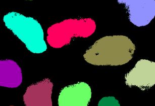
Figure 9: Schematic of the human-in-the-loop merging strategy for generating ground truth data sets
from classic image segmentation workflow results for training subsequent 3D deep learning models. Two
different classic image segmentation workflows were applied to the same lamin B1 images. One
workflow worked well on interphase lamin B1 localization patterns (yellow) and the other worked better
on mitotic lamin B1 localization patterns (cyan). A mask made up of four circles with two different radii
was manually created in Fiji with the “PaintBrush” tool. A single ground truth image was then mergedYou can also read