I am Not Afraid of the Jammer: Navigating with Signals of Opportunity in GPS-Denied Environments
←
→
Page content transcription
If your browser does not render page correctly, please read the page content below
I am Not Afraid of the Jammer:
           Navigating with Signals of Opportunity
                in GPS-Denied Environments
                                   Zak M. Kassas, Joe Khalife, and Ali Abdallah
                                       University of California, Irvine, USA
                                                    Chiawei Lee
                                       US Air Force Test Pilot School, USA

BIOGRAPHIES

Zaher (Zak) M. Kassas is an associate professor at the University of California, Irvine and director of the Autonomous
Systems Perception, Intelligence, and Navigation (ASPIN) Laboratory. He received a B.E. in Electrical Engineering
from the Lebanese American University, an M.S. in Electrical and Computer Engineering from The Ohio State
University, and an M.S.E. in Aerospace Engineering and a Ph.D. in Electrical and Computer Engineering from The
University of Texas at Austin. In 2018, he received the National Science Foundation (NSF) Faculty Early Career
Development Program (CAREER) award, and in 2019, he received the Office of Naval Research (ONR) Young
Investigator Program (YIP) award. He is a recipient of 2018 IEEE Walter Fried Award, 2018 Institute of Navigation
(ION) Samuel Burka Award, and 2019 ION Col. Thomas Thurlow Award. He is an Associate Editor for the IEEE
Transactions on Aerospace and Electronic Systems and the IEEE Transactions on Intelligent Transportation Systems.
His research interests include cyber-physical systems, estimation theory, navigation systems, autonomous vehicles,
and intelligent transportation systems.

Joe Khalife is a postdoctoral fellow at the University of California, Irvine and member of the Autonomous Systems
Perception, Intelligence, and Navigation (ASPIN) Laboratory. He received a B.E. in Electrical Engineering, an M.S.
in Computer Engineering from the Lebanese American University (LAU) and a Ph.D. in Electrical Engineering and
Computer Science from the University of California, Irvine. From 2012 to 2015, he was a research assistant at LAU,
and has been a member of the ASPIN Laboratory since 2015. He is a recipient of the 2016 IEEE/ION Position,
Location, and Navigation Symposium (PLANS) Best Student Paper Award and the 2018 IEEE Walter Fried Award.
His research interests include opportunistic navigation, autonomous vehicles, and software-defined radio.

Ali A. Abdallah is a Ph.D student in the Department of Electrical Engineering and Computer Science at the University
of California, Irvine and a member of the Autonomous Systems Perception, Intelligence, and Navigation (ASPIN)
Laboratory. He received a B.E. in Electrical Engineering from the Lebanese American University (LAU). His current
research interests include opportunistic navigation, software-defined radio, long-term evolution (LTE), 5G, and indoor
localization.

Chiawei (Wei) Lee is an Instructor Flight Test Engineer at the United States Air Force Test Pilot School. His primary
role is as Director of the school’s Test Management Program which executes about a dozen real-world flight test
projects a year. He also serves as the Chief Test Safety Officer and Flight Test Foundations Branch Chief for USAF
TPS. His previous flight test experience includes weapons and electronic warfare testing on the F-16, F-22, F-35,
B-1, and B-2. He received a B.S. in Aerospace Engineering from the University of California at Los Angeles and an
M.S. in Aeronautics and Astronautics from Stanford University.

ABSTRACT

I am not afraid of the GPS jammer, as long as there are ambient signals of opportunity (SOPs) to exploit in the
environment. In environments where GPS signals are challenged (e.g., indoors and deep urban canyons) and denied
(e.g., under jamming and spoofing attacks), SOPs could serve as an alternative navigation source to GPS, and more
generally, to global navigation satellite systems (GNSS). This paper presents a radio simultaneous localization and
mapping (radio SLAM) approach that enables the exploitation of SOPs for resilient and accurate navigation. Radio

Copyright c 2020 by Z. Kassas, J. Khalife,                             Preprint of the 2020 ION GNSS+ Conference
A. Abdallah, and C. Lee                                                  St. Louis, Missouri, September 21–25, 2020
SLAM estimates the states of the navigator-mounted receiver simultaneously with the SOPs’ states. Radio SLAM
could produce an SOP-derived navigation solution in a standalone fashion or by fusing SOPs with sensors (e.g., inertial
measurement unit (IMU), lidar, etc.), digital maps, and/or other signals (e.g., GNSS). The paper also overviews a
core component of radio SLAM: a cognitive software-defined radio (SDR) called MATRIX: Multichannel Adaptive
TRansceiver Information eXtractor, which produces navigation observables from terrestrial and space-based SOPs.
Next, the paper showcases the most accurate navigation results to-date with terrestrial and space-based SOPs from
low Earth orbit (LEO) satellites in different environments and on different platforms: indoor pedestrian, ground
vehicles in urban and deep urban canyons, and aerial vehicles. Finally, the paper presents the first ever published
experimental results for navigation with SOPs in a GPS-denied environment. These experiments took place at
Edwards Air Force Base, California, USA, during which GPS was intentionally jammed with jamming-to-signal
(J/S) ratio as high as 90 dB. The results showcase a ground vehicle traversing a trajectory of about 5 km in 180
seconds in the GPS-jammed environment, during which a GPS-IMU system drifted from the vehicle’s ground truth
trajectory, resulting in a position root mean-squared error (RMSE) of 238 m. In contrast, the radio SLAM approach
with a single cellular long-term evolution (LTE) SOP whose position was poorly known (an initial uncertainty on
the order of several kilometers) achieved a position RMSE of 32 m.

I. INTRODUCTION

Global navigation satellite systems (GNSS) are at the heart of numerous technologies that fuel our modern day
life. It is estimated that there are currently about 8 billion GNSS devices worldwide, reaching 9 billion by 2025
[1]. The economic benefits of GPS to the U.S. private sector between 1984 and 2017 is estimated to be nearly
$1.8 trillion [2], and 15 of the 18 U.S. critical infrastructures rely on GPS [3]. While losing accurate positioning,
navigation, and timing (PNT) can be a nuisance in non-safety critical applications, the impact can be catastrophic
in safety-critical applications, such as transportation, aviation, military operations, among others. Over the last few
years, GNSS jamming [4] and spoofing [5] incidents have been happening with increasing frequency, exposing the
inherent vulnerabilities of GNSS, and rendering them a single point of failure. GNSS jamming and spoofing have
disrupted airport operations in the United States [6]; affected hundreds of vessels and airplanes in South Korea [7];
disrupted navigation over South China sea islands [8]; caused chaos on smartphones and rideshares in Moscow [9];
put tens of vessels into disarray in the Black Sea [10]; caused dozens of UAVs to plummet during a Hong Kong air
show, resulting in hundreds of thousands of dollars in damages [11]; are suspected to have been utilized to hijack
unmanned aerial vehicles (UAVs) and oil tankers in the Persian Gulf [12]; and are becoming commonplace in military
conflicts [13]. What is particularly alarming is that jamming and spoofing are no longer confined to sophisticated
rogue organizations [14, 15], with jammers being sold online and marketed as personal privacy devices [16], and
hackers publishing spoofing SDR code online [17]. It is no surprise that the White House issued in February 2020
an Executive Order on “Strengthening National Resilience through Responsible Use of Positioning, Navigation, and
Timing Services” [18].

Today’s navigation systems, particularly those onboard ground and aerial vehicles, fuse information from a GNSS
receiver and an inertial measurement unit (IMU). The integration of these two systems, typically referred to as
a GNSS-aided inertial navigation system (INS), takes advantage of the complementary properties of each system:
the long-term stability of a GNSS navigation solution aids the short-term accuracy of an INS. Current trends
to supplement a navigation system in the inevitable event that GNSS signals become unreliable are traditionally
sensor-based (e.g., cameras, lasers, sonar, and odometers). These sensors could be used to extract relative motion
information to reduce the INS’s error divergence rate. However, they are still dead-reckoning-type sensors; therefore,
during prolonged periods of GNSS outage, the error will eventually diverge. Moreover, these sensors only provide
local position estimates, may not properly function in all environments (e.g., fog, snow, rain, dust, nighttime, etc.),
and are still susceptible to malicious spoofing attacks [19].

Recently, signals of opportunity (SOPs) have been considered to enable navigation whenever GNSS signals become
unavailable or unreliable [20–22]. SOPs are ambient radio signals that are not intended for navigation or timing
purposes, such as AM/FM radio [23–25], cellular [26–33], digital television [34–37], low Earth orbit (LEO) satellite
signals [38–44], and Wi-Fi [45–49]. In contrast to the aforementioned dead-reckoning-type sensors, absolute position
information may be extracted from SOPs to provide bounded INS errors. Moreover, many SOPs are practically
unaffected by dense smoke, fog, rain, snow, and other poor weather conditions.
SOPs enjoy several inherently desirable attributes for navigation purposes: (i) abundance in most locales of interest,
(ii) transmission at a wide range of frequencies and directions, (iii) reception at a carrier-to-noise ratio that is
commonly tens of dBs higher than that of GNSS signals, and (iv) they are free to use, since their infrastructure is
already operational. However, unlike GNSS, whose satellite states are transmitted in their navigation message, the
states of SOPs, namely their position and clock states, are typically unknown a priori and must be estimated. To
overcome this challenge, a radio simultaneous localization and mapping (radio SLAM) framework was proposed in
which the states of the navigating vehicle are simultaneously estimated with the states of the SOPs, while aiding
the INS in a tightly-couple fashion [50–52]. Recent work have demonstrated meter-level-accurate navigation with
SOPs on ground vehicles and pedestrians indoors [53–58] and centimeter-level accurate navigation on aerial vehicles
[59–61]. With appropriately designed navigation receivers and estimation frameworks, SOPs have been exploited as
aiding sources for INS [62, 63] and lidar [64, 65].

While recent work has demonstrated experimentally the efficacy of SOPs as PNT sources in a standalone fashion
(i.e., without fusing SOPs with any other signals or sensors) and in an integrated fashion (i.e., with fusing SOPs with
INS and lidar), experiments were never conducted in actual GNSS-denied environments. The navigation results in
such work were achieved by “fictitiously” cutting GNSS signals from the navigation filter. In September 2019, the
Autonomous Systems Perception, Intelligence, and Navigation (ASPIN) Laboratory was invited to participate in live
GPS jamming experiments at Edwards Air Force Base (AFB), California, USA, called Developmental Test Navigation
Festival (DT NAVFEST). Several experiments with stationary antennas and ground vehicles were conducted to study
SOPs for PNT. This paper reports findings from these jamming experiments. In particular, the paper analyzes the
clock errors of terrestrial SOPs within the jamming region. Moreover, the paper showcases the efficacy of the radio
SLAM approach on a ground vehicle navigating in the GPS-denied environment, while exploiting terrestrial SOPs.
The experimental results show the vehicle navigating in a jammed GPS region for 5 km in 180 seconds, during which
the position root mean-squared error (RMSE) of a traditional GPS-aided INS grew to nearly 238 m, while the radio
SLAM approach final position RMSE was around 32 m. To the authors’ knowledge, these are the first published
results in the literature of navigation with SOPs in real GPS-denied environments, under jamming conditions.

The rest of the paper is organized as follows. Section overviews the radio SLAM framework and the cognitive SDR
used to exploit terrestrial and space-based SOPs for PNT. Section III presents experimental navigation results with
terrestrial and space-based SOPs from LEO satellites in different environments and on different platforms: ground
vehicles in urban and deep urban canyons, aerial vehicles, and indoor pedestrian. Section IV describes the GPS-
jammed environment at Edwards AFB and the experimental setup. Section V presents PNT experimental results in
the GPS-jammed environment. Section VI gives concluding remarks.

II. RADIO SLAM

This section overviews radio SLAM and the cognitive SDR used to exploit terrestrial and space-based SOPs for PNT.

A. Framework Overview

Radio SLAM estimates the states of the navigator-mounted receiver simultaneously with the SOPs’ states. Observ-
ability of radio SLAM was analyzed in [66–69], leading to establishing the minimal a priori knowledge needed about
the navigator-mounted receiver’s and/or SOP transmitters’ states. Radio SLAM could produce an SOP-derived nav-
igation solution in a standalone fashion [27, 28, 32, 55, 59] or by fusing SOPs with sensors (e.g., inertial measurement
unit (IMU) [51, 52, 62], lidar [64, 65], etc.), digital maps [63, 70], and/or signals (e.g., GNSS [27, 71, 72]). Fig. 1
illustrates a high-level block diagram of radio SLAM.

B. MATRIX Cognitive SDR

MATRIX (Multichannel Adaptive TRansceiver Information eXtractor) is a state-of-the-art, cognitive SDR, developed
at the ASPIN Laboratory, for navigation with terrestrial and space-based SOPs. MATRIX continuously searches
for opportune signals from which it draws navigation and timing information, employing signal characterization
on-the-fly as necessary. Fig. 2 shows the architecture of MATRIX.
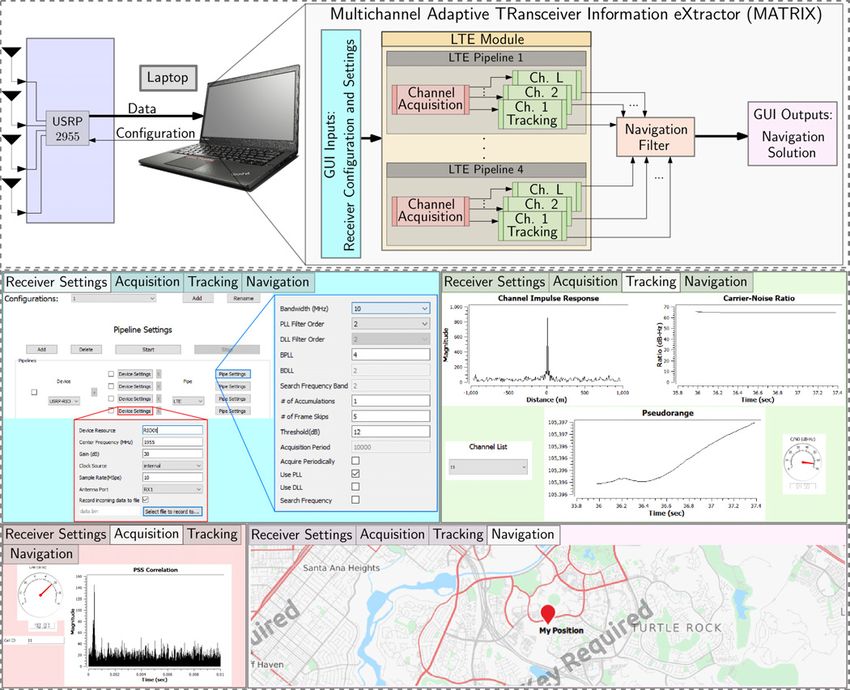
IMU   Lidar      other
                                                                                      sensors

                                           GNSS      Estimates                                  Navigation
                                                        or
                                          receiver pseudoranges/        Navigation               solution
                                                      carrier phase       filter:
                                          SOP                             Estimates
                                         receiver pseudoranges/         vehicle's state
                                                      carrier phase                             Updated
                                                                             and
                                                SOP                    unmapped SOPs             SOP
                                                map                                              map

                                                                            Road
                                                                            map
                                                       Fig. 1. Radio SLAM framework.

                           Data

                        Configuration

                           Data

                        Configuration

                           Data

                        Configuration

    USRP: universal software radio peripheral      GUI: graphical user interface     IMU: inertial measurement unit   : antenna
      CDMA: code division multiple access           LTE: long-term evolution         LEO: low earth orbit

                                                 Fig. 2. MATRIX cognitive SDR architecture.

III. NAVIGATION WITH TERRESTRIAL AND LEO SATELLITE SOPS

The radio SLAM framework with MATRIX has been validated experimentally with terrestrial SOPs (cellular code
division multiple access (CDMA), LTE, and 5G) and space-based SOPs from LEO satellites (Orbcomm and Iridium
constellations) in different environments and on different platforms: ground vehicles in urban and deep urban canyons,
aerial vehicles, and indoor pedestrian. This section illustrates these navigation results, which are considered the most
accurate to-date for navigation with SOPs.

A. Ground Vehicle Navigation

A.1 Navigation with Standalone LTE SOPs

Fig. 3 shows the navigation performance with standalone LTE signals in an urban environment in Riverside, Califor-
nia, USA, on a ground vehicle [32]. Here, the positions of the LTE towers (also known as eNodeBs) were pre-surveyed
and the radio SLAM framework did not estimate these positions, but it estimated the eNodeBs’ clock errors along
with the ground vehicle’s position and velocity. The ground vehicle traversed a trajectory of 1.44 km, achieving a
position RMSE of 3.17 m with four eNodeBs. The ground truth was obtained from the GPS navigation solution,
produced from 10 GPS satellites.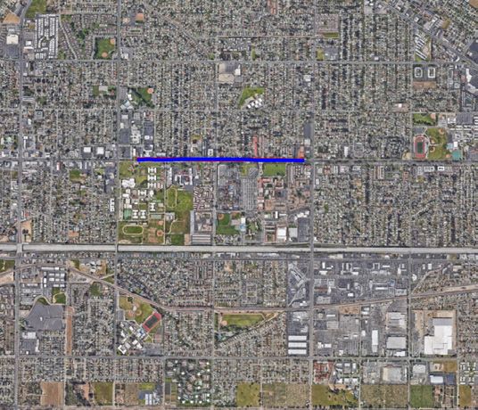
Fig. 3. Ground vehicle navigation with LTE SOPs in an urban environment in downtown Riverside, California, USA. This figure
shows the environmental layout, the four LTE eNodeBs’ locations, and the traversed trajectory. Over a trajectory of 1.44 km, the LTE
navigation solution exhibited a position RMSE of 3.17 m, standard deviation of 1.06 m, and maximum error of 6.58 m from the GPS
navigation solution obtained with 10 GPS satellites [32]. Map data: Google Earth.

A.2 Navigation with GPS, LTE, IMU, and Map Matching

Fig. 4 shows the navigation performance with an integrated navigation system, which used GPS and LTE SOPs
along with an IMU and map matching in a deep urban environment in downtown Riverside, California, USA, on a
ground vehicle [63]. The positions of the LTE eNodeBs were pre-surveyed and the radio SLAM framework did not
estimate these positions, but it estimated the eNodeBs’ clock errors along with the INS’s states. The ground truth
was obtained with a Septentrio AsteRx-i V integrated GPS–IMU system, which was equipped with a dual-antenna
multi-frequency GNSS receiver and a Vectornav VN-100 microelectromechanical system IMU. The carrier phase
observables recorded by the Septentrio system were fused with nearby differential GPS base stations’ measurements
to produce the carrier phase-based real-time kinematic (RTK) solution [73]. Due to non-line-of-sight, the vehicle
encountered 15 seconds of a GPS unavailability period, causing the GPS-IMU solution to accumulate errors due to
IMU drift, resulting in a position RMSE of 5.1 m. In contrast, exploiting two LTE eNodeBs in the environment and
employing map matching, reduced the position RMSE by 33%, achieving 3.43 m.

A.3 Navigation with LEO Satellite SOPs and IMU

Fig. 5 shows the navigation performance with LEO-aided INS. Here, the radio SLAM framework is more complex
due to the poorly known and dynamic, stochastic nature of LEO satellites. The navigation framework is termed
STAN: simultaneous tracking and navigation, to emphasize the fact that LEO satellites are tracked in their orbit.
The ground vehicle traversed a trajectory of 7,495 m in 258 seconds along Interstate 5 in Orange County, California,
USA, achieving a position RMSE of 188.6 m when using LEO-aided INS with periodic LEO satellite position updates
(transmitted by the LEO satellites) and 195.6 m without satellite position updates (LEO satellite states estimated
from two-line element (TLE) files and orbit propagation algorithms), compared to a position RMSE of 1,419 m when
using the INS only [74]. The ground truth was obtained using the Septentrio AsteRx-i V integrated GPS–IMU
system discussed in Subsection III-A.2.
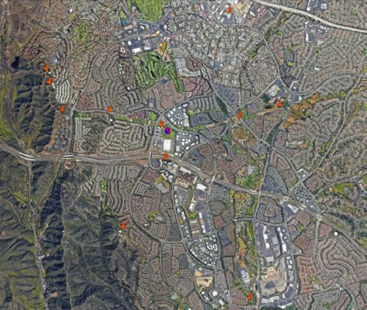
Fig. 4. Ground vehicle navigation with an integrated navigation system, which used GPS and LTE SOPs along with an IMU and
map matching in a deep urban environment in downtown Riverside, California, USA. The figure shows the environmental layout, LTE
eNodeBs’ locations, traversed trajectory, and the different navigation solutions. Over a trajectory of 345 m, the GPS-LTE-IMU with
map matching exhibited a position RMSE of 3.43 m compared to 5.1 m achieved using GPS-IMU only [63]. Map data: Google Earth.

                                            Trajectories:

Fig. 5. Ground vehicle navigation with LEO satellite-aided INS in Orange County, California, USA. The figure shows the trajectory
of the two Orbcomm LEO satellites, estimated trajectory of one of the satellites and corresponding final position uncertainty, and true
and estimated trajectories of the ground vehicle. Over a trajectory of 7,495 m in 258 seconds, the LEO-aided INS exhibited a position
RMSE of 188.6 m when using LEO-aided INS with periodic LEO satellite position updates (transmitted by LEO satellites) and 195.6 m
without satellite position updates, compared to a position RMSE of 1,419 m with INS only [74]. Map data: Google Earth.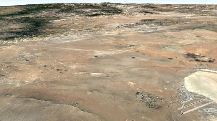
B. Aerial Vehicle Navigation

B.1 Navigation with Standalone CDMA and LTE SOPs

On aerial vehicles and exploiting carrier phase observables, sub-meter level-accurate navigation with standalone
cellular CDMA and LTE SOPs can be achieved. Fig. 6 shows the navigation performance with cellular CDMA
SOPs for a UAV flown in Colton, California, USA [60]. Here, the positions of the CDMA towers (also known as base
transceiver stations (BTSs)) were pre-surveyed and the radio SLAM framework did not estimate these positions.
These results were obtained via a carrier phase differential cellular (CD-cellular) CDMA navigation framework. The
navigation solution exhibited a two-dimensional (2-D) position RMSE of 62.11 cm over a trajectory of 1.72 km flown
in 3 minutes. The solution from the UAV’s onboard integrated navigation system was used as ground truth.

                                                                                        GPS Antenna

                                                                                      Cellular Antenna

                                                                                           Ettus E312
                                                                                                USRP

Fig. 6. UAV navigation results with CD-cellular CDMA SOPs in Colton, California, USA [60]. The figure shows the environmental
layout, CDMA BTSs’ locations, true trajectory (from the UAV’s onboard integrated navigation system), and the carrier phase differential
cellular (CD-cellular) CDMA navigation solution in the base/rover framework. The CD-cellular navigation solution exhibited a position
RMSE of 62.11 cm over a trajectory of 1.72 km flown over a period of 3 minutes. Map data: Google Earth.

Fig. 7 shows the navigation performance with standalone cellular LTE SOPs for a UAV flown in Mission Viejo,
California, USA [61]. The figure shows the environmental layout, LTE eNodeBs’ locations, true trajectory (from a
Septentrio AsteRx-i V GNSS-INS with RTK system), and the carrier phase LTE navigation solution. An altimeter
was used in the navigation framework to estimate the UAV’s altitude. In contrast to the results shown in Fig. 6,
no base was used here. The navigation solution exhibited a 2-D and 3-D position RMSE of 81 cm and 86 cm,
respectively, for a traversed trajectory of 605 m over 175 seconds.

B.2 Navigation with CDMA SOPs and IMU

Fig. 8 shows the navigation performance with standalone cellular CDMA SOPs for a UAV flown in Riverside,
California, USA [52]. The figure shows the environmental layout, CDMA SOPs’ locations, true trajectory (from
UAV’s onboard integrated navigation system), and the cellular CDMA SOP-aided INS navigation solution. In
contrast to the results shown in Fig. 6 and 7, this experiment (1) did not assume knowledge of the SOPs’ locations:
the positions of these SOPs were simulataneously estimated in a radio SLAM fashion, (2) utilized an INS, and (3)
used SOP pseudorange measurements.

B.3 Navigation with LEO Satellite SOPs and IMU

Fig. 9 shows experimental results of a UAV navigating via the LEO-aided INS in Irvine, California, USA. The UAV
exhibited a final position error of 5.7 m (with LEO satellite position updates) and 29.9 m (without LEO satellite
position updates– here, LEO satellite states were estimated from TLE files and orbit propagation algorithms),
compared to 123.5 m with an INS only [42].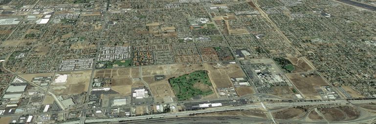
Fig. 7. UAV navigation results with LTE SOPs in Mission Viejo California, USA [61]. This figure shows the environmental layout, LTE
eNodeBs’ locations, experimental setup, UAV’s true trajectory (obtained using a Septentrio AsteRx-i V GNSS-INS with RTK system),
and the carrier phase LTE navigation solution. The UAV traversed a trajectory of 605 m over 175 seconds. The results show a 2-D
position RMSE of 81 cm and a 3-D position RMSE of 86 cm. Map data: Google Earth.

                               Estimated SOP location       True SOP location
Fig. 8. UAV navigation results with cellular CDMA SOP-aided INS in Riverside California, USA for 80 seconds, the last 30 seconds
of which were without GPS [52]. (a) Experimental environment showing the UAV’s trajectory, cellular SOPs’ locations, initial SOPs’
position uncertainties, and final position uncertainties. (b) UAV’s trajectory before and after GPS cutoff: (i) white: ground truth, (ii)
green: SOP-aided INS before GPS cutoff, (iii) blue: SOP-aided INS after GPS cutoff, and (iv) red: GPS aided INS after GPS cutoff, i.e.,
INS only. (c) and (d) True and estimated SOP locations and corresponding final uncertainty ellipses. Map data: Google Earth.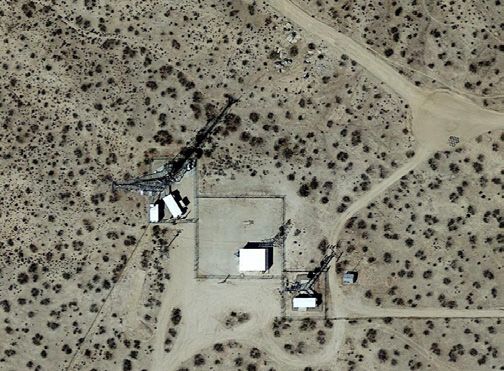
Fig. 9. UAV navigation with LEO satellite-aided INS in Irvine, California, USA, for 155 seconds, the last 30 seconds of which were
without GPS [42]. This figure shows: the trajectory of the two Orbcomm LEO satellites, zoom on the UAV’s final position and final
position estimates, and true and estimated trajectories of the UAV. Map data: Google Earth.

B.4 Navigation with Standalone LEO Satellite SOPs

Fig. 10 shows experimental results of a UAV navigating with carrier phase differential LEO (CD-LEO) satellite
signals in Mission Viejo, California, USA [75]. This framework employs a rover and a base receiver. In contrast to
the results presented in Fig. 9, no INS was used here. Also, no LEO satellite position updates were used, instead,
the LEO satellite states were estimated from TLE files and orbit propagation algorithms. The UAV traversed a
trajectory of 2.2 km, achieving a 2-D position RMSE of 15.03 m.

Fig. 10. UAV navigation results with CD-LEO satellite signals in Mission Viejo, California, USA [75]. Here, the UAV (acted as the
rover) and a stationary receiver (acted as the base). This figure shows trajectory of the two Orbcomm LEO satellites, true trajectory of
the UAV (rover), and the estimated trajectory of the rover using CD-LEO. The UAV traversed a trajectory of 2.2 km, achieving a 2-D
position RMSE of 15.03 m. Google Earth.
C. Pedestrian Indoor Navigation

Indoor environments are particularly challenging for SOP-based navigation due to severe signal attenuation and
multipath effects. Nevertheless, LTE SOPs have shown tremendous potential in indoor environments, with MATRIX
being able to acquire and track LTE signals deep inside buildings, in rooms without windows, and on different floors
[76].

Fig. 11(a) shows the navigation performance with LTE SOPs, coupled with a synthetic aperture navigation (SAN)
framework to minimize multipath effects by utilizing beamforming. The LTE-SAN navigation solution demonstrated
a 2-D position RMSE of 3.93 m compared to 7.19 m from standalone LTE (without SAN) over a traversed trajectory
of 126.8 m in 100 seconds and while listening to six LTE eNodeBs [57]. Fig. 11(b) shows the navigation performance
of an LTE-aided IMU. The LTE-IMU navigation solution exhibited a 2-D position RMSE of 2.92 m compared to
5.09 m and 9.48 m from standalone LTE and standalone IMU, respectively, for a traversed trajectory of 109 m over
50 seconds and while listening to five LTE eNodeBs [58]. In both experiments, the LTE eNodeBs locations were
pre-surveyed.

                                                                           30
                       0

                      -10                                                  20

                      -20
                                                                           10
              y [m]

                                                                   y [m]

                      -30
                                                                            0
                      -40

                      -50                                                  -10

                      -60
                                                                           -20

                            0      20           40    60                         -20   -10   0    10     20   30   40
                                        x [m]                                                    x [m]

Fig. 11. (a) Pedestrian indoor navigation with LTE SOP signals, at the University of California, Irvine, USA [57]. The figure shows
the pedestrian’s ground truth trajectory versus the navigation solution from: (i) standalone LTE (without SAN) and (ii) LTE-SAN. (b)
Pedestrian indoor navigation with LTE SOP signals and IMU, at the University of California, Riverside, USA [58]. The figure shows the
pedestrian’s ground truth trajectory versus the navigation solution from: (i) standalone LTE (without IMU) and (ii) LTE-IMU.

IV. GPS-JAMMED ENVIRONMENT AND EXPERIMENTAL SETUP

All SOP-based experimental results presented in Section III were conducted in environments in which GPS signals
were not jammed. Essentially, GPS signals were “fictitiously” cut off from the navigation filter. In September 2019,
the ASPIN Laboratory was invited to conduct experiments during DT NAVFEST live GPS jamming at Edwards
AFB, California, USA. This section overviews the GPS-jammed environment and experimental setup.

A. Jamming Laydown

From the information made available to the participants, six high-powered jammers (HPJ) and one portable box
jammer (PBJ) were spread over an area of approximately 50 miles north of Edwards AFB, as shown in Fig. 12.
The term “Hx” denotes an HPJ, one of them seen in Fig. 12, and “Nx” denotes a PBJ. The initial locations and
characteristics of the jammers are summarized in Table I. The experiments conducted by the ASPIN team took place
just outside the perimeters of Edwards AFB, mainly on the 58 Highway pictured in Fig. 12 and near the Mojave
airport.
TABLE I
Jammer Laydown
Latitude Longitude Terrain Antenna Antenna Antenna Antenna EIRP
Site Wave-
(N) (W) height height azimuth elevation gain (dBi) (dBm)
(ft MSL) (ft AGL) true (deg) form
(deg) L1 L2 L1 L2
Hx1 35◦ 04′ 12.4” 118◦ 08′ 41.82” 2769 10 57 15 24.2 24.5 83.8 84.1 CW,
BBN
Hx2 34◦ 59′ 43.52” 117◦ 52′ 42.35” 2313 10 15 15 24.2 24.5 83.8 84.1 CW,
BBN
Hx3 34◦ 59′ 45.57” 117◦ 51′ 52.65” 2289 10 13 15 24.2 24.5 83.8 84.1 CW,
BBN
Hx4 35◦ 02′ 59.59” 118◦ 01′ 40.87” 2528 10 43 15 24.2 24.5 83.8 84.1 CW,
BBN
Hx5 34◦ 57′ 29.35” 117◦ 57′ 31.78” 2429 10 24 15 24.2 24.5 83.8 84.1 CW,
BBN
Hx6 34◦ 57′ 30.83” 117◦ 54′ 12.65” 2441 10 17 15 24.2 24.5 83.8 84.1 CW,
BBN
Nx1 34◦ 54′ 42.45” 117◦ 54′ 5.5” 2309 29 49 -30 14.1 12.9 -12.4 -13.6 CW,
BBN
MSL: Mean sea level
AGL: Above ground level
dBi: Decibel isotropic
dBm: Decibel referenced to 1 milliwatt
EIRP: Equivalent, isotropically radiated power. EIRP values accounted for estimated 1.5 dB line loss between amplifier and antenna
CW: Continuous wave
BBN: broad-band noise
B. SOP LTE eNodeB Layout
An SOP radio mapping campaign with MATRIX was conducted a month before DT NAVFEST to survey available
LTE eNodeBs in the area [77]. Since Edwards AFB is largely unpopulated, only two LTE eNodeBs (SOP 1 and
SOP 2) were hearable in the scheduled jamming area and were located at the same site, as shown in Fig. 13. The
eNodeBs were transmitting at high power to service large macrocells in the sparsely populated area. The eNodeBs
corresponded to two U.S. cellular providers, and they were transmitting on dual frequencies. The characteristics of
the two eNodeBs are summarized in Table II.
TABLE II
eNodeBs’ Characteristics
Cell
eNodeB Carrier frequency [MHz] NID Cellular provider
1 751/2125 377 Verizon
2 731.5/2145 491 T-Mobile
C. Hardware Setup
The hardware setup used in the performed experiment included: (i) Septentrio GNSS-INS system and (ii) LTE
front-end, which are described next.
C.1 Septentrio GNSS-INS System
The Septentrio GNSS-INS system consists of: (i) a multi-frequency GNSS AsteRx-i V receiver, a tactical-grade
Vectornav VN-100 micro-electromechanical system (MEMS) IMU, and a dual-GNSS antenna system. AsteRx-i V
processes the dual antenna multi-frequency GNSS signals with IMU measurements to generate an accurate and
reliable position and orientation solution. Multi-GNSS antennas 1 and 2 were mounted on a wooden board that
was mounted on the roof of the vehicle and aligned with the vehicle’s main axis. Antenna-1, i.e., the main antenna,
was toward the back of the vehicle. Antenna-2, i.e., the auxiliary antenna, was toward the front of the vehicle. The
VN-100 IMU was mounted on the wooden board as well, with its x-axis pointing toward the front of the vehicle, they-axis pointing to the right of the vehicle (as seen from behind the vehicle), and the z-axis pointing downward. It
is worth noting that only GPS was jammed, while signals from other GNSS constellations (Galileo and GLONASS)
were available. The GNSS-INS system was used to obtain the vehicle’s ground truth trajectory by using signals from
the non-jammed GNSS constellations.
Edwards, CA
5 km
58 Highway
Fig. 12. DT NAVFEST GPS jamming layout. Map data: Google Earth.
C.2 LTE Front-End
The LTE front-end comprised: (i) a quad-channel universal software radio peripheral (USRP)-2955, (ii) two consumer-
grade 800/1900 MHz Laird cellular antennas [78], (iii) a PCIe cable, (iv) a laptop, and (v) a consumer-grade GPS
antenna to discipline the USRP’s onboard GPS-disciplined oscillator (GPSDO). The two Laird antennas were con-
nected to the USRP to capture impinging LTE signals, and the USRP was tuned to listen to two carrier frequencies
corresponding to the eNodeBs in Table II.Fig. 13. SOP LTE eNodeB layout.
Fig. 14. Ground vehicle and hardware setup.
D. Software Setup
The software setup used in the performed experiment included: (i) Septentrio’s post-processing software development
kit and (ii) MATRIX, which are described next.
D.1 Septentrio PPSDK Tool
Septentrio’s post-processing software development kit (PP-SDK) was used to process GNSS observables collected
by the AsteRx-i V to obtain a GNSS-INS navigation solution. This integrated GNSS-INS system [73] was used to
produce the ground truth results with which the produced navigation solution was compared.D.2 MATRIX: LTE-Module
The conducted experiment used the MATRIX SDR’s carrier-aided code phase-based LTE module to produce navi-
gation observables from received LTE signals. Fig. 15 shows the GUI front panel of the LTE module of MATRIX.
Data
Configuration
Fig. 15. GUI of the LTE module of the MATRIX SDR.
V. PNT EXPERIMENTAL RESULTS IN GPS-JAMMED ENVIRONMENT
Two experiments were conducted to study the behavior of SOPs in the presence of real GPS jamming and to assess
their potential as PNT sources. The results from each experiment are presented next.
A. Experiment 1: Stationary Receiver
Cellular CDMA BTSs and LTE eNodeBs are typically equipped with GPSDOs to meet the synchronization require-
ments set by the 3GPP [79]. Some opportunistic navigation frameworks exploit the resulting stability of cellular
SOPs’ clocks [59,61,80]. It is therefore important to evaluate the clock stability of cellular SOPs under GPS jamming
to determine their suitability in the opportunistic frameworks discussed in Section III.A.1 Setup The setup described in Subsections IV-C and IV-D was deployed outside of the jamming area to listen to the two LTE eNodeBs (SOP 1 and SOP 2) located in an area affected by jamming. The J/S at the eNodeBs was around 60 dBs. During this experiment, the jammers were periodically turned on for 10 minutes, then turned off for 2 minutes. The MATRIX SDR sampled LTE signals synchronously at 10 Msps for 95 minutes on carrier frequencies 751 MHz and 731.5 MHz, which are frequencies allocated to U.S. cellular providers Verizon Wireless and T-Mobile, respectively. Fig. 16 shows the setup of the first experiment. Fig. 16. Experiment 1 setup. The setup discussed in Subsections IV-C and IV-D was deployed outside of the GPS-jammed area to listen to the two SOPs located in an area where J/S was around 60 dB. Map data: Google Earth. A.2 Results The LTE signal samples were processed by the LTE module of MATRIX to produce pseudorange observables to the two eNodeBs. Since both the eNodeBs and the receiver were stationary, the variations in the resulting pseudoranges were mainly due to the relative clock biases between the eNodeBs and the receiver. Fig. 17(a) shows the time history of the SOPs’ clock biases, which were obtained from their pseudoranges after subtracting the initial pseudorange values. Note that a 5-minute dataloss occurred around the 35th minutes due to a hardware malfunction. After a short initial transient due to the receiver’s GPSDO, the clock biases seem to stabilize. Moreover, both clock biases appear to be driven by a common term, which is likely to be the receiver’s bias. To evaluate the relative stability between the SOP biases, the difference of the biases (without subtracting their initial values) is plotted in Fig. 17(b), which shows a stable difference around hovering around 1835 m. Fig. 17 does not show significant correlation between the stability of the clock biases and the jamming window, leading to the conclusion that the LTE SOPs’ relative stability is maintained for a period of more than an hour during GPS jamming. This could be attributed to either: (i) the oscillators equipped on the towers are disciplined by other GNSS constellations or (ii) the free-running oscillators remained stable during the jamming period. B. Experiment 2: Mobile Receiver A second experiment was conducted to demonstrate the radio SLAM framework with real LTE signals under real GPS jamming. The experimental setup and results are discussed next.
Fig. 17. Experiment 1 results. (a) Time history of clock biases corresponding to SOP 1 and SOP 2. The initial pseudorange values
were subtracted. A hardware malfunction around the 35th minute caused a 5-minute dataloss. (b) Clock bias difference between SOP 1
and SOP 2, without subtracting the initial pseudoranges. The stable difference shows that the relative stability between LTE SOPs is
maintained for a period of more than an hour during GPS jamming.
B.1 Setup
In this experiment, a ground vehicle was driven in the East direction along the 58 Highway, shown in Fig. 12.
Over the course of the experiment, only one LTE eNodeB (SOP 1) was hearable at 751 MHz. LTE samples were
collected at 10 Msps for 8 minutes. The vehicle started west of the jamming area, and entered the jamming area
around 30 seconds after LTE signal collection started. Then, 10 seconds later, GPS signals became intermittent,
after which they were completely lost 10 seconds later. GPS became available again 130 seconds later. During this
experiment, the jammers were operating continuously. Two radio SLAM scenarios were considered: (i) the SOP
position was assumed to be fully known (from the prior mapping campaign) and (ii) the SOP position was assumed
to be unknown, (a prior with a large uncertainty was used). In both scenarios, an EKF was used to produce an
estimate of the receiver’s and SOP’s states from SOP pseudorange measurements. Statistical models were used to
propagate the receiver’s and SOP’s state estimates between GPS or SOP updates. The results are presented next.
B.2 Results
Results from a smartphone navigation application are provided first for comparison. Screenshots from Google Maps
running on an iPhone 8 during the ground vehicle’s trajectory are shown in Fig. 18. Essentially, the navigation
solution stopped updating, would sporadically jump around by hundreds of meters, and the blue “halo” representing
the estimated position uncertainty grew to a radius over 6 km.
Fig. 18. Screenshots from Google Maps on an iPhone 8 during Experiment 2. The uncertainty grew to a radius over 6 km.
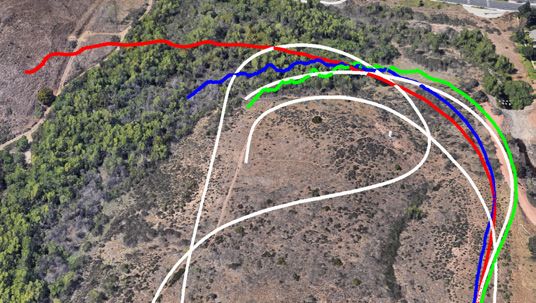
In both radio SLAM scenarios, the receiver had access to GPS signals for the first 50 seconds only. For the SLAM
with known SOP position scenario, the SOP position was assumed to be fully known. The receiver’s 2-D position
RMSE was found to be 29.4 m with a final 2-D position error of 69.4 m. For the radio SLAM with unknown
SOP position scenario, the SOP initial position was poorly known. In particular, the SOP position was randomly
initialized around the true SOP position with an initial 2-D ±3σ radius of 3.3 km. For the random realization usedin the EKF, the initial SOP position error was 1.07 km. The receiver’s final 2-D position RMSE was found to be
32.2 m with a final 2-D position error of 84.5 m. Table III and Fig. 19 summarize the results of Experiment 2. For
comparison, a GPS-IMU solution was produced using Septentrio’s PPSDK tool for the same trajectory as the radio
SLAM scenarios. The receiver’s 2-D position RMSE was found to be 237.9 m from the GPS-IMU solution with a
final 2-D position error of 766.0 m.
TABLE III
Experiment 2 Results
Framework Receiver RMSE (m) Receiver final error (m) SOP final error (m)
Radio SLAM with 29.4 69.4 –
known SOP position
Radio SLAM with 32.2 84.5 5.2
unknown SOP position
GPS-IMU 237.9 766.0 –
VI. CONCLUSION
This paper justified why I am not afraid of the GPS jammer, as long as there are ambient SOPs to exploit in
the environment. This paper presented a radio SLAM approach that enables the exploitation of SOPs for resilient
and accurate navigation in environments where GPS signals are challenged (e.g., indoors and deep urban canyons)
or denied (e.g., under jamming and spoofing attacks). Radio SLAM could produce an SOP-derived navigation
solution in a standalone fashion or by fusing SOPs with sensors (e.g., IMU, lidar, etc.), digital maps, and/or other
signals (e.g., GNSS). The paper overviewed MATRIX, a cognitive SDR, which produces navigation observables from
terrestrial and space-based SOPs. The paper showcased the most accurate navigation results to-date with terrestrial
and space-based SOPs from LEO satellites in different environments and on different platforms: ground vehicles
in urban and deep urban canyons, aerial vehicles, and indoor pedestrian. Moreover, the the paper presented the
first ever published experimental results for navigation with SOPs in a GPS-denied environment. These experiments
took place at Edwards AFB, California, USA, during DT NAVFEST, in which GPS was intentionally jammed with
J/S as high as 90 dB. The results analyzed the clock stability of two cellular SOP LTE eNodeBs in the jammed
area, showing that the relative stability between the LTE SOPs is maintained for a period of more than an hour
during GPS jamming. Moreover, the results showcased a ground vehicle traversing a trajectory of about 5 km in 180
seconds in the GPS-jammed environment, during which a GPS-IMU system drifted from the vehicle’s ground truth
trajectory, resulting in a position RMSE of 238 m. In contrast, the radio SLAM approach with a single cellular LTE
SOP whose position was poorly known (an initial uncertainty on the order of several kilometers) achieved a position
RMSE of 32 m.
ACKNOWLEDGMENTS
The authors would like to thank Edwards AFB for inviting the ASPIN Laboratory to conduct experiments during DT
NAVFEST. The authors would like to thank Joshua Morales, Kimia Shamaei, Mahdi Maaref, Kyle Semelka, MyLinh
Nguyen, and Trier Mortlock for their help with data collection. This work was supported in part by the Office of
Naval Research (ONR) under Grant N00014-19-1-2511 and Grant N00014-19-1-2613; in part by the National Science
Foundation (NSF) under Grant 1929965; and in part by the U.S. Department of Transportation (USDOT) under
University Transportation Center (UTC) Program Grant 69A3552047138. DISTRIBUTION STATEMENT A.
Approved for public release; Distribution is unlimited 412TW-PA-20399.Fig. 19. Experiment 2 layout and results for both scenarios: (i) fully known SOP position and (ii) unknown SOP position.
References
[1] European GNSS Agency (GSA), “GNSS market report,” https://www.gsa.europa.eu/system/files/reports/gnss mr 2017.pdf, May
2017.
[2] RTI International, “Economic benefits of the Global Positioning System,” https://www.rti.org/sites/default/files/gps
finalreport.pdf, June 2019.
[3] M. Graham, “GPS use in U.S. critical infrastructure and emergency communications,” https://www.gps.gov/multimedia/
presentations/2012/10/USTTI/graham.pdf, October 2012.
[4] D. Borio, F. Dovis, H. Kuusniemi, and L. L. Presti, “Impact and detection of GNSS jammers on consumer grade satellite navigation
receivers,” Proceedings of the IEEE, vol. 104, no. 6, pp. 1233–1245, February 2016.
[5] M. Psiaki and T. Humphreys, “GNSS spoofing and detection,” Proceedings of the IEEE, vol. 104, no. 6, pp. 1258–1270, June 2016.
[6] S. Pullen and G. Gao, “GNSS jamming in the name of privacy: Potential threat to GPS aviation,” Inside GNSS, pp. 34–43,
March/April 2012.
[7] Inside GNSS News, “North Korea’s GPS jamming prompts South Korea to endorse nationwide eLoran system,” http://
www.insidegnss.com/node/3532, April 2013.
[8] Sputnik News, “China jams US spy drones over disputed South China Sea islands,” https://sputniknews.com/us/
201505221022471108/, May 2015.[9] C. Sebastian, “Getting lost near the Kremlin? Russia could be ‘GPS spoofing’,” http://money.cnn.com/2016/12/02/technology/
kremlin-gps-signals/index.html, December 2016.
[10] Inside GNSS News, “Reports of mass GPS spoofing attack in the Black Sea strengthen calls for PNT backup,” https://
insidegnss.com/reports-of-mass-gps-spoofing-attack-in-the-black-sea-strengthen-calls-for-pnt-backup/, July 2017.
[11] D. Divis, “Dozens of drones crash after GPS jammed causing HK$1M in damages, criminal investigation launched,” https://
insideunmannedsystems.com/dozens-of-drones-crash-after-gps-jammed-causing-hk1m-in-damages-criminal-investigation-launched,
October 2018.
[12] Inside GNSS, “Iran is reportedly jamming ship GPS navigation systems to get them to wander into Iranian waters,” https://
www.businessinsider.com/iran-is-jamming-ship-gpsnavigation-systems-to-seize-them-2019-8, August 2019.
[13] O. Pawlyk, “General: Electronic jamming a growing problem for aircraft in Syria,” https://www.military.com/dodbuzz/2018/04/
30/general-electronic-jamming-growing-problem-aircraft-syria.html, April 2018.
[14] J. Bhatti and T. Humphreys, “Hostile control of ships via false GPS signals: Demonstration and detection,” NAVIGATION, Journal
of the Institute of Navigation, vol. 64, no. 1, pp. 51–66, 2017.
[15] Inside GNSS, “Tesla Model S and Model 3 prove vulnerable to GPS spoofing attacks, research from Regulus cyber
shows,” https://insidegnss.com/tesla-model-s-and-model-3-prove-vulnerable-to-gps-spoofing-attacks-research-from-regulus-cyber-
shows, June 2019.
[16] GPS World, “FCC to fine Chinese jammer retailer $34.9m for online U.S. sales,” http://gpsworld.com/fcc-to-fine-chinese-jammer-
retailer-34-9m-for-online-u-s-sales, June 2014.
[17] GPS World, “Inexpensive hack spoofs GPS in smartphones, drones,” http://gpsworld.com/inexpensive-hack-spoofs-gps-in-
smartphones-drones, August 2015.
[18] United States, Executive Office of the President, “Executive order on strengthening national resilience through responsible use of
positioning, navigation, and timing services,” Febraury 2020.
[19] J. Petit, B. Stottelaar, M. Feiri, and F. Kargl, “Remote attacks on automated vehicles sensors: Experiments on camera and lidar,”
Black Hat Europe, vol. 11, 2015.
[20] J. Raquet and R. Martin, “Non-GNSS radio frequency navigation,” in Proceedings of IEEE International Conference on Acoustics,
Speech and Signal Processing, March 2008, pp. 5308–5311.
[21] L. Merry, R. Faragher, and S. Schedin, “Comparison of opportunistic signals for localisation,” in Proceedings of IFAC Symposium
on Intelligent Autonomous Vehicles, September 2010, pp. 109–114.
[22] Z. Kassas, “Collaborative opportunistic navigation,” IEEE Aerospace and Electronic Systems Magazine, vol. 28, no. 6, pp. 38–41,
2013.
[23] J. McEllroy, J. Raquet, and M. Temple, “Use of a software radio to evaluate signals of opportunity for navigation,” in Proceedings
of ION GNSS Conference, September 2006, pp. 126–133.
[24] A. Popleteev, “Indoor positioning using FM radio signals,” Ph.D. dissertation, University of Trento, Italy, 2011.
[25] M. Psiaki and B. Slosman, “Tracking of digital FM OFDM signals for the determination of navigation observables,” in Proceedings
of ION GNSS Conference, September 2019, pp. 2325–2348.
[26] C. Yang and T. Nguyen, “Tracking and relative positioning with mixed signals of opportunity,” NAVIGATION , Journal of the
Institute of Navigation, vol. 62, no. 4, pp. 291–311, December 2015.
[27] Z. Kassas, J. Khalife, K. Shamaei, and J. Morales, “I hear, therefore I know where I am: Compensating for GNSS limitations with
cellular signals,” IEEE Signal Processing Magazine, pp. 111–124, September 2017.
[28] J. Khalife and Z. Kassas, “Navigation with cellular CDMA signals – part II: Performance analysis and experimental results,” IEEE
Transactions on Signal Processing, vol. 66, no. 8, pp. 2204–2218, April 2018.
[29] J. del Peral-Rosado, J. López-Salcedo, F. Zanier, and G. Seco-Granados, “Position accuracy of joint time-delay and channel estimators
in LTE networks,” IEEE Access, vol. 6, no. 25185–25199, p. April, 2018.
[30] J. del Peral-Rosado, R. Raulefs, J. López-Salcedo, and G. Seco-Granados, “Survey of cellular mobile radio localization methods:
From 1G to 5G,” IEEE Communications Surveys Tutorials, vol. 20, no. 2, pp. 1124–1148, 2018.
[31] C. Gentner, “Channel-SLAM: Multipath assisted positioning,” Ph.D. dissertation, Ulm University, 2018.
[32] K. Shamaei and Z. Kassas, “LTE receiver design and multipath analysis for navigation in urban environments,” NAVIGATION ,
Journal of the Institute of Navigation, vol. 65, no. 4, pp. 655–675, December 2018.
[33] A. Abdallah, K. Shamaei, and Z. Kassas, “Assessing real 5g signals for opportunistic navigation,” in Proceedings of ION GNSS
Conference, 2020, accepted.
[34] M. Rabinowitz and J. Spilker, Jr., “A new positioning system using television synchronization signals,” IEEE Transactions on
Broadcasting, vol. 51, no. 1, pp. 51–61, March 2005.
[35] P. Thevenon, S. Damien, O. Julien, C. Macabiau, M. Bousquet, L. Ries, and S. Corazza, “Positioning using mobile TV based on
the DVB-SH standard,” NAVIGATION , Journal of the Institute of Navigation, vol. 58, no. 2, pp. 71–90, 2011.
[36] J. Yang, X. Wang, M. Rahman, S. Park, H. Kim, and Y. Wu, “A new positioning system using DVB-T2 transmitter signature
waveforms in single frequency networks,” IEEE Transactions on Broadcasting, vol. 58, no. 3, pp. 347–359, September 2012.
[37] L. Chen, O. Julien, P. Thevenon, D. Serant, A. Pena, and H. Kuusniemi, “TOA estimation for positioning with DVB-T signals in
outdoor static tests,” IEEE Transactions on Broadcasting, vol. 61, no. 4, pp. 625–638, 2015.
[38] L. Gill, D. Grenier, and J. Chouinard, “Use of XM radio satellite signal as a source of opportunity for passive coherent location,”
IET Radar, Sonar Navigation, vol. 5, no. 5, pp. 536–544, June 2011.
[39] D. Lawrence, H. Cobb, G. Gutt, M. OConnor, T. Reid, T. Walter, and D. Whelan, “Navigation from LEO: Current capability and
future promise,” GPS World Magazine, vol. 28, no. 7, pp. 42–48, July 2017.
[40] T. Reid, A. Neish, T. Walter, and P. Enge, “Broadband LEO constellations for navigation,” NAVIGATION, Journal of the Institute
of Navigation, vol. 65, no. 2, pp. 205–220, 2018.
[41] R. Landry, A. Nguyen, H. Rasaee, A. Amrhar, X. Fang, and H. Benzerrouk, “Iridium Next LEO satellites as an alternative PNT in
GNSS denied environments–part 1,” Inside GNSS Magazine, pp. 56–64., May 2019.
[42] Z. Kassas, J. Morales, and J. Khalife, “New-age satellite-based navigation – STAN: simultaneous tracking and navigation with LEO
satellite signals,” Inside GNSS Magazine, vol. 14, no. 4, pp. 56–65, 2019.
[43] J. Khalife, M. Neinavaie, and Z. Kassas, “Navigation with differential carrier phase measurements from megaconstellation LEO
satellites,” in Proceedings of IEEE/ION Position, Location, and Navigation Symposium, April 2020, pp. 1393–1404.
[44] Z. Kassas, J. Khalife, M. Neinavaie, and T. Mortlock, “Opportunity comes knocking: overcoming GPS vulnerabilities with other
satellites’ signals,” Inside Unmanned Systems Magazine, pp. 30–35, June/July 2020.[45] J. Khalife, Z. Kassas, and S. Saab, “Indoor localization based on floor plans and power maps: Non-line of sight to virtual line of
sight,” in Proceedings of ION GNSS Conference, September 2015, pp. 2291–2300.
[46] R. Faragher and R. Harle, “Towards an efficient, intelligent, opportunistic smartphone indoor positioning system,” NAVIGATION ,
Journal of the Institute of Navigation, vol. 62, no. 1, pp. 55–72, 2015.
[47] A. Makki, A. Siddig, M. Saad, and C. Bleakley, “Survey of WiFi positioning using time-based techniques,” Computer Networks,
vol. 88, pp. 218–233, 2015.
[48] Y. Zhuang, Z. Syed, Y. Li, and N. El-Sheimy, “Evaluation of two WiFi positioning systems based on autonomous crowdsourcing of
handheld devices for indoor navigation,” IEEE Transactions on Mobile Computing, vol. 15, no. 8, pp. 1982–1995, August 2016.
[49] Z. Zhang, S. He, Y. Shu, and Z. Shi, “A self-evolving WiFi-based indoor navigation system using smartphones,” IEEE Transactions
on Mobile Computing, vol. 19, no. 8, pp. 1760–1774, 2020.
[50] Z. Kassas, “Analysis and synthesis of collaborative opportunistic navigation systems,” Ph.D. dissertation, The University of Texas
at Austin, USA, 2014.
[51] J. Morales, P. Roysdon, and Z. Kassas, “Signals of opportunity aided inertial navigation,” in Proceedings of ION GNSS Conference,
September 2016, pp. 1492–1501.
[52] J. Morales and Z. Kassas, “Tightly-coupled inertial navigation system with signals of opportunity aiding,” IEEE Transactions on
Aerospace and Electronic Systems, 2019, submitted.
[53] C. Yang, T. Nguyen, and E. Blasch, “Mobile positioning via fusion of mixed signals of opportunity,” IEEE Aerospace and Electronic
Systems Magazine, vol. 29, no. 4, pp. 34–46, April 2014.
[54] M. Driusso, C. Marshall, M. Sabathy, F. Knutti, H. Mathis, and F. Babich, “Vehicular position tracking using LTE signals,” IEEE
Transactions on Vehicular Technology, vol. 66, no. 4, pp. 3376–3391, April 2017.
[55] K. Shamaei, J. Khalife, and Z. Kassas, “Exploiting LTE signals for navigation: Theory to implementation,” IEEE Transactions on
Wireless Communications, vol. 17, no. 4, pp. 2173–2189, April 2018.
[56] K. Shamaei, J. Morales, and Z. Kassas, “A framework for navigation with LTE time-correlated pseudorange errors in multipath
environments,” in Proceedings of IEEE Vehicular Technology Conference, April 2019, pp. 1–6.
[57] A. Abdallah, K. Shamaei, and Z. Kassas, “Indoor localization with LTE carrier phase measurements and synthetic aperture antenna
array,” in Proceedings of ION GNSS Conference, September 2019, pp. 2670–2679.
[58] A. Abdallah, K. Shamaei, and Z. Kassas, “Performance characterization of an indoor localization system with LTE code and carrier
phase measurements and an IMU,” in Proceedings of International Conference on Indoor Positioning and Indoor Navigation,
September 2019, pp. 1–8.
[59] J. Khalife and Z. Kassas, “Precise UAV navigation with cellular carrier phase measurements,” in Proceedings of IEEE/ION Position,
Location, and Navigation Symposium, April 2018, pp. 978–989.
[60] J. Khalife, K. Shamaei, S. Bhattacharya, and Z. Kassas, “Centimeter-accurate UAV navigation with cellular signals,” in Proceedings
of ION GNSS Conference, September 2018, pp. 2321–2331.
[61] K. Shamaei and Z. Kassas, “Sub-meter accurate UAV navigation and cycle slip detection with LTE carrier phase,” in Proceedings
of ION GNSS Conference, September 2019, pp. 2469–2479.
[62] Z. Kassas, J. Morales, K. Shamaei, and J. Khalife, “LTE steers UAV,” GPS World Magazine, vol. 28, no. 4, pp. 18–25, April 2017.
[63] Z. Kassas, M. Maaref, J. Morales, J. Khalife, and K. Shamaei, “Robust vehicular localization and map matching in urban envi-
ronments through IMU, GNSS, and cellular signals,” IEEE Intelligent Transportation Systems Magazine, vol. 12, no. 3, pp. 36–52,
June 2020.
[64] J. Khalife, S. Ragothaman, and Z. Kassas, “Pose estimation with lidar odometry and cellular pseudoranges,” in Proceedings of IEEE
Intelligent Vehicles Symposium, June 2017, pp. 1722–1727.
[65] M. Maaref, J. Khalife, and Z. Kassas, “Lane-level localization and mapping in GNSS-challenged environments by fusing lidar data
and cellular pseudoranges,” IEEE Transactions on Intelligent Vehicles, vol. 4, no. 1, pp. 73–89, March 2019.
[66] Z. Kassas and T. Humphreys, “Observability analysis of collaborative opportunistic navigation with pseudorange measurements,”
IEEE Transactions on Intelligent Transportation Systems, vol. 15, no. 1, pp. 260–273, February 2014.
[67] Z. Kassas and T. Humphreys, “Receding horizon trajectory optimization in opportunistic navigation environments,” IEEE Trans-
actions on Aerospace and Electronic Systems, vol. 51, no. 2, pp. 866–877, April 2015.
[68] J. Morales and Z. Kassas, “Stochastic observability and uncertainty characterization in simultaneous receiver and transmitter
localization,” IEEE Transactions on Aerospace and Electronic Systems, vol. 55, no. 2, pp. 1021–1031, April 2019.
[69] J. Khalife and Z. Kassas, “Opportunistic UAV navigation with carrier phase measurements from asynchronous cellular signals,”
IEEE Transactions on Aerospace and Electronic Systems, vol. 56, no. 4, pp. 3285–3301, August 2020.
[70] M. Maaref and Z. Kassas, “Ground vehicle navigation in GNSS-challenged environments using signals of opportunity and a closed-
loop map-matching approach,” IEEE Transactions on Intelligent Transportation Systems, pp. 1–16, June 2019.
[71] M. Maaref and Z. Kassas, “UAV integrity monitoring measure improvement using terrestrial signals of opportunity,” in Proceedings
of ION GNSS Conference, September 2019, pp. 3045–3056.
[72] M. Maaref, J. Khalife, and Z. Kassas, “Enhanced safety of autonomous driving by incorporating terrestrial signals of opportunity,”
in Proceedings of IEEE International Conference on Acoustics, Speech and Signal Processing, May 2020, pp. 9185–9189.
[73] “Septentrio AsteRx-i V,” https://www.septentrio.com/products, 2018.
[74] C. Ardito, J. Morales, J. Khalife, A. Abdallah, and Z. Kassas, “Performance evaluation of navigation using LEO satellite signals with
periodically transmitted satellite positions,” in Proceedings of ION International Technical Meeting Conference, 2019, pp. 306–318.
[75] J. Khalife and Z. Kassas, “Assessment of differential carrier phase measurements from orbcomm LEO satellite signals for opportunistic
navigation,” in Proceedings of ION GNSS Conference, September 2019, pp. 4053–4063.
[76] A. Abdallah, K. Shamaei, and Z. Kassas, “Indoor positioning based on LTE carrier phase measurements and an inertial measurement
unit,” in Proceedings of ION GNSS Conference, September 2018, pp. 3374–3384.
[77] J. Morales and Z. Kassas, “Optimal collaborative mapping of terrestrial transmitters: receiver placement and performance charac-
terization,” IEEE Transactions on Aerospace and Electronic Systems, vol. 54, no. 2, pp. 992–1007, April 2018.
[78] “Laird phantom 3G/4G multiband antenna NMO mount white TRA6927M3NB,” https://www.lairdtech.com/products/phantom-
series-antennas.
[79] 3GPP2, “Recommended minimum performance standards for cdma2000 spread spectrum base stations,” 3rd Generation
Partnership Project 2 (3GPP2), TS C.S0010-E, March 2014. [Online]. Available: http://www.arib.or.jp/english/html/overview/
doc/STD-T64v7 00/Specification/ARIB STD-T64-C.S0010-Ev2.0.pdf
[80] J. Khalife and Z. Kassas, “Evaluation of relative clock stability in cellular networks,” in Proceedings of ION GNSS Conference,
September 2017, pp. 2554–2559.You can also read