UNITED STATES AIR FORCE AIRCRAFT ACCIDENT INVESTIGATION BOARD REPORT
←
→
Page content transcription
If your browser does not render page correctly, please read the page content below
UNITED STATES AIR FORCE
AIRCRAFT ACCIDENT INVESTIGATION
         BOARD REPORT

               F-35A, T/N 10-5015
         58TH FIGHTER SQUADRON
            33D FIGHTER WING
      EGLIN AIR FORCE BASE, FLORIDA

 LOCATION: EGLIN AIR FORCE BASE, FLORIDA
      DATE OF ACCIDENT: 23 JUNE 2014
BOARD PRESIDENT: COLONEL GREGORY KEETON
    Conducted IAW Air Force Instruction 51-503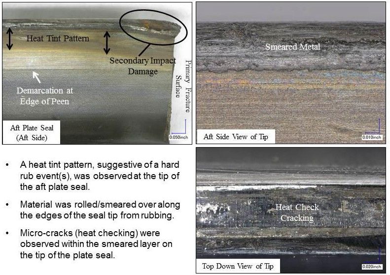
EXECUTIVE SUMMARY
                           AIRCRAFT ACCIDENT INVESTIGATION

                                     F-35A, T/N 10-5015
                              EGLIN AIR FORCE BASE, FLORIDA
                                        23 JUNE 2014

On 23 June 2014, at approximately 0910 hours local time, the mishap aircraft (MA), an F-35A,
tail number 10-5015, assigned to the 58th Fighter Squadron, 33d Fighter Wing, Eglin Air Force
Base (AFB), experienced an engine stall and subsequent fire during takeoff roll. The Mishap
Pilot (MP) aborted the takeoff, stopped on the runway and safely egressed the still burning
aircraft. Emergency crews responded and extinguished the fire. There was no damage to private
property and minor airfield damage. The MA engine sustained significant damage and the aft
(rear) two thirds of the MA sustained significant fire damage. While total costs as a result of this
mishap have yet to be determined, damages to the mishap aircraft have been estimated to be in
excess of $50,000,000.00.

The Accident Investigation Board (AIB) president found, by clear and convincing evidence, that
the cause of the mishap was a material failure of the third stage Integrally Bladed Rotor forward
integral arm. Pieces of this rotor arm ejected through the upper portion of the aircraft fuselage,
which severed internal fuel and hydraulic lines. The fuel and hydraulic fluid ignited and the
ensuing fire encompassed the aircraft around the area where the fuselage was penetrated and aft
as the MP aborted the takeoff. The MP performed an engine shut down and egressed, and the
leaking fluids continued to burn on and around the aircraft. The fire was extinguished
approximately seven minutes after the initial indications of a fire.

Under 10 U.S.C. § 2254(d) the opinion of the accident investigator as to the cause of, or the factors
contributing to, the accident set forth in the accident investigation report, if any, may not be considered
as evidence in any civil or criminal proceeding arising from the accident, nor may such information be
considered an admission of liability of the United States or by any person referred to in those conclusions
or statements.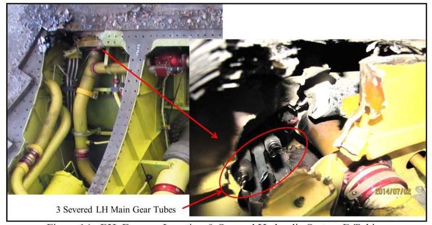
SUMMARY OF FACTS AND STATEMENT OF OPINION
                             F-35A, T/N 10-5015
                               23 JUNE 2014

                                                TABLE OF CONTENTS
TABLE OF CONTENTS…………………………………………………………………………. i
COMMONLY USED
ACRONYMS AND ABBREVIATIONS ...................................................................................... iii
SUMMARY OF FACTS ................................................................................................................ 1
  1. AUTHORITY AND PURPOSE ...........................................................................................1
     a. Authority .........................................................................................................................1
     b. Purpose............................................................................................................................1
  2. ACCIDENT SUMMARY.....................................................................................................1
  3. BACKGROUND ..................................................................................................................1
     a. Air Education and Training Command (AETC) .............................................................2
     b. 33d Fighter Wing (33 FW) .............................................................................................2
     c. 33d Operations Group (33 OG).......................................................................................2
     d. 58th Fighter Squadron (58 FS) .......................................................................................2
     e. F-35A – Lightning II .......................................................................................................2
  4. SEQUENCE OF EVENTS ...................................................................................................3
     a. Mission ............................................................................................................................3
     b. Planning ..........................................................................................................................3
     c. Preflight ...........................................................................................................................3
     d. Summary of Accident .....................................................................................................4
     e. Impact ..............................................................................................................................4
     f. Egress and Aircrew Flight Equipment (AFE) .................................................................4
     g. Search and Rescue (SAR) ...............................................................................................4
     h. Recovery of Remains ......................................................................................................5
  5. MAINTENANCE .................................................................................................................5
     a. Forms Documentation .....................................................................................................5
     b. Inspections ......................................................................................................................5
     c. Maintenance Procedures .................................................................................................6
     d. Maintenance Personnel and Supervision ........................................................................6
     e. Fuel, Hydraulic, and Oil Inspection Analyses ................................................................6
     f. Unscheduled Maintenance ...............................................................................................7
  6. AIRFRAME, MISSILE, OR SPACE VEHICLE SYSTEMS ..............................................7
     a. Structures and Systems ...................................................................................................7
         (1) Engine..................................................................................................................... 7
         (2) Hydraulic system .................................................................................................. 11
         (3) Fuel System .......................................................................................................... 12
         (4) Electrical System .................................................................................................. 12
         (5) Airframe Structure and Skin ................................................................................ 13
     b. Evaluation and Analysis ...............................................................................................13
         (1) Analysis 1 – Engine R3 Failure............................................................................ 13

                                               F-35A, T/N 10-5015, 23 June 2014
                                                              i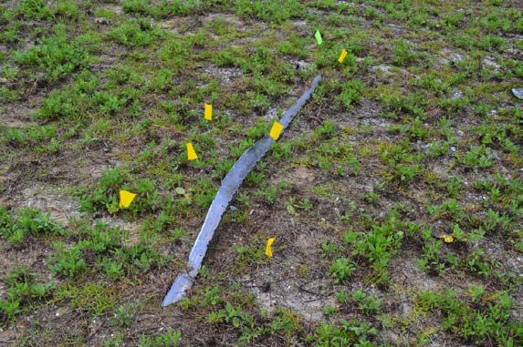
(2) Analysis 2 – Fire .................................................................................................. 20
   7. WEATHER .........................................................................................................................21
       a. Forecast Weather ...........................................................................................................21
       b. Observed Weather .........................................................................................................21
       c. Space Environment .......................................................................................................21
       d. Operations .....................................................................................................................21
   8. CREW QUALIFICATIONS ...............................................................................................21
       a. Mishap Pilot ..................................................................................................................21
   9. MEDICAL ..........................................................................................................................22
       a. Qualifications ................................................................................................................22
       b. Health ............................................................................................................................22
       c. Toxicology ....................................................................................................................22
       d. Lifestyle ........................................................................................................................22
       e. Crew Rest and Crew Duty Time ...................................................................................23
   10. OPERATIONS AND SUPERVISION .............................................................................23
       a. Operations .....................................................................................................................23
       b. Supervision ...................................................................................................................23
   11. HUMAN FACTORS ........................................................................................................23
   12. GOVERNING DIRECTIVES AND PUBLICATIONS ...................................................24
       a. Publically Available Directives and Publications Relevant to the Mishap ...................24
       b. Other Directives and Publications Relevant to the Mishap ..........................................24
       c. Known or Suspected Deviations from Directives or Publications ................................25
   13. ADDITIONAL AREAS OF CONCERN .........................................................................25
STATEMENT OF OPINION ....................................................................................................... 26
   1. Opinion Summary ...............................................................................................................26
   2. Cause ...................................................................................................................................26
   3. Conclusion ..........................................................................................................................27
INDEX OF TABS ......................................................................................................................... 28

                                                F-35A, T/N 10-5015, 23 June 2014
                                                               ii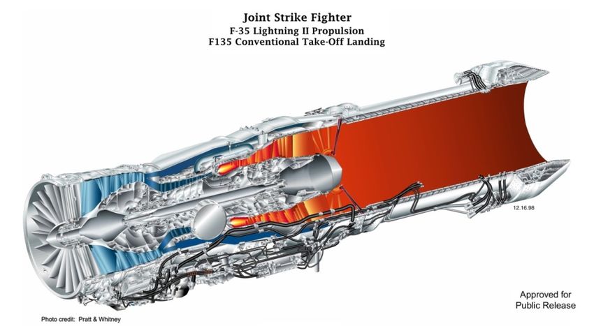
ACRONYMS AND ABBREVIATIONS

AETC        Air Education and Training Command          HYD FLUID B              Hydraulic Fluid System B
AF                                        Air Force     IAW                             In Accordance With
AFB                                  Air Force Base     IBR                         Integrally Bladed Rotor
AFE                     Aircrew Flight Equipment        ICAWS               Integrated Caution, Advisory,
AFI                           Air Force Instruction                                    and Warning System
AFM                          Airfield Management        ICC                  Inverter/Converter/Controller
AFRL               Air Force Research Laboratory        IP                                   Instructor Pilot
AIB                  Accident Investigation Board       IPP                      Integrated Power Package
AIB/LA Accident Investigation Board Legal Advisor       JTD                   Joint-Service Technical Data
AIB/MDM              Accident Investigation Board       L                                        Local Time
                                  Medical Member        LM                                 Lockheed Martin
AIB/MXM              Accident Investigation Board       MA                                  Mishap Aircraft
                             Maintenance Member         ME                                   Mishap Engine
AIB/PM Accident Investigation Board Pilot Member        MFL                              Mishap Flight Lead
AIB/R      Accident Investigation Board Recorder        MFO                                Mission Fall Out
AIMWTS     Aeromedical Information Management           MMB                        Mishap Mission Briefer
                          Waiver Tracking System        MOA                        Military Operating Area
ALIS     Autonomic Logistics Information System         MP                                      Mishap Pilot
AMU                     Aircraft Maintenance Unit       MS                                    Mishap Sortie
ASM                     Activity Security Manager       MX1                                      Crew Chief
AV                                      Air Vehicle     NOTAMs                            Notices to Airmen
BLD LEAK ENG                    Bleed Leak Engine       OG                                Operations Group
BMC                         Basic Mission Capable       ORM                 Operational Risk Management
BOS                   Before Operations Servicing       P&W                               Pratt and Whitney
CAPS                    Critical Action Procedures      PAIR Production Aircraft Inspection Requirements
CCT                             Crew Chief Trainer      PHA                    Periodic Health Assessment
CEMP     Combined Emergency Management Plan             POS                      Post Operations Servicing
CMMS     Computerized Maintenance Management            psi                        Pounds Per Square Inch
                                             System     PWL                        Pratt and Whitney Legal
CSMU               Crash Survivable Memory Unit         PWPM         Pratt and Whitney Program Manager
CTOL           Conventional Takeoff and Landing         PWT                 Pratt and Whitney Technician
CT                           Continuation Training      QC                                    Quality Check
DoD                         Department of Defense       R3                                Third Stage Rotor
EFH                            Engine Flight Hours      RAP                        Ready Aircrew Program
ENG STALL                               Engine Stall    RAPCON                Radar Approach and Control
F/C                                       Fire Chief    RWY                                          Runway
F/L EX                        Flight Line Expediter     S2                              Second Stage Stator
FLT SUR                              Flight Surgeon     SAR                              Search and Rescue
FOD                        Foreign Object Damage        SHM                Squadron Health Management’
FS                                Fighter Squadron      SII                            Special Interest Item
FSE                              Flight Safety NCO      SOF                            Supervisor of Flying
FW                                    Fighter Wing      TCTD      Time Compliance Technical Directives
g                               Gravitational Force     TDY                                Temporary Duty
HCF                             High Cycle Fatigue      T/N                                     Tail Number
HFACS Human Factors Analysis and Classification         T.O.                                Technical Order
                                             System     USAF                        United States Air Force
HIT                         Health Inspection Task

The above list was compiled from the Summary of Facts, the Statement of Opinion, the Index of
Tabs, and Witness Testimony (Tabs R, V).

                                     F-35A, T/N 10-5015, 23 June 2014
                                                    iii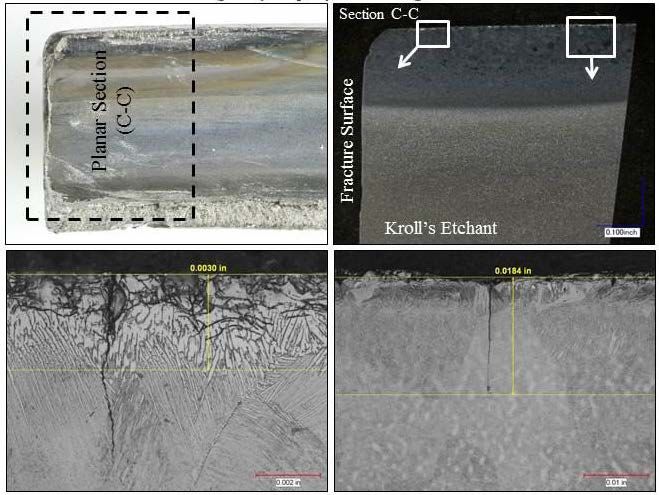
SUMMARY OF FACTS

1. AUTHORITY AND PURPOSE

   a. Authority

On 30 July 2014, Major General Leonard A. Patrick, Vice Commander, Air Education and
Training Command (AETC), appointed Colonel Gregory S. Keeton to conduct an aircraft
accident investigation of a mishap that occurred on 23 June 2014 involving an F-35A aircraft,
tail number (T/N) 10-5015, at Eglin Air Force Base (AFB), Florida (FL). The aircraft accident
investigation was conducted by the assembled Board at Eglin AFB, FL from 13 August 2014
through 29 August 2014 in accordance with Air Force Instruction (AFI) 51-503, Aerospace
Accident Investigations. During the recessed period from 30 August 2014 through 26 February
2015, the Board recessed pending completion of the policy reviews of technical data and
information collected as part of the Board’s investigation for determination of compliance with
the Arms Export Control Act and claimed proprietary privileges. This report only pertains to the
immediate causes of the 23 June 2014 mishap and uses technical information available during
the investigation by the assembled Board at Eglin AFB in August 2014 (Tabs J-2 thru J-11, J-13
thru J-89, J-90 thru J-146, J-147-J-166 and J-167). Board members included a Legal Advisor
(Lieutenant Colonel), a Medical Member (Major), a Pilot Member (Captain), a Maintenance
Member (Master Sergeant), and a Recorder (Technical Sergeant).

   b. Purpose

This is a legal investigation convened to inquire into the facts surrounding the aircraft or
aerospace accident on 23 June 2014, to prepare a publicly releasable report, and to gather and
preserve all available evidence for use in litigation, claims, disciplinary actions, administrative
proceedings, and for other purposes. .

2. ACCIDENT SUMMARY
On 23 June 2014, at approximately 0910 hours local time (L), the mishap aircraft (MA), an F-
35A, T/N 10-5015, assigned to the 58th Fighter Squadron (FS), 33d Fighter Wing (FW), Eglin
AFB, FL, experienced an engine stall and subsequent fire during takeoff roll. The Mishap Pilot
(MP) aborted the takeoff, stopped on the runway and safely egressed the still burning aircraft.
Emergency crews responded and extinguished the fire. (Tab V-2.5, J-4 thru J-5). There was no
damage to private property and minor airfield damage. The MA engine sustained significant
damage and the aft (rear) two thirds of the MA sustained significant fire damage. Total mishap
damage costs were estimated to be in excess of $50,000,000.00 (Tabs P-20, P-25).

3. BACKGROUND
The MA belonged to the 58 FS, 33d Operations Group (OG), 33 FW, Air Education and
Training Command, stationed at Eglin AFB, FL (Tabs CC-3 thru CC-19).

                                 F-35A, T/N 10-5015, 23 June 2014
                                                1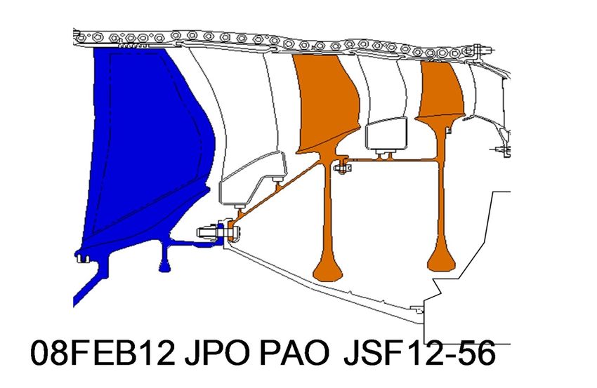
a. Air Education and Training Command (AETC)

AETC’s primary mission is to recruit, train and educate Airmen to deliver
airpower for America. It was established and activated in January 1942,
making it the second oldest major command in the Air Force (AF) and its
training mission makes it the first command to touch the lives of nearly
every AF member. The command’s vision is to forge innovative Airmen
to power the world’s greatest AF. The command’s organization includes
the AF Recruiting Service, two numbered air forces, and the Air
University. AETC has more than 29,000 active duty members, 6,000 Air
National Guard and AF Reserve personnel, and 15,000 civilian personnel.
The command also has more than 11,000 contractors assigned. AETC flies
approximately 1,300 aircraft. (Tab CC-3).

   b. 33d Fighter Wing (33 FW)

The 33 FW is a graduate flying and maintenance training wing for the F-35
Lightning II, organized under AETC. The 33 FW is an associate unit
located on Eglin AFB, FL, which is an Air Force Materiel Command base.
The mission of the 33 FW is to train world-class F-35 pilots and
maintainers, air battle managers and intelligence personnel. The 33 FW
manages the F-35 Integrated Training Center, training F-35 pilots and
maintainers for the Air Force, Marine Corps, and Navy, as well as foreign
nations. The wing operates five squadrons with 1,500 U.S. military,
government civilian and contractor personnel assigned to the F-35
Integrated Training Center. (Tabs CC-13 thru CC-16).

   c. 33d Operations Group (33 OG)

The 33 OG is comprised of the 58th Fighter Squadron, training Air Force
pilots with the F-35A Conventional Takeoff and Landing (CTOL) variant;
the 337th Air Control Squadron, training U.S. and allied air battle
managers at Tyndall AFB; and the 33d Operations Support Squadron (Tabs
CC-13 thru CC-14).

   d. 58th Fighter Squadron (58 FS)

The 58 FS “Mighty Gorillas” are authorized to operate 24 assigned F-35A
aircraft, planning and executing a training curriculum in support of Air
Force and international partner pilot training requirements. The Gorillas
also fly two Royal Netherlands Air Force F-35As (Tabs CC-13 thru CC-
14).

   e. F-35A – Lightning II

The Lockheed Martin F-35A Lightning II Conventional Takeoff and Landing variant is the
United States Air Force’s (USAF) latest 5th generation fighter. It will bring an enhanced

                               F-35A, T/N 10-5015, 23 June 2014
                                              2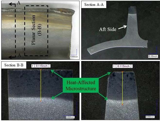
capability to survive in the advanced threat
environment in which it was designed to operate.
(Tabs CC-17 thru CC-19).

The F-35A gives the USAF and allies the power to
dominate the skies – anytime, anywhere. The F-35A is
an agile, versatile, high-performance, 9g capable
multirole fighter that combines stealth, sensor fusion,
and unprecedented situational awareness (Tab CC-17).

The F-35A’s Pratt & Whitney F135-PW-100 turbofan engine produces 43,000 pounds of thrust
and consists of a 3-stage fan, a 6-stage compressor, an annular combustor, a single stage high-
pressure turbine, and a 2-stage low pressure turbine (Tabs CC-18 thru CC-19).

4. SEQUENCE OF EVENTS

   a. Mission

The mission was scheduled as a Continuation Training two-ship sortie (a flight of two aircraft),
call sign “Thug,” to Rosehill Military Operating Area (MOA), with the MP as number 02 (Tab
K-4). Continuation Training sorties are typical training missions flown to keep pilots current in
required maneuvers, skills and tasks. In this case, two aircraft were scheduled as a formation and
the mishap pilot was in the second aircraft. Prior to the mission brief, “Thug ” flight combined
with “Eagle” flight, also a two-ship, to become a four-ship for simplicity in terms of departing
and coming back with Air Traffic Control (Tabs K-4, V-2.3). The four-ship was renamed
“Eagle” flight with the MP as number 04. Prior to takeoff, two aircraft from “Eagle” flight had
slight maintenance delays, therefore the four-ship became a two-ship, with the MP as the second
ship of the two-ship formation (Tab V-2.4). This sortie flew under the 58 FS allotment of flying
hours for instructor pilot proficiency in accordance with the F-35 Ready Aircrew Program (RAP)
Tasking Message (Tab BB-5). All USAF flying units have a yearly budget of hours for
peacetime training, and the RAP tasking message delineates what missions and types of training
are to occur (Tab BB-5).

   b. Planning

The flight lead of the four-ship, Eagle 01, mission planned the sortie prior to the briefing (Tabs
K-4, V-2.3). The briefing covered all required items in accordance with (IAW) AFI 11-2F-35v3
including Notices to Airmen (NOTAMs), Special Interest Items (SIIs), forecast weather and
planned flying events (Tab V-2.3).

   c. Preflight

Prior to flying, members of the four-ship “Eagle” flight accomplished all required Go/No-Go
items and completed an Operational Risk Management (ORM) assessment that was approved by
the Operations Supervisor (Tabs K-27, K-17). Go/No-Go items are requirements that must be
accomplished prior to flight such as reading safety notices or accomplishing required training
events. ORM assessments are made prior to every flight and take into account relevant factors

                                 F-35A, T/N 10-5015, 23 June 2014
                                                3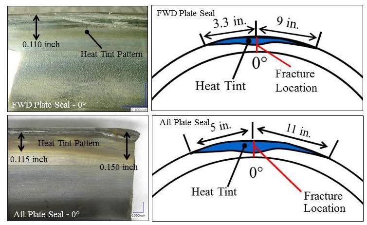
that could affect the safety of the flight to include weather, aircrew fatigue levels and complexity
of the mission. Preflight of the MA was uneventful (Tab V-2.4).

   d. Summary of Accident

On Monday, 23 June 2014, at 09:09L, the MP began a takeoff on Runway (RWY) 12 at Eglin
AFB (Tabs V-2.4, J-148). At the correct rotation speed, the MP began to rotate, or lift the nose
wheel off the ground in anticipation of takeoff. During rotation, the MA engine stalled and
displayed an ENG STALL (engine stall) Integrated Caution, Advisory, Warning (ICAW) at
09:10:06L (Tab J-82). The MP heard an audible bang and felt the aircraft decelerate about the
same time the MP received the ENG STALL ICAW and the MP subsequently applied the
ABORT procedure at 09:10:07L (Tabs J-83, V-2.4). The MP received other warnings and
cautions including FIRE FIRE (Tab V-2.4 thru V-2.5). The ENG STALL ICAW was followed
at 09:10:07L by FIRE GEAR and HYD FLUID B ICAWs (Tab J-83 thru J-84). FIRE GEAR
indicated that fire detection sensors located in the wheel wells detected fire. HYD FLUID B
indicated that the hydraulic fluid in system B was below minimum levels. As the aircraft slowed
to a stop, numerous additional ICAWs annunciated including BLD LEAK ENG, IPP FAIL and
HYD FAIL B indicating that there was hot engine exhaust detected outside of the engine and
hydraulic system B no longer had any fluid (Tabs J-80 thru J-89). The MP stopped the aircraft
approximately 8,000 feet down the runway following the abort procedure (Fig-12 below, Tab S-
9).

The MP accomplished the EGRESS procedure at approximately 09:10:38L (Tab J-86). Two
witnesses and the MP reported a visible fire and thick, black smoke around the aircraft as the MP
exited the cockpit and safely evacuated the scene (Tabs R-6, R-10, V-1.4, V-2.5).

The fire continued for approximately seven minutes spreading from an initial fire on top of the
aircraft to a ground fire fed by leaking fluids and a subsequent internal engine bay fire. The fire
damaged the aft two thirds of the aircraft before emergency responders were able to extinguish it
(Tabs J-5, J-9 thru J-10, J-80 thru J-89, S-2, S-3).

   e. Impact

Not applicable.

   f. Egress and Aircrew Flight Equipment (AFE)

The MP performed a ground egress of the F-35A without injury (Tabs J-4, V-2.5 thru 2.6, X-3).
The MP was wearing the appropriate AFE as directed by Joint Technical Data (JTD). The MP’s
helmet, sleeved flight jacket and skeletal G-suit were inspected and were deemed to have no
discrepancies or damage. (Tab X-7)

   g. Search and Rescue (SAR)

Not applicable.

                                 F-35A, T/N 10-5015, 23 June 2014
                                                 4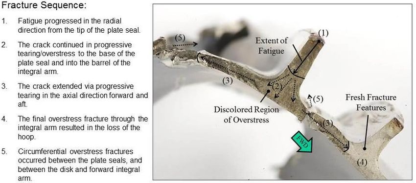
h. Recovery of Remains

Not applicable.

5. MAINTENANCE

   a. Forms Documentation

The 58th Aircraft Maintenance Unit (AMU), Eglin AFB, maintained the electronic records for
the MA. Tracking aircraft maintenance is accomplished via the Autonomic Logistics
Information System (ALIS) while the Computerized Maintenance Management System (CMMS)
application is used to document maintenance actions. Squadron Health Management (SHM) is
used to track Production Aircraft Inspection Requirements (PAIR) using the Health Inspection
Task (HIT) functionality, which is used to create, update, and track non-expired items and
maintenance inspection requirements. Time Compliance Technical Directives (TCTD) are
maintained in CMMS.

TCTD are used to process system changes, usually aircraft part upgrades, which must be
accomplished within a specific time period and by a specific date. This time period is dependent
upon the severity of the issue the TCTD addresses. A TCTD may also direct inspection or
adjustments to equipment or parts already installed on the aircraft. Time change items are
routine maintenance actions in which components are removed and replaced after a given
number of flight hours or calendar days. There were no overdue TCTDs, special inspections, or
time changes at the time of the mishap (Tab DD-10).

Before the first flight of the day for any aircraft, an Air Vehicle (AV) Exceptional Release (ER)
must be completed. An AV ER includes a review of ALIS and its supporting applications. It
serves as a certification that the authorized individual has ensured the aircraft is safe for flight.
Within ALIS, the AV Release is required before Pilot Acceptance of the aircraft. The
Production Superintendent completed an AV Release in ALIS prior to the mishap sortie (MS)
(Tab DD-9).

All scheduled inspections were completed IAW applicable Joint-Service Technical Data (JTD)
guidance with no discrepancies noted. (Tabs D-3, DD-9 thru DD-10). A detailed review of the
MA’s CMMS, SHM and TCTDs revealed no evidence to suggest maintenance forms
documentation was a factor to the mishap (Tabs DD-9 thru DD-10).

   b. Inspections

A Before Operations Servicing (BOS) Inspection is a flight preparedness inspection performed
by maintenance personnel prior to flight and is valid for 24 hours once completed. BOS
Inspections are performed IAW JTD module F35-AAA-A1321010000-281A-A. The purpose of
the BOS Inspection is to visually inspect various areas, operationally check various systems, and
check fluid levels of the aircraft in preparation for a flying period. The last BOS Inspection was
completed on 23 June 2014 at 0217L with no defects noted (Tab D-3). As part of the BOS
Inspection, an Engine BOS Inspection was completed on 23 June 2014 at 0111L IAW JTD

                                  F-35A, T/N 10-5015, 23 June 2014
                                                 5
module F35A-AAA-P7200010000-281B-A with no discrepancies noted (Tabs D-3, V-3.2 thru
V-3.3). The Engine BOS Inspection included a Foreign Object Damage (FOD) Inlet Inspection
as well as a visual inspection of the first stage components in the fan module and engine exhaust
(Tab V-3.4).
A Post Operations Servicing (POS) Inspection is an after flight inspection performed by
maintenance personnel and is valid for 72 hours once completed. A POS is required after the last
flight of the day or after a period of extensive maintenance operations. The POS Inspections are
performed IAW JTD module F35-AAA-A13210300000-281A-A. The last POS Inspection was
completed on 21 June 2014 at 0132L as an update to the 19 June 2014 POS Inspection, which
had no defects noted (Tab D-3). As part of that POS Inspection, an Engine POS Inspection was
completed on 19 June 2014 at 1542L with no defects noted (Tab D-3). Unlike POS Inspections,
the subset Engine POS Inspection does not expire after 72 hours and is not required per JTD
when a POS update is accomplished. There is no evidence to suggest the aircraft inspections
were a factor in this mishap.
At the time of the mishap, F-35 engines also required an inspection in 25 flight-hour intervals as
required by JTD F35-AAA-P7200010000-281A-B. This included a borescope of numerous parts
of the engine, including the third stage rotor. However, at the time there was no requirement to
inspect the plate seals of that rotor (Tabs DD-9, V-4.3). The mishap engine (ME), an F135 P&W
engine, was installed in the MA at the Lockheed Martin (LM) F-35 plant in Fort Worth, Texas.
The last 25 hour inspection was conducted on this engine on 17 June 2014 at 150.976 engine
flight hours (EFH) with no defects noted (Tab DD-9). The inspection was completed IAW JTD
module F35-AAA-P7200010000-281E-A (Tab D-3). There is no evidence to suggest the engine
inspections accomplished prior to the mishap were a factor.
c. Maintenance Procedures
All maintenance records for the MA and ME were reviewed during the investigation (Tabs D-3,
DD-9 thru DD-10). There is no evidence to suggest that maintenance procedures were a factor
in this mishap.
d. Maintenance Personnel and Supervision
The MA was maintained by active duty military personnel from the 58 AMU as well as by
contractor personnel from LM and P&W. Aircraft maintenance records and statements from
maintenance personnel indicated that the BOS and dispatch inspections relating to the MS were
normal and with the appropriate personnel and supervision involved. Accident Investigation
Board (AIB) interviews of maintenance personnel, in conjunction with training records and
special certification roster review, reflect qualified and competent maintenance personnel with
appropriate supervision (Tabs DD-9 thru DD-11). There is no evidence to suggest that
maintenance personnel and supervision were a factor in this mishap.
e. Fuel, Hydraulic, and Oil Inspection Analyses
Following the mishap, fluid samples from the MA and associated servicing carts were taken and
tested normal with no volatile contamination noted IAW Technical Order 42B-1-1, Quality
F-35A, T/N 10-5015, 23 June 2014
6Control of Fuels and Lubricants. The fluids tested were oil, fuel, hydraulic and polyalphaolefin
(Tabs D-5 thru D-19). There is no evidence to suggest these fluids were a factor in this mishap.
f. Unscheduled Maintenance
Unscheduled maintenance is any maintenance action taken that is not the result of a scheduled
inspection. This is normally the result of a pilot-reported discrepancy during flight operations, a
condition discovered by ground personnel (such as low tire pressure or fuel or hydraulic fluid
levels) or a fault indicated by the aircraft. The unscheduled maintenance performed on the MA
after the last POS consisted of normal maintenance such as checking fuel and hydraulic levels
and tire pressure. There is no evidence to suggest unscheduled maintenance performed on the
MA was a factor in this mishap (Tabs D-2, DD-9 thru DD-10).
6. AIRFRAME, MISSILE, OR SPACE VEHICLE SYSTEMS
a. Structures and Systems
(1) Engine
Tear down and analysis performed by maintenance personnel from the 33 FW and P&W
indicated the initial engine malfunction occurred inside the fan module of the MA’s engine,
which is the forward-most section of the engine (Fig-1). The fan module consists of inlet guide
vanes and three stages of fan rotors. The third stage rotor is commonly referred to as R3. A pair
of plate seals encircles the forward integral arm of the third stage rotor (Fig-2). A foam strip
mounted to the second stage stators aligns with the seals to improve airflow efficiency in the fan
section (Fig-2). Stators are stationary pieces affixed to the outer engine casing that encircle the
integral arm seals to improve airflow efficiency.
Initial engine malfunction
Fig-1. F135 Engine (red arrows/words added by AIB) (Tab Z-5)
F-35A, T/N 10-5015, 23 June 2014
7Plate seals (2)
Fig-2. F135 Engine Fan Module Cross Section (arrows/words added by AIB)(Tab Z-5)
Fig-3 shows the the fracture sequence of the mishap R3 plate seal, as analyzed by P&W (Tab J-
104).
Fig-3. View of Plate Seals Showing Fracture Sequence (Tab J-104), repeated as Fig-22 and
discussed in detail
F-35A, T/N 10-5015, 23 June 2014
8The R3 Integrally Bladed Rotor (IBR) is a single piece that includes the rotor disk with blades as
well as the forward integral arm. Two plate seals run concentrically around the integral arm. A
series of stationary stators, commonly referred to as second stage stators (S2), are attached to the
outer edge of the fan case directly in front of the R3 blades and above the R3 integral arm. A
foam rub strip is adhered to the composite attachment of the stators forming a seal with the R3
integral arm plate seals to improve efficiency within the engine.
Exempt from disclosure under the Freedom of Information
Act, 5 U.S.C. Section 552(b)(4) (FOIA (b)(4))
Fig-4. Intact R3 stage of fan module (Tab J-97)
Exempt from disclosure under FOIA
(b)(4)
Fig-5. MA engine fan section in situ missing R3 forward integral arm (Tab J-158)
F-35A, T/N 10-5015, 23 June 2014
9Exempt from disclosure under FOIA (b)(4)
Fig-6. ME R3 disk missing forward integral arm (Tab S-7)
Upon disassembly, the R3 was found to be missing the entire integral arm from the IBR (Tab J-
157). The pieces of the R3 integral arm appeared to have punched through the top of the engine
fan case (Fig-7) and fuselage at the 11 o’clock position (aft (rear) looking forward) (Tabs S-4, S-
5). The fragments consisted of two large pieces measuring roughly 5-6 feet in length (Tabs J-
151 thru J-152) and multiple smaller pieces (Tab J-100). (Fig-13, Fig-14)
Fig-7. Hole in top of fan case (Tab S-4)
According to analysis by P&W and the JPO, the engine damage directly related to the engine R3
integral arm liberation included the following:
- A 3” x 11” hole in the engine fan case at the 11 o’clock position (aft looking
forward) vicinity between the 2d and 3d stage rotors (R2 and R3), in line with
the radial plane of stator 2 (S2) (Tab J-154)
F-35A, T/N 10-5015, 23 June 2014
10- Multiple bent and damaged fan blades (airfoils) in the 2d and 3d stage rotors
(Tabs J-157 thru J-159)
- Multiple damaged stators segments in the 2d stage stator assembly between the
2d and 3d stage rotors (Tab J-158)
- Damage through the high-pressure compressor from ingested debris from the fan
module (Tab J-165)
(2) Hydraulic system
The F-35A uses hydraulic power to extend and retract the landing gear, open and close various
external doors, and provide braking and steering during ground operations. The system is
pressurized by an engine driven pump during normal operations. Various hydraulic lines run
across and along the aircraft. (Tab J-54). During the mishap, Crash Survivable Memory Unit
(CSMU) (in civilian terminology, this type of device is sometimes referred to as a “black box”)
data indicated hydraulic system B experienced a rapid loss of fluid immediately following the
engine stall (Tabs J-56, J-57). Technical experts at Lockheed Martin, P&W and the JPO believe
this occurred when the R3 integral arm pieces severed three hydraulic lines (Fig-8)(Tabs J-9, J-
147 thru J-148, J-152). Within 17 seconds of the lines being cut, the CSMU data showed the B
system hydraulic reservoir was empty (Tabs J-56, J-57). However, hydraulic system A
functioned normally to provide redundant power to the wheel brakes as the MP brought the
aircraft to a stop (Tabs J-69 thru J-71, V-2.5).
Fig-8. Hydraulic and fuel line damage at fragment exit point (pg J-61)
F-35A, T/N 10-5015, 23 June 2014
11(3) Fuel System
The F-35A fuel system holds fuel in fuselage and wing storage tanks. It employs transfer pumps
and boost pumps to manage fuel balance and provide continuous, uninterrupted fuel for engine
operations (Tabs J-62, J-63).
Exempt from disclosure under FOIA
(b)(4)
Fig-9. F-35A Fuel system diagram (Tab J-62)
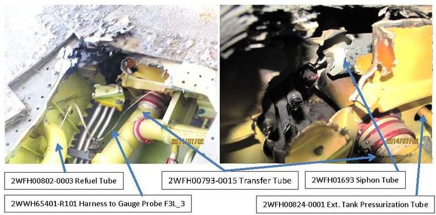
During the mishap, a fuel transfer tube, refuel tube and fuel siphon tube located over the engine
in a fuel tank (Fig-9) were all partially or completely severed by the R3 integral arm ejection
(Fig-10) (Tab J-152). During engine operation, the fuel transfer tube is pressurized. After being
partially severed, this tube leaked a significant amount of pressurized fuel feeding the subsequent
external and internal fires (Tabs J-7, J-8, J-62 thru 68).
Part numbers are exempt from disclosure under FOIA (b)(4)
Fig-10. Fuel system damage (Tab J-68)
(4) Electrical System
Ten seconds after the initial engine stall, the Inverter/Converter/Controller (ICC) number 2 failed
due to a system ground fault indication caused by damage from the R3 integral arm ejection (Tab
F-35A, T/N 10-5015, 23 June 2014
12J-72). The loss of ICC 2 resulted in less than normal electrical power to the aircraft and a loss of
some non-critical functions.
(5) Airframe Structure and Skin
Fig-11. Hole in top of aircraft (Tab S-5)
A hole (10 x 7 inches) in Panel 3331 (top of fuselage) directly above and corresponding to the
hole in the engine fan case was discovered post mishap with the composite plies/fibers splayed
outward (Fig-11) (Tabs J-7 thru J-8). This panel covers parts of the fuel tank that was damaged
and another fuel tank (Tab J-7). Three hydraulic lines and four fuel tubes (discussed in
paragraph 6.a.(3) above) were damaged or severed at this location (Tabs J-61, J-68).
In summary, most outer surfaces of the aircraft skin and panels aft of the air refueling door were
damaged by the fire while the interior bays covered by these panels exhibited a layer of soot with
minimal or no damage (Tabs J-5 thru J-9, S-2). The interior of the engine bay also exhibited
scorching and some metal deformation due to intense heat (Tabs J-14, J-15).
b. Evaluation and Analysis
Initial borescopic examination and limited disassembly of the ME for visual inspection of the fan
was conducted at P&W’s Eglin AFB facility in FL. Subsequent full teardown and analysis of the
ME was conducted at P&W’s West Palm Beach, FL facility, with additional materials laboratory
and analytical support provided by personnel at P&W’s East Hartford, CT facility and the Air
Force Research Laboratory (AFRL) facility at Wright-Patterson AFB, OH (Tab J-147).
(1) Analysis 1 – Engine R3 Failure
Engineering analysis by P&W and the JPO indicates that during the MA’s takeoff roll at 0910L,
the R3 forward integral arm catastrophically failed and liberated from the engine (Tab J-147).
This failure immediately caused an engine stall as the MP began to rotate for takeoff (Tab J-
148). The liberated pieces of the R3 forward integral arm subsequently punctured the engine fan
case and ejected out of the top of the aircraft falling just north of the runway while the aircraft
continued to roll down the runway and eventually stopped (Fig-12, Fig-13). Following the
F-35A, T/N 10-5015, 23 June 2014
13aircraft mishap, a sweep of the airfield located several pieces of this debris (Tabs R-2, R-4).
Simulation by the AIB in an F-35 simulator and review of the CSMU data timeline show the
location of the recovered debris coincident with the time of R3 failure (Tabs S-4.1, DD-3, J-81).
The debris found post-mishap was identified as portions of the R3 IBR forward integral arm and
composite debris (Tab J-151).
Direction of aircraft
Fig-12. Location of debris along runway (Tab S-9)
Fig-13. Fragment of R3 forward integral arm (Tab S-3)
Engineering analysis by P&W demonstrated that the R3 forward integral arm fractured initially
in an axial direction between the second and third stage rotors (forward-aft direction). The
forward integral arm also fractured circumferentially between the forward and aft plate seals and
between the aft plate seal and the R3 disk. These fractures produced two elongated fragments
F-35A, T/N 10-5015, 23 June 2014
14measuring roughly 5-6 feet in length and numerous smaller fragments (Tab J-98, J-100, J-151
thru J-152).
Exempt from disclosure under FOIA (b) (4)
Fig-14. Two main pieces of R3 forward integral arm found along runway
(Tab J-98 and J-152)
Exempt from disclosure under FOIA (b) (4)
FWD
Fig-15. Undamaged example of R3 Forward Integral Arm (Tab J-97)
F-35A, T/N 10-5015, 23 June 2014
15Based on the P&W engineering analysis, the cause of the fracture in the R3 forward integral arm
was determined to be due to High Cycle Fatigue (HCF) progression following a hard tip rub
event (Tab J-92). HCF progression describes the weakening of the R3 forward integral arm after
repeated loads were imparted during continued engine operations after the initial hard rub event.
The hard tip rub event occurred where the R3 plate seals contacted the foam rub strips along S2
(Fig-16) (Tab J-93).
Exempt from disclosure under FOIA (b)(4)
Fig-16. Plate seal and rub strip diagram (Tab J-96)
Analysis of the ejected forward integral arm fragments demonstrated evidence of a hard tip rub,
which resulted in a brief occurrence of extremely high temperatures (Tab J-122). This event
occurred at an undetermined time prior to the mishap; however, no evidence indicates that the
engine or aircraft had been operated outside of the designed flight envelope (the operating
parameters and capabilities of the aircraft) (Tab DD-7).
Evidence of the hard tip rub and subsequent extreme temperature included heat tinting, metal
smearing and heat check cracking adjacent to the primary axial fracture location on the R3 aft
(rear) plate seal (Tabs J-92 and J-166).
F-35A, T/N 10-5015, 23 June 2014
16Fig-17. Heat Tinting, Metal Smearing, Micro-Cracks in Aft Plate Seal (Tab J-106)
This heat damage from the hard tip rub induced a structural change in the composition of the
microstructure and caused cracks to form in the R3 plate seal (Fig-17 thru Fig-20) (Tabs J-106,
J-123). This heat damage can be seen in Fig-18 by the difference in color and texture.
Measurement is
Measurement is exempt
exempt under
under FOIA (b)(4)
FOIA (b)(4)
Fig-18. Aft plate seal adjacent to fracture showing heat damage (Tab J-119)
F-35A, T/N 10-5015, 23 June 2014
17Measurement is
Measurement is
exempt under
exempt under
FOIA (b)(4)
FOIA (b)(4)
Fig-19. Aft Plate Seal 180 degrees from fracture location (Tab J-131)
Micro-cracks formed on the aft plate seal of the R3 and extended radially further into the seal.
These micro-cracks along the R3 plate seal eventually weakened the metal enough to allow a
large axial fracture to develop, which became structurally unstable and led to the catastrophic
material failure (Fig-20) (Tab J-93).
Fig-20. Radial cracks in heat affected microstructure extending .018 inch radially
(Tab J-123)
The extent of the heat tint pattern on both the forward and aft plate seals is depicted in Fig-21.
The location of the eventual catastrophic fracture is depicted as the red line on top of the blue
shaded heat tint area.
F-35A, T/N 10-5015, 23 June 2014
18Fig-21. Total extent of heat tint damage (Tab J-139)
Once the plate seals of the R3 were damaged by the hard tip rub event and subsequent heating,
the micro-cracks began to expand into a larger fracture eventually leading to the ejection of the
entire forward integral arm out of the aircraft (Fig-22) (Tabs J-92 thru J-93).
Fig-22. Fracture Sequence (Tab J-104)
In summary, P&W’s analysis concluded that a hard rub interaction between the R3 plate seals
and the S2 rub strips produced extreme heat that damaged the structure of the seals. This heat
damage resulted in multiple micro-cracks of the aft plate seal which eventually led to a
catastrophic fracture. The fracture produced two main projectiles which punctured the fan case
F-35A, T/N 10-5015, 23 June 2014
19and upper fuselage of the aircraft severing fuel and hydraulic lines. This led to the mishap
aircraft’s engine stall and subsequent fire. (Tabs J-92 thru 94, J-147).
(2) Analysis 2 – Fire
An exterior fire on the MA during takeoff roll was reported by multiple witnesses of the event
(Tabs R-4, R-6, V-1.4). Aircraft sensors detected this fire during takeoff and was verified by
extensive damage to the interior and exterior of the aircraft post-mishap (Tabs J-4 thru J-9).
Fig-23. Fire damage post mishap (Tab S-2)
Based on the evidence and their analysis, P&W and the JPO concluded that the initial fire started
when the R3 forward integral arm fragments were liberated and punctured the engine fan case.
These fragments traveled through a fuel tank severing multiple pressurized hydraulic lines and
fuel tubes. These pressurized fluids then rapidly atomized as they exited the aircraft into the
airstream. The catastrophic engine failure due to the R3 failure provided an ignition source for
the fuel that was no longer contained within the fuel system. The fire, fueled by pressurized
hydraulic fluid and JP-8, burned on the dorsal side of the aircraft fuselage, aft of the aerial
refueling door (Tabs J-7 thru J-9).
After the MP brought the MA to a stop on the runway and shut down the engine, pressurization
to the fuel and hydraulics stopped as designed per JTD (Tab O-2). Photographic evidence shows
the fire continued underneath the aircraft, fed by leaking fuel (Fig-24). At 09:13:55L, aircraft
fire detectors reported a fire in the engine bay, likely due to the auto-ignition of leaking fuel in
the engine bay from the heat of the ground fire. The Fire Chief reported the fire under control 7
minutes and 22 seconds after the initial engine stall was recorded on the MA CSMU (Tab J-5).
F-35A, T/N 10-5015, 23 June 2014
20Fig-24. Ground fire post aircraft shutdown (Tab S-3)
7. WEATHER
a. Forecast Weather
The weather forecast predicted scattered clouds at 4000’, broken clouds at 12000’, winds 220
degrees at 12 knots and visibility of 4 statute miles (Tab F-2).
b. Observed Weather
An observation taken at 0855L reported few clouds at 2500’, scattered clouds at 16000’ and
broken clouds at 25000’. Winds were recorded at 010 degrees at 4 knots. The temperature was
27 degrees Celsius (80 degrees Fahrenheit) and the runway was dry (Tab F-6).
c. Space Environment
Not applicable.
d. Operations
There is no evidence to suggest that weather was a factor in this mishap.
8. CREW QUALIFICATIONS
a. Mishap Pilot
The MP was a current and qualified F-35A Instructor Pilot with a current Form 8 flying
evaluation (certificate of aircrew qualification) dated 9 April 2014 (Tab G-18). The MP was
current and qualified in all aspects of the planned mission (Tabs G-12, G16). The MP was
classified as Basic Mission Capable (BMC) based on sortie look back (Tab G-21). BMC is a
term used to identify the proficiency of aircrew based on the number of sorties and training they
have received in a given timeframe.
F-35A, T/N 10-5015, 23 June 2014
21The MP had a total of 984.5 flight hours at the time of the mishap, of which 33.8 hours was in
the F-35A (Tab G-5). The MP had a total of 113.6 hours as an Instructor Pilot in the F-16 and
8.1 hours as an Instructor Pilot in the F-35A.
Recent flight time is as follows (Tab G-6):
Hours Sorties
Last 30 Days 15.1 11
Last 60 Days 19.7 14
Last 90 Days 28.6 21
9. MEDICAL
a. Qualifications
The MP was medically qualified for flying duties at the time of the mishap. The MP’s most
recent annual military Periodic Health Assessment (PHA) was performed on 12 December 2013.
The MP’s annual dental examination was performed on 15 November 2013. The medical
records contained a current Air Force Form 1042, Medical Recommendation for Flying or
Special Operational Duty, dated 12 December 2013. Review of the Aeromedical Information
Management Waiver Tracking System (AIMWTS) database, a computer system for tracking
aircrew medical waivers, showed the MP did not have a medical waiver at the time of the mishap
(Tab X-3). There is no evidence to suggest that the MP’s physical and medical qualifications
were factors in this mishap.
b. Health
The AIB Medical Member reviewed the medical and dental records in addition to the 72-
hour/14-day histories of the MP. The MP’s records reflected good health and no recent
performance-limiting illness prior to this mishap (Tab X-3). The MP successfully ground
egressed from the MA. There were no injuries associated with this egress. (Tabs V-2.6, X-3).
There is no evidence to suggest the MP’s health was a factor in this mishap.
c. Toxicology
Immediately following the mishap and in accordance with safety investigation protocols, blood
and urine samples were collected on the MP and relevant maintenance personnel and submitted
to the Armed Forces Medical Examiner System at Dover AFB for toxicological analysis. Blood
samples tested negative for ethanol and carbon monoxide levels. Urine drug screen testing was
negative for amphetamine, barbiturates, benzodiazepines, cannabinoids, cocaine, opiates, and
phencyclidine by immunoassay or chromatography. (Tabs X-3 and X-5).
d. Lifestyle
MP testimony, 14-day/72-hour histories and the medical chart of the MP revealed no lifestyle
factors relevant to the mishap (Tabs V-2.6 thru 2.7, X-3).
F-35A, T/N 10-5015, 23 June 2014
22e. Crew Rest and Crew Duty Time
Air Force Instruction (AFI) 11-202, Volume 3, AETC Supplement, General Flight Rules, dated
20 September 2012, prescribes mandatory crew rest and maximum Flight Duty Periods for all
personnel who operate USAF aircraft (Tab O-2). Based upon witness testimony and
supplemental history, crew rest was in accordance with paragraph 9.8 of AFI 11-202, Volume 3
(Tabs V-2.7, X-3). There is no evidence to suggest crew rest was a factor in this mishap.
10. OPERATIONS AND SUPERVISION
a. Operations
The operations tempo of the 58 FS was average to low based on a comparison with a comparable
F-16 Formal Training Unit squadron. The primary mission of the 58 FS is to train new F-35A
pilots. Availability of aircraft, number of students in the pipeline, complexity of mission sets,
and the frequency of Temporary Duty (TDY) and deployments all affect operations tempo (Tab
DD-5).
Due to the fact that the F-35A production and developmental test phases are being conducted
simultaneously, there are multiple restrictions on the F-35A flight envelope (the operating
parameters and capabilities of the aircraft) that reduce the number of mission types to which the
squadron trains currently. There are limited short-duration TDYs for some personnel, and no
deployments for the aviators. These items all reduce complexity for the pilots and reduce
operations tempo (Tab DD-5).
The squadron’s instructors are all previously experienced Instructor Pilots in their previous
fighter aircraft; however, the level of experience in the F-35A for most is very low due to their
recent transition to the aircraft. Due to extended groundings, low aircraft utilization rates and
software immaturity, the squadron has not been able to accrue significant hours or experience
(Tab DD-5). However, there is no evidence to suggest operations tempo was a factor in this
mishap.
b. Supervision
The supervision for daily flying operations comes primarily from the Operations Supervisor, a
daily duty manned by senior pilots in the squadron who brief all pilots before they fly. The
Operations Supervisor is available to assist in the event of malfunctions and generally is the
authority for immediate operational decisions. The Director of Operations is involved in
squadron supervision by approving the daily flying schedule, monitoring student syllabus
progression and accomplishing formal flying and simulator evaluations of the squadron
instructors and students (Tab DD-5). There is no evidence to suggest the level of supervision
was a factor in this mishap.
11. HUMAN FACTORS
The Board evaluated human factors relevant to the mishap using the analysis and classification
system model established by the Department of Defense (DoD) Human Factors Analysis and
F-35A, T/N 10-5015, 23 June 2014
23Classification System (HFACS) guide, implemented by AFI 91-204, Safety Investigations
Reports, dated 12 February 2014 (corrective actions applied on 10 April 2014) (Tab BB-3).
There is no evidence to suggest that human factors were an issue in this mishap.
12. GOVERNING DIRECTIVES AND PUBLICATIONS
a. Publically Available Directives and Publications Relevant to the Mishap
(1) AFI 11-202V3, AETC Supplement, Flying Operations General Flight Rules, 10
January 2012
(2) AFI 11-2F-35V3, AETC Supplement, F-35A Operations Procedures, 2 January
2013
(3) AFI 11-401, Aviation Management, 9 January 2013
(4) AFI 11-418, AETC Supplement, Operations Supervision, 20 May 2014
(5) AFI 13-201, Space, Missile, Command and Control Airspace Management, 21
August 2012
(6) AFI 13-204, Airfield Operations Career Field Development, 9 May 2013
(7) AFI 21-101, Aircraft and Equipment Maintenance Management,
(8) AFI 21-101, Eglin AFB Supplement, Aircraft and Equipment Maintenance
Management, 20 July 2011
(9) DODI 6055.06, Fire and Emergency Services Program, 21 December 2006
(10) EGLINAFBI 11-201, Air Operations, 1 May 2013
NOTICE: All directives and publications listed above are available digitally on the Air Force
Departmental Publishing Office website at: http://www.e-publishing.af.mil or the Official
Department of Defense Website: http://www.dtic.mil/whs/directives/index.html.
b. Other Directives and Publications Relevant to the Mishap
(1) T.O. 00-20-1, Aerospace Equipment Maintenance Inspection, Documentation,
Policies and Procedures
(2) T.O. 00-35D-54, USAF Deficiency Reporting, Investigating and Resolution
(3) T.O. 1-1-300, Maintenance Operational Checks and Check Flights
(4) T.O. 42B-1-1, Technical Manual Quality Control of Fuels and Lubricants
(5) 58 FS F-35, Standards 58 FS Operations Standards
(6) F-35A-FCL-001 F-35A, Pilots Checklist (-1CL Equivalent), Dated 21 August 2013,
Change 4.1
(7) F-35A JTD, Joint Tech Data (Maintenance Tech Data Equivalent) Issue: 20 June
2014
(8) F-35A FSD, Flight Series Data (-1 Equivalent) Issue: 3 June 2014
(9) ALIS-CMMS, Aircraft Maintenance Data
(10) EAFB PLAN 91-204, Eglin AFB, Mishap Response Plan
(11) T.O. 42B-1-1, Quality Control of Fuels and Lubricants
(12) T.O. 42B2-1-3, Fluids for Hydraulic Equipment
(13) JSF AEI 2ZUA28013, Rev A, Fuel Tank Draining
(14) ALIS-SHM, Aircraft Maintenance Data
F-35A, T/N 10-5015, 23 June 2014
24Exempt by FOIA (b)(6)
STATEMENT OF OPINION

                                     F-35A, T/N 10-5015
                              EGLIN AIR FORCE BASE, FLORIDA
                                        23 JUNE 2014

Under 10 U.S.C. § 2254(d) the opinion of the accident investigator as to the cause of, or the factors
contributing to, the accident set forth in the accident investigation report, if any, may not be considered
as evidence in any civil or criminal proceeding arising from the accident, nor may such information be
considered an admission of liability of the United States or by any person referred to in those conclusions
or statements.

1. OPINION SUMMARY

On 23 June 2014, at approximately 0910 hours local time, the mishap aircraft (MA), an F-35A,
tail number 10-5015, assigned to the 58th Fighter Squadron, 33d Fighter Wing, Eglin Air Force
Base (AFB), experienced an engine stall and subsequent fire during takeoff roll. The Mishap
Pilot (MP) aborted the takeoff, stopped on the runway and safely egressed the still burning
aircraft. Emergency crews responded and extinguished the fire. There was no damage to private
property and minor airfield damage. The MA engine sustained significant damage and the aft
(rear) two thirds of the MA sustained significant fire damage. Total mishap damage costs were
estimated to be in excess of $50,000,000.00.

I find by clear and convincing evidence that the cause of the mishap was a material failure of the
third stage Integrally Bladed Rotor forward integral arm. Pieces of this rotor arm ejected through
the upper portion of the aircraft fuselage, which severed internal fuel and hydraulic lines. The
fuel and hydraulic fluid ignited and the ensuing fire encompassed the aircraft around the area
where the fuselage was penetrated and aft as the MP correctly aborted the takeoff. The MP
performed an engine shut down and egressed while the leaking fluids continued to burn on and
around the aircraft. The fire was extinguished approximately seven minutes after the initial
indications of a fire.

I developed my opinion by analyzing factual data from historical records, engineering analysis,
witness testimony, flight data, flight simulations, animated simulations, information provided by
technical experts, Air Force directives and Technical Orders.

2. CAUSE

The mishap was caused when the third stage rotor (R3) of the fan module fractured. This
fracture occurred on the R3 forward integral arm and was caused by High Cycle Fatigue
following a hard tip rub event on the aft plate seal of the integral arm. The aft plate seal
experienced heat damage from a hard tip rub against a strip of foam material attached to the
second stage stator. Evidence of this hard tip rub was observed on the recovered segments of the

                                    F-35A, T/N 10-5015, 23 June 2014
                                                    26
You can also read