Computer Sand Art - CAD Journal
←
→
Page content transcription
If your browser does not render page correctly, please read the page content below
1

                                       Computer Sand Art
                           Erkan Gunpinar1     , Sagit Asman2 and Gershon Elber3

                              Istanbul Technical University, gunpinar@itu.edu.tr
                               1
                       2
                        Technion, Israel Institute of Technology, sagit@cs.technion.ac.il
                     3
                       Technion, Israel Institute of Technology, gershon@cs.technion.ac.il

                           Corresponding author: Erkan Gunpinar, gunpinar@itu.edu.tr

         Abstract. Intuitive interactive methods for novice users to create 3D content and 3D geom-
         etry have eluded the CAGD community for several decades, and they continue to be critical
         yet unresolved challenges. The need for such methods is even more acute considering the
         fact that 3D printing is becoming a commodity. In contrast, modern geometric modeling
         tools are very complex and continue to be used primarily by professionals such as architects
         and engineers.
             Part of the difficulty of novice users to create 3D content might be found in the fact that
         input/output devices are mostly 2D. While novice users, in real life, do interact daily in 3D
         environments, typically, they do not create 3D content. In this work, we combine a Leap
         Motion device [42] / mouse+keyboard with the intuitive notion of sand art, or the creation
         of 3D artifacts on the seashore, using droplets of wet sand. The result is a very simple, yet
         highly interactive 3D modeling interface that is also demonstrated on several applications.

         Keywords: Leap Motion, sketch based design, geometric modeling, 3D content creation
         DOI: https://doi.org/10.14733/cadaps.2021.1-23

1   INTRODUCTION AND FUTURE WORK
The creation of a 3D geometric modeling (GM) environment for novice users has been a challenging goal in
the computer aided geometric design (CAGD) community, almost since the inception of the field. One of the
very first GM interactive systems was Sketchpad [46], emphasizing the importance of an intuitive geometric
design system. Yet, half a century later, we still strive for 3D content creation abilities for novice users. This
fact is even more overwhelming considering the fact that the same novice users are getting to a point in time
where they are able to produce and print 3D content at home, using additive manufacturing technologies.
    Hence, it is not surprising that the problem of GM for novice users (GMun ) has captured the attention of
many researchers over the years, but unfortunately so far with a limited success. While part of the difficulty
can be attributed to the fact that input and output devices are still mostly 2D (i.e. a computer mouse and
a screen), content creation in 3D for non specialists turned out to be far more difficult than could have been

                                                    Computer-Aided Design & Applications, 18(1), 2021, 1-23
                                               ©   2021 CAD Solutions, LLC, http://www.cad-journal.net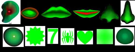
2

  (a)        (b)          (c)                (d)                  (e)            (f)            (g)          (h)
Figure 1: Different masks of droplet (white region), of varying sizes and shapes. Droplets’ mask can not only
be in different sizes ((a) and (b)) but also in arbitrary shapes, like a square (c), text (d), boom (e), heart solid
(f) and wireframe (g), and even a smiley (h).

expected. In the past, quite a few efforts toward GMun were made and in different directions. Restricted GMun
efforts, that allowed only a minimal set of modeling abilities were quite successful, while generality in GM came
at the almost immediate expense of lack of intuitive use. Interestingly enough, the question of user-computer
interaction has been intensively investigated, including in three dimensions, but not necessarily in the context
of GM [37].
    In [29], an effort was made to support the recognition of pen strokes and simple shapes such as arcs, lines,
rectangles, and freeform curves, only to interactively handle surface constructors such as extrusion, ruling and
sweeps and even introduce cuts (holes) through them. A similar modeling approach for polygonal geometry
can be found in [34, 49]. Both approaches are quite general but unfortunately required fairly sophisticated 3D
abilities from their end users.
    Others aimed at providing tools to ease the interactive and intuitive human-computer interface of a GMun
system. In [26], symmetry of planes in 3D was sought to aid interpreting end user’s 2D sketchings as 3D
geometry. Looking at more restricted GM domains, the level of interactive and intuitive GMun behavior that
has been reached is higher. In [47], pottery is simulated, creating and focusing on surfaces of revolution,
using free hands’ gestures, captured using a Leap Motion device [42]. Another quite successful example is the
interpretation of 3D from sketched silhouettes [35]. Later on, [35] was combined with other operations like
cutting and more advanced variations that tried to properly interpret self occluding silhouettes in synthesizing
3D geometry [39]. In [24], a related approach is taken where a 3D curve is inferred from two 2D drawings
of the same curve that are correlated. In [27], a feasibility study on using Leap Motion for shape modeling
in VRML/X3D environments was introduced. In [28], a set of interaction techniques such as rotation, tilting,
twisting, and bending was described for 3D shape modeling. In [20], real-time structural design exploration
was carried out using 3D direct manipulation to improve the structural performance. In [38], a constraint-
based modeling technique for mid-air interaction [25] called 3D touch-and-drag was introduced, which was
an improved version of Artist3D [1] using a Leap Motion device [42] and an Oculus Rift DK2 headset [10].
In [43], a system enabling users to interactively design a 3D object by comparing a graphical model with a real
product was introduced. A system, called FlatFitFab, is presented by McCrea et al. to author planar section
structures to design and fabricate 3D objects [41]. Paczkowski et al. introduced a 3D modeling approach on
a tablet device for creating developable surfaces, inspired by traditional paper crafting [45]. A Kinect-based
interactive system (called BodyAvatar ) was developed by Zhang et al. that allows novice users to create
freeform 3D avatars using body gestures [50]. In [40], a system called SandCanvas was developed to create
sand art pictures. The system involves a multi-touch media for sand art drawing and supports gestures to
manipulate sand. Wong et al. presented an interactive sand art drawing system using one RGB-D sensor to
produce pictures using the sand particles [48]. Sand drawing functions (such as sand erosion, sand spilling and
sand leaking) were supported in line with gestures.
    There are professional tools for 3D CAD modeling (i.e., sculpting) such as Maya [9], Zbrush [11], Unity [17]

                                                        Computer-Aided Design & Applications, 18(1), 2021, 1-23
                                                   ©   2021 CAD Solutions, LLC, http://www.cad-journal.net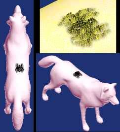
3

and Blender [2]. This work does not aim to replace these modern CAD tools that are for professionals. Not
all novice users (such as high school kids) are able to use these tools. On the other hand, most of these users
will be able to employ the SandArt system presented in this work, drawing upon the very intuitive SandArt
metaphor that is also extended in several ways. These extensions include the creation of 3D content using
a-priori designed general masks, and the support of varying levels for both (colored) protrusions and extrusions
on a model, using a single gesture.
     A successful GMun effort must draw upon the intuition of the novice user. In this sense, Silhouettes are
highly depicting and simple. Similarly, pottery is a physical process that is familiar for many. Interestingly
enough, both the Silhouettes’ based approach and the pottery simulation draw upon two dimensional curve
sketching: the silhouette’s curve and/or the section curve of the surface-of-revolution. It is possible that the
ease-of-use in these two cases stems from, essentially, only handle curves.
     The concept of sand art is introduced for novice users toward the creation of geometric content using
intuitive modeling concepts. A SandArt mask enables the end users to create both protrusions and extrusions
over a model using a single gesture, which makes SandArt simple and easy to use. This work is also aiming
at a restricted GM domain, and draw upon the very intuitive notion of sand art, where droplets of wet sand
are used to accumulatively build arbitrary 3D sand structures. Like many recent similar efforts, we also use a
Leap Motion device [42] to capture hand positions as well as rely on hand gestures to hint on the state we are
in, like idle or undo states.
     The rest of this paper is organized as follows. In Section 2, a simple SandArt simulation environment
is described that is capable of handling explicit functions or height fields. Section 3 extends this explicit
SandArt to the SandArt3D environment that supports general 3D geometry. In Section 4, possible geometric
applications of SandArt are introduced. Furthermore, 3D contents designed using SandArt3D are shown as
part of a simple user study. Finally, concluding remarks and opportunities for future work are presented in
Section 5.

2   THE SandArt ENVIRONMENT
The notion of SandArt is highly intuitive. Every kid, being on the seashore, has experienced grabbing a handful
of wet sand and letting it drip, only to create some 3D sand structures from these sand droplets.
    People enjoy playing with sand [22], which is pleasant to touch, helps to relax and eliminates the fear of
failure [13]. Sand is open-ended and well-suited to the explorative and imaginative nature of human, particularly
young children [5]. Sand play is a creative modeling ("hands on") approach, there are no preconceived ideas
about art in sand and there is a wonderful freedom using sand creatively [21]. The activity of designing
something or creating a content in human’s mind has a similar nature like sand playing as it is explorative and
open-ended. In SandArt, there is no fear of failure as sand droplets can be either added or removed and the
user can undo or redo similar to sand playing. An intuitive concept of "sand art" is used in the present work
as a human computer interaction interface and can help minimizing the barrier between the human’s mental
model of what they want to accomplish and the computer’s understanding of the user’s task, which is a long
term goal of HCI systems [8].
    In this section, we adapt this metaphor of SandArt into a very simple, non-physically based, geometric
modeling system that can construct any shape in the form of an explicit function, F. Much like real-life
droplet based sand art that has no over-hanging geometry or geometry with negative slopes, we similarly allow
here a modeling construction that is always explicit: every XY position has exactly one Z location below or
above it.
    Consider a 2D grid, G, of size n × m. Every entry in the grid designates a height that approximates the
value of F in that neighborhood. In other words, G defines a (discrete) height field that approximates F.
Given G, a piecewise linear approximation of the explicit function F can be created, by simply approximating
every four adjacent values in G, gi,j , gi+1,j , gi,j+1 , and gi+1,j+1 , 0 ≤ i < n − 1, 0 ≤ j < m − 1, by two

                                                    Computer-Aided Design & Applications, 18(1), 2021, 1-23
                                               ©   2021 CAD Solutions, LLC, http://www.cad-journal.net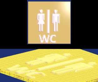
4

triangles ∆(gi,j , gi+1,j , gi+1,j+1 ) and ∆(gi,j , gi+1,j+1 , gi,j+1 ).
    Having G, we also need to handle the droplets that affect it. Real-life sand droplets typically deposit
a shape similar to a Gaussian once they are dropped. Consider a second 2D grid, M, of size p × q. M
can be encoded with the Gaussian function values so that at ( p2 , 2q ) it achieves its maximum value while it
(almost) vanishes to zero on the boundary of M. See Figure 1 (a) and (b). M is denoted the droplet’s mask.
Now, let T(x,y) (M) denote the translation of mask M so M( p2 , 2q ) is located at (x, y). Then, the process of
dropping one sand droplet at location (x, y) on G amounts to adding the values of the translated droplet’s
mask, T(x,y) (M), to G (up to some vertical scale, s):

                                    p        q
                                G x − + i, y − + j + = sM(i, j),
                                     2        2
                                                0 ≤ i < p, 0 ≤ j < q.                                          (1)

    Finally, note that a single droplet is usually small and has a local effect. I.e, typically p, q
5
(a) (b) (c)
Figure 2: Users’ supported gesture: (a) horizontal Open hand, (b) vertical thumb up Open hand, (c) vertical
thumb down Open hand.
Figure 3: SandArt droplets can come in any shape and any color as can be seen in this figure. A droplet is
merely a mask based on an image. Using the masks shown in Figure 1 (b), (d), (e), and (f). Also note the
fist hand on the top right and the vertical line below the fist to guide the end user to the exact location the
drops will go to.
4. Control over the color of the droplets. Clearly, we can paint individual polygons or vertices in different
colors and hence can support colorful droplets. See Figure 3.
5. In our virtual SandArt, one can not only deposit material but also remove it. In other words, the user
can toggle between adding or subtracting material which merely means adding or subtracting mask M
to/from G. See Figure 4.
The SandArt environment is very simple and intuitive while it also has one major limitation: it can only
handle explicit surfaces. In the next section, we will show how this limitation can be mitigated with virtually
no affect on the interactivity and ease of use.
Computer-Aided Design & Applications, 18(1), 2021, 1-23
© 2021 CAD Solutions, LLC, http://www.cad-journal.net6
Figure 4: Droplets can be either added or subtracted from the current geometry. Herein, the pink color hill
was created by adding material, only to subtract the blue zone, creating a volcano-like scene.
3 THE SANDART3D ENVIRONMENT
SandArt3D is extending SandArt by allowing the application of droplets from any direction. Hence, it can
be used to build general closed 2-manifold geometries. We will start with the basic ideas, only to discuss
mirroring abilities in Section 3.1, present some extensions to the basic masks in Section 3.2, and briefly discuss
additional functionality in Section 3.3.
SandArt3D is initialized with a 3D triangular mesh model T rather than using a 2D explicit grid. Unlike
SandArt, SandArt3D allows the end user to apply droplets from any direction. T can be refined to achieve a
target triangle’s maximal edge length, controlling the smoothness of the result.
Like SandArt, SandArt3D continues to apply droplets from the +Z direction. However, the user can rotate
T to any desired orientation. Once oriented, T is then decomposed into:
• Static triangles, P s : triangles that are not going to be directly affected by droplets in this orientation
unless their vertices are shared by any dynamic triangle. This includes all down facing triangles and/or
triangles that are, at least partially, hidden from above.
• Dynamic triangles, P d : fully visible triangles from and facing +Z that can be affected by droplets.
In other words, and for efficiency reasons, we have isolated the set of triangles that can be affected by the
droplets, in a process similar to back face culling, in computer graphics [31].
To further speed up the processing of P d , a Bounding Volume Hierarchy for the dynamic triangles is now
built in 2D (similar to that of [32]) that is called Bounding Rectangle Hierarchy (BRH). As a shape of a box,
axis-aligned, tight-fitting rectangle is utilized. To build BRH, a top-down method is employed, which begins
with the polygons in P d and recursively subdivides bounding rectangle along its longest axis into two equal
areas until all leaf nodes are indivisible.
As in SandArt, the user can select an image mask, M, of the desired shape, and a color, only to be
ready to apply droplets. The same gestures used by SandArt are employed here as well - droplets are dripped
using the closed fist hand gesture. Then, if the user desires dripping droplets from any other direction, T is
reoriented, and the above initialization processes are carried out again. Algorithm 1 outlines the entire Sand
Art 3D interactions. In Line 13, and if so requested in Line 12 in Algorithm 1, we repeat the initialization
of the mesh toward dripping droplets from a different direction. Because elongated polygons might enter the
mesh a dripping location, a refinement of the mesh is also reapplied (in Line 2).
When a mask of a droplet is applied over T , a naive search to find the affected dynamic polygons can be
computationally expensive if the number of polygons in P d is high, and is linear in the number of polygons in
P d . To alleviate this difficulty, and striving for a sub-linear complexity, the BRH is employed, comparing the
XY rectangle dimensions of M against the BRH.
Computer-Aided Design & Applications, 18(1), 2021, 1-23
© 2021 CAD Solutions, LLC, http://www.cad-journal.net7
Algorithm 1 Overview of the SandArt3D interactions.
1: Load a 3D triangular mesh T ;
2: Remesh T to make it isotropic and uniform;
3: Transform T to the desired orientation;
4: Decompose T into static and dynamic triangles;
5: Build an XY bounding rectangle hierarchy for the dynamic polygons;
6: Select a mask shape and mask color;
7: Position a horizontal open hand at the desired location above T ;
8: while dripping droplets using closed fist gesture do
9: Update locations of vertices in the dynamic polygons, which are affected by the droplet’s mask;
10: Display the updated T model;
11: end while
12: if droplet dripping on T from a different direction is required then
13: Go to line 2;
14: end if
To effectively find the polygons among the vertices in P d that are affected by mask M positioned at
(x, y), denoted T
(x,y) (M), a bounding rectangle for T(x,y) (M), as B (T(x,y) (M) , is first computed.
B T(x,y) (M) is then intersected with the BRH tree elements. A BRH branch with no intersection with
B T(x,y) (M) can be immediately ignored. Leaf branches of the BRH that are reached by this recursive
search, contain dynamic polygons that may be require an update. Consider some vertex, v, in a dynamic
polygon, v = (vx , vy , vz ). vz of v is updated as follows:
∆vz = sT(x,y) (M) (vx , vy ),
= s (M) (vx − x, vy − y), (2)
where s is a vertical scale control, and vz = vz + ∆vz .
Finally, vertices on shared edges between static triangles and dynamic triangles are also updated in the
static triangles, to follow their dynamic neighboring vertices, making sure the model remains watertight.
3.1 Mirroring Droplets
Symmetries in geometry occur in many natural and man-made objects, and hence its support can be useful in
any GMun systems. Herein, we have added plane-mirroring ability for SandArt3D. When the user adds/removes
droplets from one side of a mirroring plane, droplets modify the geometry at the reflected side as well. The
mirroring plane is always vertical such that it contains the Z axis. Figure 5 presents the different steps in using
the plane-mirroring ability in SandArt3D. A mirroring plane is first activated and positioned (i.e., Figures 5 (a)).
Then, when the closed fist hand gesture is applied, the droplets also drip in the reflected side of the plane
(Figure 5 (b)). Finally, the object obtainedhas symmetrical parts shown in green (Figure 5 (c)).
The bounding rectangle B T(x,y) (M) of some translated mask T(x,y) (M) is computed and mirrored
across the mirroring plane. This mirrored rectangle is now recursively intersected against the BRH to isolate
the dynamic triangles in the affected mirrored zone. Finally, the vertices of these affected triangles are reflected
back to the original bounding rectangle, through the mirroring plane, only to compute their elevation update
in Z, following Equation (2).
Computer-Aided Design & Applications, 18(1), 2021, 1-23
© 2021 CAD Solutions, LLC, http://www.cad-journal.net8
(a) (b) (c)
Figure 5: (a) A mirror plane (in purple) is activated and positioned at the center of an object (in orange).
(b) The droplets start dripping and the reflected side across the plane is also affected by the droplets. (c) The
object finally obtained has symmetrical parts in green, with respect to the mirroring plane (in yellow), viewed
from above.
3.2 SandArt3D Masks
In the SandArt case, we experimented with masks that were completely positive, while we allowed one to either
add or subtract the whole mask. Herein, we experimented with a different, signed, masks, striving for some
intuition while also allowing for simple synthesis and visualization of these masks, as images. The use of signed
gray levels in the full RGB can provide a very high precision that is not really necessary in the SandArt (3D)
task. Hence, herein we chose to assign one color channel (green) to positive mask values and one color (red)
to negative ones. Consider a new type of colored mask, M3D , and let ri,j and gi,j represent, respectively, the
red and green levels at location (i, j) of M3D . Assuming RGB values of zero to 255, the (i, j) value of mask
M3D (i, j) is set as:
gi,j − ri,j
3D
M (i, j) = . (3)
255.0
A fully green mask location has a value of 1.0, while a fully red mask location will result in a value of −1.0.
While noting that this color assignment is not unique (i.e. M3D (i, j) = 0.0 for all cases for which gi,j = ri,j ),
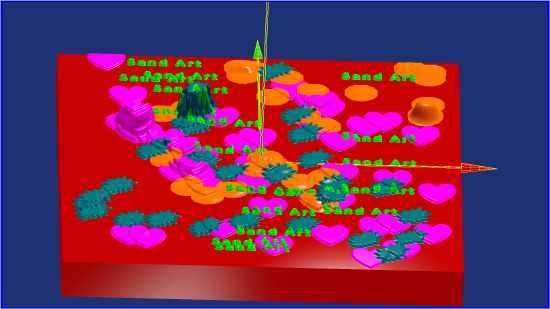
this assignment also allows us to have signed mask that are intuitive to view and edit, as images. See Figure 6
for an example, showing the creation of an ear mask. The helix part of the ear is encoded with green colors as it
should be raised by the droplets. While the parts of the external auditory canal are reddish as they should create
a depression when the droplet’s mask is applied. Such masks can be created with common image processing
tools. For example, one can start with outline curves. Then, colors are assigned to the curves, possibly with
color gradients along the curve. Finally, color gradients can also be applied (interpolated) between the curves,
filling the image mask.
3.2.1 Masks for Texts and Characters
One potential source for curves conversion into masks are outline fonts. Outline fonts are piecewise quadratic
or cubic close Bézier curves [3], possibly with holes (that are also closed piecewise Bézier curves). All modern
operating systems and type-setting software employ outline fonts as they are scalable (unlike raster fonts).
That said, one can extract any text from any outline font, and optionally fill it, optionally with color gradients,
creating the desired (text) mask. Figure 1 (d) is one simple example.
Computer-Aided Design & Applications, 18(1), 2021, 1-23
© 2021 CAD Solutions, LLC, http://www.cad-journal.net9
(a) (b)
Figure 6: SandArt3D mask creation: (a) The colors for the drawn curves are assigned first. The color gradient
is added inside the inner curve. (b) Color blending is carried out between the curves.
3.3 Additional SandArt3D Functions
In modeling sessions, a snapping option of SandArt 3D can be useful from time to time. In some modeling
cases, the user requires to precisely and steadily position his/her hand, which is practically impossible, partially
due to the inaccuracy and noise in the Leap Motion device. The optional location-snapping fixes the droplet’s
position to the initial location, where the closed fist hand gesture is used, and remains steady enough.
In addition, one can either employ the original colors of individual pixels in the mask or employ a whole
new color, globally. Either way, these colors are also transferred to the affected vertices in P d , in addition to
affecting vz .
4 RESULTS AND DISCUSSIONS
In this section, possible applications of SandArt are first introduced, in Section 4.1. 3D contents designed
using SandArt3D are shown and details on the algorithms performance, such as computational time, are given
in Section 4.2. Finally, a small user study with SandArt3D is presented, and its results are discussed, in
Section 4.3.
4.1 Possible Applications for SandArt
All the SandArt examples presented in this section are from interactive sessions using the presented virtual
SandArt, on a Windows machine using Intel i7 3.4Ghz (single core) and an AMD Radeon HD 9700 graphics
card. While the SandArt uses no BRH, it has a simple quadtree division of the grid G into cells that contained
the relevant polygons for these cells in G. This division is tested against the mask, much like the BRH, to
speed up the process. With this division, we were able to achieve real time performance of around 20 frames
per second or more and dozens of droplets per second for grid (G) sizes of up to around 1000 by 1000. Masks
were all less than 100 × 100 in size.
The SandArt approach proposes a very simply yet highly effective and intuitive user interface to create
3D content that is restricted to explicit functions’ form. Nonetheless, we can foresee quite a few dedicated
applications beyond direct modeling and 3D content synthesis. Before we present these applications, we add
an additional feature to the presented system. Every element in the grid G is now going to have upper and
lower height limits. In other words, the droplets will elevate G only until G reaches the upper envelope limit,
and similarly for the lower envelope limit.
Computer-Aided Design & Applications, 18(1), 2021, 1-23
© 2021 CAD Solutions, LLC, http://www.cad-journal.net10
Figure 7: SandArt of a castle. The Z elevation (depth) map of a pre-rendered castle is etched into this model
and serves as an upper envelope limit on the created geometry. An 11 year old kid is in the process of building
the castle. Note the leap motion [42] device below her fist.
Figure 8: SandArt game of Submarines. Ten randomly placed yellow submarines of different sizes are hidden
in the blue ocean, only to be discovered when droplets are falling over these ships.
With this addition, we consider three applications in this section. Section 4.1.1 demonstrates a castle
building using SandArt, Section 4.1.2 demonstrates SandArt in a game of ‘Submarines’, and Section 4.1.3
demonstrates SandArt handling of 3D terrain. In all the presented examples, G is a grid of size 500 × 500.
4.1.1 SandArt Castle Building
Consider a Z-buffer rendering of some castle, from above. Now extract the Z elevation (depth) map [31] of the
result of the rendering and etch this information as an upper envelop limit of G. Anyone working in this limited
SandArt environment will be able, with ease, to raise grid G up to the upper envelope - the castle. Hence,
end users can drop virtual sand droplets until the entire castle is being exposed. See Figure 7. Clearly, any
3D scene can be etched as the lower and/or upper envelope limit of G, creating an application that gradually
exposes any initially hidden structure.
4.1.2 SandArt Submarines
Taking this idea, of an upper envelope limit over G, a step forward, one can etch n 3D submarines at random
places and sizes over G, and let the end user find them by dripping virtual sand droplets as submarines’ detectors
and exposing a ship when the droplet (partially) covers it. In the example of Figure 8, the submarines are
painted in yellow over a blue ocean.
Computer-Aided Design & Applications, 18(1), 2021, 1-23
© 2021 CAD Solutions, LLC, http://www.cad-journal.net11
Figure 9: Terrain discovery using SandArt. The height field of this terrain is registered with the shown map,
only to allow the end user to raise the terrain up to the right elevation. Note the fist over the leap motion
device.
Figure 10: Some of the colored masks used in the SandArt3D modeling sessions.
4.1.3 SandArt Terrain Handling
Another possible related application is terrain processing that is almost always an explicit function. Combined
with texture that is registered and glued to G, in the form of a map (image) of that area, the end user
can get a first hand experience on the elevation of the examined zone, either by aiming to reconstruct the
correct terrain’s height in an unlimited editing mode, only to be compared to the real data terrain map (DTM)
elevation information and ranked according to the differences in elevations, or by using the DTM and the
terrain as the upper envelope limit. See Figure 9.
4.2 Results and Discussion for SandArt3D
All the examples presented in this section are from interactive sessions using SandArt3D, on a laptop with
Windows machining using Intel i7 2.6Ghz (single core) and an Intel HD 4600 graphics card.
Figure 10 shows some of the masks used in the modeling sessions. As an example, there are both red and
green colors in the mask of an eye (Figure 10 (b)) as eyes are spherical protrusions (positive elevation values)
in a larger spherical socket depression (negative elevation values).
We present two possible applications to SandArt3D: adding details/features and text/character etching on
the models as reliefs. Figures 11 and 12 show results from these applications. The initial input models can be
Computer-Aided Design & Applications, 18(1), 2021, 1-23
© 2021 CAD Solutions, LLC, http://www.cad-journal.net12
Table 1: Total model creation times (tS , in minutes) for the models in Figures 11 and 12.
Model tS
Natural scene 9
Virtual planet 6&7
Human face 11 & 10
Unicorn 2
Diamond ring 1
Text/character etching examples13
(a)
(b)
(c)
(d)
(e)
Figure 11: Adding features to the input initial 3D triangular mesh models (on the left, in red): (a) Natural
scene. (b) Virtual planet. (c) Human face. (d) Unicorn. (e) Diamond ring.
4.3 User Study - SandArt3D
A small user study involving ten mechanical engineering students was conducted to design models at their
choosing, using SandArt3D. All students have already used at least one commercial CAD software, while they
are non-professional CAD users. Table 3 includes more information on these users. Two weeks prior to the user
Computer-Aided Design & Applications, 18(1), 2021, 1-23
© 2021 CAD Solutions, LLC, http://www.cad-journal.net14
(a)
(b)
(c) (d)
Figure 12: Text/character etching as reliefs: (a) A man with a t-shirt on which texts are printed. (b) A
wrestler with a tattoo on his breast and a woman with a t-shirt on which a webdings [19] font is printed. (c)
A wolf on which a spider settles. (d) A WC relief on a plate.
study, SandArt3D was presented to the students to make them acquainted with the capabilities of SandArt3D.
They were then asked to determine what they like to design in the modeling session. The users came up with
a design idea and the user study was conducted individually, for each user. The necessary masks were designed
and the input stock model was prepared. A short tutorial, which was at most 20 minutes, was given to all
Computer-Aided Design & Applications, 18(1), 2021, 1-23
© 2021 CAD Solutions, LLC, http://www.cad-journal.net15
Table 2: Computational time, in seconds, for the orientations presented in the respective figures. nP =
Number of polygons in the model, nP d = number of dynamic polygons, tD = processing time for decomposing
the polygons into static and dynamic polygons, tBRH = processing time to build the bounding rectangle
hierarchy.
Model nP nP d tD tBRH
(Sec.) (Sec.)
Man, Figure 12 (a) 20482 9927 0.692 0.02
Horse, Figure 11 (d) 37298 13890 1.948 0.026
Wolf, Figure 12 (c) 20170 7857 0.631 0.016
Crab, Figure 13 (a) 19372 8986 0.593 0.021
UFO, Figure 14 (e) 29520 12980 1.286 0.031
Table 3: User study summary, with times in minutes. tP = Approximate SandArt3D practice time before
starting creating the selected model, tS = total model creation time in minutes, Q1/Q2/Q3: Questions that
the users answered after the modeling session (see text).
User# Age Sex tP tS Q1 Q2 Q3
(min.) (min.)
1 23 M 120 21 2 3 3
2 25 M 60 9 3 3 4
3 23 M 25 5 2 3 3
4 27 M 65 5 2 4 4
5 24 F 20 11 4 3 4
6 24 M 20 4 4 4 4
7 23 F 20 6 4 3 4
8 24 F 30 9 4 4 5
9 23 F 30 3 4 4 4
10 25 F 40 8 5 4 5
users on using SandArt3D. A practice time was then provided to the users to gain some first-hand experience
with SandArt3D. Depending on the design, the practice time changed (see Table 3). Only then, the user
worked on the design he/she desires to create. All user design processes and actions were recorded.
Figures 13 and 14 show the models created by the users using the initial models shown on the left. User
1 generated eyes, hands and foots for a crab starting with an initial model of a body of a crab (See Figure 13
(a)). An animated character with eyes, mouth, ears, nose and hairs was created by User 2 (See Figure 13
(b)). A cake and a Sri-Yantra [15] were generated by Users 3 and 4 (See Figures 13 (c) and (d), resp.). Two
contents with fairy chucks [6] and a roof of a public bath were created by Users 5 and 6 (See Figures 13 (e)
and 14 (a), resp.). A cactus and a high hill with antennas on the top were constructed by Users 7 and 8 (See
Figures 14 (b) and (c), resp.). Finally, a man with six-packs and a UFO were generated by Users 9 and 10
(See Figures 14 (d) and (e), resp.). Times to create these models were mostly less than 10 minutes except
Computer-Aided Design & Applications, 18(1), 2021, 1-23
© 2021 CAD Solutions, LLC, http://www.cad-journal.net16
User 1 (see Table 3). When his recorded design video was watched, we observed that User 1 had difficulties
locating the model at the appropriate position and orientation, for dripping droplets, as the body of the crab
should be rotated and translated many times, to generate its hands and foots.
Following the design session, each user was asked to complete a survey including three questions based
on a Likert scale [23] (1: Strongly Disagree, 2: Disagree, 3: Neutral, 4: Agree, 5: Strongly Agree). These
questions were:
• Q1. SandArt3D is easy to use to generate my content.
• Q2. SandArt3D enables me to create the design I imagine.
• Q3. I would like to use SandArt3D in my future designs.
The last three rows in Table 3 shows the user responses. The users have had mostly positive feedback
about SandArt 3D. The users with negative responses mainly complaint about the inaccurate positioning of
droplets, which is due to the leap motion [42] limitation, not SandArt3D.
We have also used retrospective think-aloud [33], which has been done after the design sessions, as many
users find thinking loud difficult and it makes them feel uncomfortable [44]. After watching the recorded design
videos together with some users, their feelings/thoughts about SandArt3D has been asked. User 1 (generated
crab) stated that he used model transformation many times, which was nontrivial to set the mirroring plane
using the user interface. Inaccurately positioning droplets at the desired locations made him feel uncomfortable.
However, he liked the feeling of adding droplets on a model and had a nice design experience. User 4 (generated
Sri-Yantra) complaint that he could not accurately position the SandArt3D droplets at the desired location.
Thus, he used the undo button several times to erase the droplets on the model. Nevertheless, he said that
he received the sand art intuitiveness while using SandArt3D. User 9 thought that adding pectoral muscles
and six-packs to a human body using a single gesture (i.e., closed fist hand) was impressive. On the other
hand, the function of mirroring droplets in SandArt3D was useful, but she found it difficult to set the mirroring
plane. Therefore, the model transformation interface can be improved and user-friendly.
5 CONCLUSIONS
We have presented a very simple yet effective user interface that allows novice users to synthesize fairly
complex 3D geometry. The geometry can be in a form of an explicit function (SandArt) or a 3D triangulated
mesh (SandArt3D). At every point in time, the interface can be used in a variety of general geometry-related
applications. As a modeling system of 3D geometry, this GMun system is highly intuitive, flexible and simple
to use, and users could start working with it, in minutes. However, the system is also imprecise and it is
difficult to pinpoint droplets.
In SandArt, a 2D grid is employed in which every entry designates a height. When the droplets affect the
grid, the height values of entries that intersect with the SandArt mask are updated. SandArt3D allows the
application of droplets from any direction on a closed 2-manifold geometry. Given a 3D triangular mesh model,
the polygons are decomposed into static and dynamic polygons. Droplets only affect the dynamic triangles,
which are fully visible triangles from and facing +Z direction. Plane-mirroring ability is also developed for
SandArt3D in such a way that droplets also modify the geometry at the reflected side. SandArt3D masks
are two dimensional: green and red levels for positive and negative mask values, resp. Indeed, without a-
priori designed (application-based) SandArt3D masks, it is hard to create complex shapes using our system.
Therefore, a comprehensive database of SandArt3D masks should be built as a future work that will allow
novice users create a variety of non-trivial shapes, much like a bank of images popular in many image editing
tools. Additionally, one might consider expanding on the set of hand gestures for different surface manipulation
operations (such as crease, inflate, grab and pinch), while this might affect the simplicity of the presented
system. Finally, the extension of the functionality of SandArt to enable end users create geometries with
arbitrary Genus from scratch is also desired.
Computer-Aided Design & Applications, 18(1), 2021, 1-23
© 2021 CAD Solutions, LLC, http://www.cad-journal.net17
(a)
(b)
(c)
(d)
(e)
Figure 13: Models created in a user study, from the red initial models on the left: (a) A crab by User 1 ([4]).
(b) An animated character by User 2. (c) A cake by User 3. (d) A Sri-Yantra by User 4 ([16]). (e) Fairy
chucks by User 5 ([7]).
Computer-Aided Design & Applications, 18(1), 2021, 1-23
© 2021 CAD Solutions, LLC, http://www.cad-journal.net18
(a)
(b)
(c)
(d)
(e)
Figure 14: Models created in a user study, from the red initial models on the left: (a) A roof of a public bath
by User 6 ([12]). (b) A cactus by User 7. (c) A high hill with antennas by User 8. (d) A man with six-packs
by User 9. (e) A UFO by User 10.
Computer-Aided Design & Applications, 18(1), 2021, 1-23
© 2021 CAD Solutions, LLC, http://www.cad-journal.net19
Figure 15: A vertical pillar created using a mouse (cyan) and a Leap Motion (green) interface, using the same
mask. Clearly the drift due to the device and the unsupported hand is far significant in the case of the Leap
Motion.
Figure 16: (a, b) Models are generated in a few seconds using SandArt3D with a single mask (on the top or
left) via the mouse+keyboard interface from the (red) initial models (on the left). (c) The castle model was
created using (SandArt3D) sculpting by means of predefined (circular) masks with different sizes, which was
less accurate than the one in (b). (d) A human face created using Sculptris.
We provide a vertical bar that shows where a droplet will be affecting G (I.e. see below the fist, in
Figure 3) but our experience showed that the input device we used (Leap Motion [42]) is not precise enough
for accurate work. Further, our experience showed that this 3D input device is not very stable and suffers from
drift over time, another factor that hinders the use of 3D input devices in precise creation of 3D content. A
mouse+keyboard interface has been developed besides the Leap Motion device for SandArt / SandArt3D. The
mouse interface improves the accuracy and reduces the fatigue difficulties in the hand compared to the Leap
Motion device (See also Figure 15). In both cases, in Figure 15, no attempt was made to filter or threshold
the input and yet the observed drift in the case of the Leap Motion device was significantly and consistently
larger than the mouse input. It is yet to be explored how to reduce this noise that comes from both the free
hand as well as the device itself. That said, we do believe that the use of gestures with a Leap Motion device
may be more SandArt-intuitive for end users. Figure 16 (a-c) shows models generated in a few seconds using
SandArt3D with a single mask via the mouse+keyboard interface.
The presented approach can be extended in a variety of ways. To begin with, one can aim to animate
the dripping process of the droplets. At one drop per second, this animation is clearly feasible but for several
dozens drops per second it might be too computationally demanding. For models requiring numerous droplets
as part of the design, the number of droplets per second can be adjusted and increased so that time needed to
create the model can be reduced. As a possible future work, one should investigate the user fatigue level during
content creation sessions, by observing changes in user’s design actions unrelated to the required task [36].
Computer-Aided Design & Applications, 18(1), 2021, 1-23
© 2021 CAD Solutions, LLC, http://www.cad-journal.net20
This, while less user fatigue can probably be expected for users employing the mouse+keyboard alternative
interface.
In this work, no topological changes were performed in the models. That said, in SandArt, one can subtract
holes in the model only to decide that holes below a certain Z level are through-holes, hence changing the
topology. In SandArt3D one can also create two different fingers that merge into a closed loop, creating again
a topological change. These topological and merge operations are a clear viable future work.
We have presented abilities to either add and/or subtract material from G/T . Clearly, other operations
can be applied between G/T and M/M3D , including, for example, multiplicative and/or xor effects, filtering,
or even geometry detailing, following [30]. Sand is a highly malleable substance and other geometric editing
operations can also draw from the intuitively of shaping sand, such as sculpting and sweeping through the
sand. Furthermore, texturing G/T and/or affecting its transparency properties can also be considered.
Masks could be upgraded. Clearly, masks in higher dimensions (than 3) can be fully colored, allowing general
colored images as mask that are etched as colored texture over G/T while also supporting an independent
intensity channel. Colors can then be blended between G/T and M/M3D in a variety of ways.
Shared modeling sessions with multiple users is also a possibility, having multiple working hands over the
modeling zone. Further, this application can greatly benefit from GPU support, especially when high resolution
results are sought.
Finally, the geometry created using this virtual SandArt is water tight. It can be clearly dumped to a file
in a format suitable for additive manufacturing, allowing the end user to 3D print their SandArt (3D) designs.
Videos: The examples presented in Section 4.1 and Section 4.3 are also demonstrated along with other
abilities in https://youtu.be/uMZ6lnFoS_M and https://youtu.be/NUUxwm7p-nM.
Software: We offer the full software (that requires Leap motion hardware) as a self-extracting package in
http://www.cs.technion.ac.il/~gershon/SandArt. The full sources are also provided in http://www.
cs.technion.ac.il/~gershon/GuIrit.
ACKNOWLEDGEMENTS
The models of the Castle (Section 4.1.1), the Submarine (Section 4.1.2), and the hand’s gestures (Figure 2)
are used courtesy of Turbosqueed, http://www.turbosquid.com.
The research leading to these results has received partial funding from the ISRAEL SCIENCE FOUNDA-
TION (grant No. 597/18).
Erkan Gunpinar http://orcid.org/0000-0002-0266-5546
REFERENCES
[1] Artist3d. http://artist-3d.com/.
[2] Blender. https://www.blender.org. Accessed: 2019-07-01.
[3] Computer fonts. https://en.wikipedia.org/wiki/Computer_font. Accessed: 2019-07-01.
[4] Crab photo. https://www.devoncrab.com. Accessed: 2018-07-03.
[5] Crosser, s. (2008).making the most of sand play. earlychildhood news. http://www.
earlychildhoodnews.com. Accessed: 2019-07-01.
[6] Fairy chucks introduction. https://www.smithsonianmag.com/travel/
fairy-chimneys-turkey-180956654. Accessed: 2018-07-03.
[7] Fairy chucks photo. https://www.haber50.com/genel/tarihi-peri-bacalari-tarih-olmak-uzere-h11762
html. Accessed: 2018-07-03.
Computer-Aided Design & Applications, 18(1), 2021, 1-23
© 2021 CAD Solutions, LLC, http://www.cad-journal.net21
[8] Human computer interaction. https://psychology.wikia.org/wiki/Human_computer_
interaction. Accessed: 2019-07-01.
[9] Maya. https://www.autodesk.com/products/maya. Accessed: 2019-07-01.
[10] Oculus rift dk2 headset. https://www.oculus.com/rift/.
[11] Pixologic. http://pixologic.com. Accessed: 2019-07-01.
[12] Public bath photo. https://www.tripadvisor.co.uk/LocationPhotoDirectLink-g190384-d2174403-i1089
Tavern-Paphos_Paphos_District.html. Accessed: 2018-07-03.
[13] Sand drawing. https://art-and-play.com/blog/sand-drawing-is-not-only-an-unusual-kind-of-art.
Accessed: 2019-07-01.
[14] Sculptris. https://pixologic.com/sculptris/. Accessed: 2020-03-12.
[15] Sriyantra introduction. http://www.tantra-kundalini.com/sri-yantra.htm. Accessed: 2018-07-
03.
[16] Sriyantra photo. https://play.google.com/store/apps/details?id=com.manaspooja.
SriYantraNavavranPooja&hl=en_US. Accessed: 2018-07-03.
[17] Unity. https://unity.com. Accessed: 2019-07-01.
[18] Video for castle creation using sand art 3d. https://youtu.be/kqCTzZPTBQA. Accessed: 2020-03-12.
[19] Webdings. https://en.wikipedia.org/wiki/Webdings. Accessed: 2019-07-01.
[20] Akesson, D.; Mueller, C.: Using 3d direct manipulation for real-time structural design exploration.
Computer-Aided Design and Applications, 15(1), 1–10, 2018. http://doi.org/10.1080/16864360.
2017.1355087.
[21] Ammann, R.: Healing and transformation in sandplay: Creative processes become visible. Open Court
Publishing, 1991.
[22] Chen, K.M.; Wong, S.K.: Interactive sand art drawing using kinect. In Proceedings of the 7th International
Symposium on Visual Information Communication and Interaction, VINCI ’14, 78:78–78:87. ACM, New
York, NY, USA, 2014. ISBN 978-1-4503-2765-7. http://doi.org/10.1145/2636240.2636846.
[23] Clasen, D.L.; Dormody, T.J.: Analyzing data measured by individual likert-type items. Journal of Agri-
cultural Education, 35(35), 31–35, 1994.
[24] Cohen, J.M.; Markosian, L.; Zeleznik, R.C.; Hughes, J.F.; Barzel, R.: An interface for sketching 3d
curves. In Proceedings of the 1999 Symposium on Interactive 3D Graphics, I3D ’99, 17–21. ACM, New
York, NY, USA, 1999. ISBN 1-58113-082-1.
[25] Conner, B.D.; Snibbe, S.S.; Herndon, K.P.; Robbins, D.C.; Zeleznik, R.C.; van Dam, A.: Three-
dimensional widgets. In Proceedings of the 1992 Symposium on Interactive 3D Graphics, I3D ’92,
183–188. ACM, 1992.
[26] Cordier, F.; Seo, H.; Melkemi, M.; Sapidis, N.S.: Inferring mirror symmetric 3d shapes from sketches.
Computer Aided Design, (45), 301–311, 2013.
[27] Cui, J.; Sourin, A.: Feasibility study on free hand geometric modelling using leap motion in vrml/x3d.
In Proceedings of International Conference on Cyberworlds, CW ’14, 389–392. IEEE, Santander, Spain,
2014.
[28] Cui, J.; Sourin, A.: Mid-air interaction with optical tracking for 3d modeling. Computers and Graphics,
(74), 1–11, 2018. ISSN 0097-8493. http://doi.org/https://doi.org/10.1016/j.cag.2018.04.
004.
[29] Eggli, L.; Brüderlin, B.D.; Elber, G.: Sketching as a solid modeling tool. In Proceedings of the Third
ACM Symposium on Solid Modeling and Applications, SMA ’95, 313–322. ACM, New York, NY, USA,
1995. ISBN 0-89791-672-7.
Computer-Aided Design & Applications, 18(1), 2021, 1-23
© 2021 CAD Solutions, LLC, http://www.cad-journal.net22
[30] Elber, G.: Geometric texture modeling. CG&A, (4), 66–76, July-August 2005.
[31] Foley, J.D.; Van Dam, A.: Fundamentals of Interactive Computer Graphics. Addison-Wesley Longman
Publishing Co., Inc., Boston, MA, USA, 1982. ISBN 0-201-14468-9.
[32] Gottschalk, S.; Lin, M.C.; Manocha, D.: Obbtree: A hierarchical structure for rapid interference detection.
In Proceedings of the 23rd Annual Conference on Computer Graphics and Interactive Techniques, SIG-
GRAPH ’96, 171–180. ACM, 1996. ISBN 0-89791-746-4. http://doi.org/10.1145/237170.237244.
[33] Hyrskykari, A.; Ovaska, S.; Majaranta, P.; Raiha, K.J.; Lehtinen, M.: Gaze path stimulation in retro-
spective think-aloud. Journal of Eye Movement Research, 2(4), 1–18, 2018.
[34] Igarashi, T.; Hughes, J.F.: A suggestive interface for 3d drawing. In Proceedings of the 14th Annual
ACM Symposium on User Interface Software and Technology, UIST ’01, 173–181. ACM, New York, NY,
USA, 2001. ISBN 1-58113-438-X.
[35] Igarashi, T.; Matsuoka, S.; Tanaka, H.: Teddy: A sketching interface for 3d freeform design. In Proceed-
ings of the 26th Annual Conference on Computer Graphics and Interactive Techniques, SIGGRAPH ’99,
409–416. ACM Press/Addison-Wesley Publishing Co., New York, NY, USA, 1999. ISBN 0-201-48560-5.
[36] Iwaki, S.; Harada, N.: Mental fatigue measurement as application software on consumer devices: Intro-
ducing reliable fatigue index to daily life. Synthesiology, 7, 210–217, 2015.
[37] Jankowski, J.; Hachet, M.: A survey of interaction techniques for interactive 3d environments, 2013.
Eurographics state of the art reports.
[38] Jung, T.; Bauer, P.: Constraint-based modeling technique for mid-air interaction. In Proceedings of the
5th Symposium on Spatial User Interaction, SUI ’17, 157–157. ACM, New York, NY, USA, 2017. ISBN
978-1-4503-5486-8. http://doi.org/10.1145/3131277.3134354.
[39] Karpenko, O.A.; Hughes, J.F.: Smoothsketch: 3d free-form shapes from complex sketches. In ACM
SIGGRAPH 2006 Papers, SIGGRAPH ’06, 589–598. ACM, New York, NY, USA, 2006. ISBN 1-59593-
364-6. http://doi.org/10.1145/1179352.1141928.
[40] Kazi, R.H.; Chua, K.C.; Zhao, S.; Davis, R.; Low, K.L.: Sandcanvas: A multi-touch art medium inspired
by sand animation. In Proceedings of the SIGCHI Conference on Human Factors in Computing Systems,
1283–1292, 2011.
[41] McCrae, J.; Umetani, N.; Karan, S.: Flatfitfab: Interactive modeling with planar sections. In Proceedings
of the 27th Annual ACM Symposium on User Interface Software and Technology, 13–22, 2014.
[42] Motion, L.: https://www.leapmotion.com.
[43] Nakazato, K.; Nishino, H.; Kodama, T.: A desktop 3d modeling system controllable by mid-air interac-
tions. In 10th International Conference on Complex, Intelligent, and Software Intensive Systems (CISIS),
633–637, 2016. http://doi.org/10.1109/CISIS.2016.80.
[44] Nielsen, J.: Usability Engineering. Cambridge, MA: Academic Press Professional, 1993.
[45] Paczkowski, P.; Dorsey, J.; Rushmeier, H.; Kim, M.H.: Paper3d: Bringing casual 3d modeling to a
multi-touch interface. In Proceedings of the 27th Annual ACM Symposium on User Interface Software
and Technology, 23–32, 2014.
[46] Sutherland, I.: Sketchpad. https://en.wikipedia.org/wiki/Sketchpad, 1963. MIT.
[47] Vinayak; Ramani, K.: A gesture-free geometric approach for mid-air expression of design intent in 3d
virtual pottery. Computer Aided Design, (69), 11–24, 2015.
[48] Wong, S.K.; Chen, K.M.; Chen, T.Y.: Interactive sand art drawing using rgb-d sensor. International
Journal of Software Engineering and Knowledge Engineering, 28(5), 643–661, 2018.
[49] Zeleznik, R.C.; Herndon, K.P.; Hughes, J.F.: Sketch: An interface for sketching 3d scenes. In Proceedings
of the 23rd Annual Conference on Computer Graphics and Interactive Techniques, SIGGRAPH ’96, 163–
170. ACM, New York, NY, USA, 1996. ISBN 0-89791-746-4.
Computer-Aided Design & Applications, 18(1), 2021, 1-23
© 2021 CAD Solutions, LLC, http://www.cad-journal.net23
[50] Zhang, Y.; Han, T.; Ren, Z.; Umetani, N.; Tong, X.; Liu, Y.; Shiratori, T.; Cao, X.: Bodyavatar: Creating
freeform 3d avatars using first-person body gestures. In Proceedings of the 26th Annual ACM Symposium
on User Interface Software and Technology, 387–396, 2013.
Computer-Aided Design & Applications, 18(1), 2021, 1-23
© 2021 CAD Solutions, LLC, http://www.cad-journal.netYou can also read