SteelVis User's Guide - (CIS/2 to VRML and IFC Translator) NISTIR 7822 - Nvlpubs. nist. gov
←
→
Page content transcription
If your browser does not render page correctly, please read the page content below
NISTIR 7822

SteelVis User’s Guide
(CIS/2 to VRML and IFC Translator)

                  Robert R. Lipman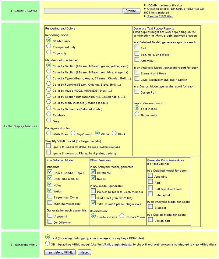
NISTIR 7822

               SteelVis User’s Guide
               (CIS/2 to VRML and IFC Translator)

                                       Robert R. Lipman

                                 Building Environment Division
                                        Engineering Laboratory

                                              September 2011
                                       (Updated January 2012)

                    U.S. DEPARTMENT OF COMMERCE
                            Rebecca Blank, Acting Secretary
NATIONAL INSTITUTE OF STANDARDS AND TECHNOLOGY
                                Patrick Gallagher, Director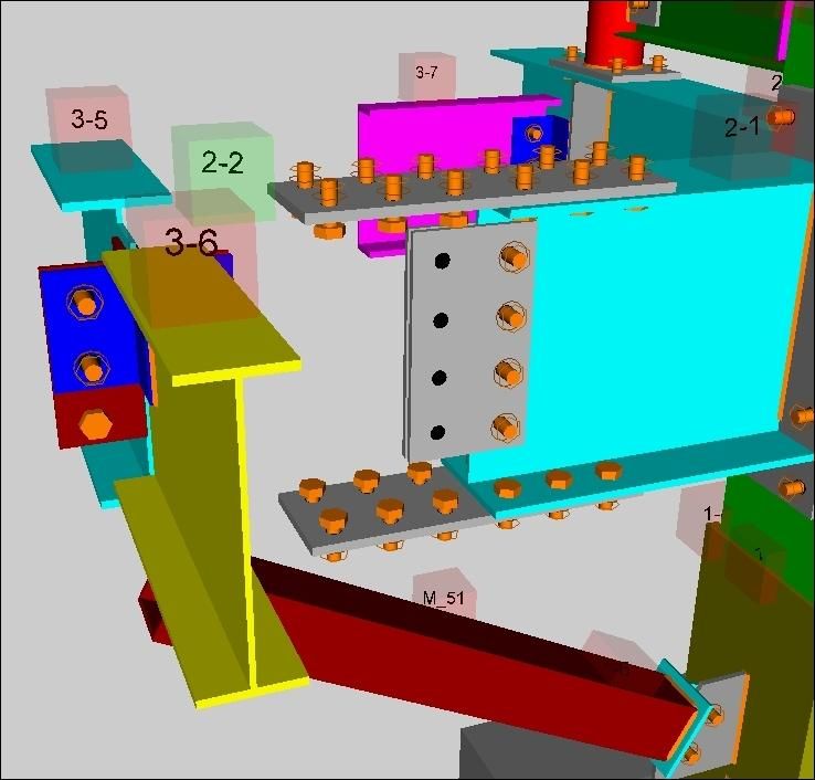
PREFACE

This guide describes how to use SteelVis and its associated programs. SteelVis has two main functions:
(1) to translate a CIS/2 (CIMsteel Integration Standards) file into an interactive 3D model in the form of a
VRML (Virtual Reality Modeling Language) file that can be displayed in a web browser VRML plugin or
VRML viewer and (2) to translate a CIS/2 file into an IFC (Industry Foundation Classes) file that can be
imported into many BIM (Building Information Modeling) applications. SteelVis also includes the CIS/2
File Analyzer that converts a CIS/2 file into a spreadsheet that can be used for inspecting and debugging
the attributes, values, and relationships in the CIS/2 file.

SteelVis used to be known only as the CIS/2 to VRML and IFC Translator.

More information about SteelVis, CIS/2, and IFC can be found at http://cic.nist.gov/vrml/cis2.html.

DISCLAIMERS

Any mention of commercial products in SteelVis and this user’s guide is for information purposes only; it
does not imply recommendation or endorsement by NIST. For any of the web links in SteelVis and this
user’s guide, NIST does not necessarily endorse the views expressed, or concur with the facts presented
on those web sites.

This software was developed at the National Institute of Standards and Technology by employees of the
Federal Government in the course of their official duties. Pursuant to Title 17 Section 105 of the United
States Code this software is not subject to copyright protection and is in the public domain. This software
is an experimental system. NIST assumes no responsibility whatsoever for its use by other parties, and
makes no guarantees, expressed or implied, about its quality, reliability, or any other characteristic.

Vendors of various software applications with CIS/2 export capabilities have supplied the sample CIS/2
files. The sample CIS/2 files do not necessarily reflect the current CIS/2 export capabilities of the
software packages represented nor are all software packages that have implemented CIS/2 represented.
NIST assumes no responsibility whatsoever for their use by other parties, and makes no guarantees,
expressed or implied, about their quality, reliability, or any other characteristic.

This software can be redistributed and/or modified freely provided that any derivative works bear some
notice that they are derived from it, and any modified versions bear some notice that they have been
modified. We would appreciate acknowledgement if the software is used.

ACKNOWLEDGEMENTS

Most of the development of SteelVis was carried out between 2003 and 2006 as part of the project
“Product Data Standards for Steel Construction” in the Computer Integrated Building Processes Group of
the Building and Fire Research Laboratory at NIST. The author thanks Dr. Kent Reed, former leader of
the group, for his support during the development of SteelVis. The author also acknowledges the many
software vendors and users who have provided invaluable feedback, suggestions, and bug reports about
SteelVis and supplied sample CIS/2 files that were used to test and improve the capabilities of SteelVis.

Cover image: Screenshot of SteelVis and associated types of output. Upper left – SteelVis user
interface; upper right – VRML model; bottom right – IFC file displayed in BIM software; bottom left –
CIS/2 converted to a spreadsheet.

                                                     iii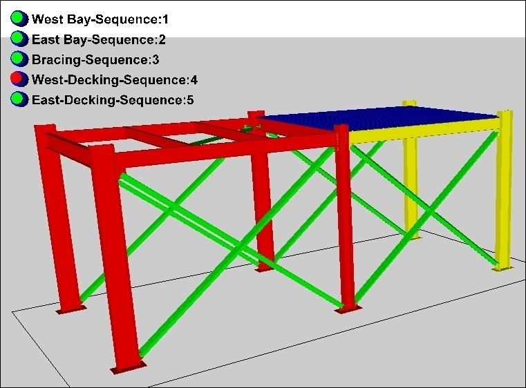
TABLE OF CONTENTS
1      INTRODUCTION ............................................................................................................................... 1
2      GETTING STARTED ......................................................................................................................... 1
    2.1      INSTALLING STEELVIS.................................................................................................................... 1
    2.2      RUNNING STEELVIS ........................................................................................................................ 2
    2.3      INSTALLING A VRML PLUGIN ........................................................................................................ 3
    2.4      TRANSLATING A CIS/2 FILE ........................................................................................................... 3
    2.5      VIEWING THE VRML MODEL......................................................................................................... 4
    2.6      UNINSTALLING STEELVIS............................................................................................................... 4
3      USER INTERFACE ............................................................................................................................ 5
    3.1 MENU BAR ...................................................................................................................................... 6
      3.1.1 File Menu ................................................................................................................................ 6
      3.1.2 Browsers Menu........................................................................................................................ 7
      3.1.3 Websites Menu ........................................................................................................................ 7
      3.1.4 Help Menu ............................................................................................................................... 7
    3.2 TABS BAR ....................................................................................................................................... 8
    3.3 STATUS TAB (FEEDBACK) .............................................................................................................. 8
      3.3.1 Error and Warning Messages ................................................................................................. 9
      3.3.2 Processing of Sections............................................................................................................. 9
    3.4 TRANSLATE BUTTONS .................................................................................................................. 12
4      VISUAL APPEARANCE .................................................................................................................. 13
    4.1 COLOR OPTIONS ........................................................................................................................... 13
      4.1.1 Background Color ................................................................................................................. 15
    4.2 RENDERING OPTIONS.................................................................................................................... 16
    4.3 TITLE, GROUND PLANE, ORIGIN AXES ......................................................................................... 18
    4.4 VIEWPOINTS.................................................................................................................................. 19
      4.4.1 User-Defined Viewpoints ...................................................................................................... 19
5      TEXT REPORTS .............................................................................................................................. 21
    5.1 SUMMARY REPORT ....................................................................................................................... 21
      5.1.1 Part List ................................................................................................................................. 22
      5.1.2 Material List .......................................................................................................................... 23
      5.1.3 Assembly List ......................................................................................................................... 24
      5.1.4 Bolt List ................................................................................................................................. 25
    5.2 WEIGHT IN TEXT REPORTS ........................................................................................................... 25
    5.3 TEXT POPUPS ................................................................................................................................ 26
      5.3.1 Text Popup in a Tooltip ......................................................................................................... 26
      5.3.2 Text Popup in the VRML Browser......................................................................................... 28
    5.4 MEMBER LABELS.......................................................................................................................... 29
6      MODEL SPECIFIC FEATURES .................................................................................................... 30
    6.1 DETAILED MODEL ........................................................................................................................ 30
      6.1.1 Copes, Camber ...................................................................................................................... 30
      6.1.2 Bolts, Holes, and Welds......................................................................................................... 31
      6.1.3 Sequences .............................................................................................................................. 34
      6.1.4 Excluding Parts ..................................................................................................................... 35
      6.1.5 Assemblies ............................................................................................................................. 36

                                                                            iv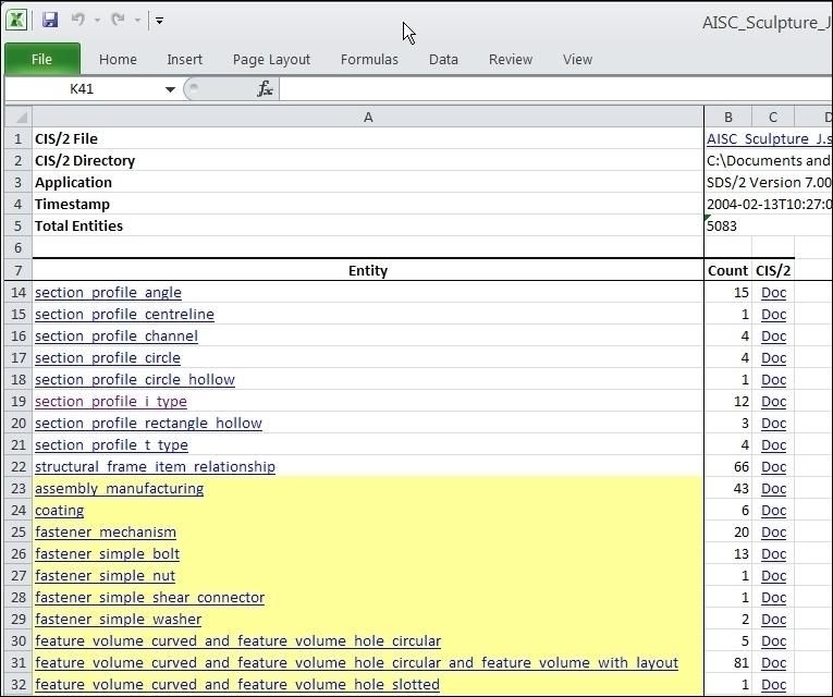
6.2 ANALYSIS MODEL ........................................................................................................................ 37
      6.2.1 Nodes and Wireframe ............................................................................................................ 37
    6.3 DESIGN MODEL ............................................................................................................................ 38
      6.3.1 Design Connections .............................................................................................................. 38
      6.3.2 Design Joint System .............................................................................................................. 39
7      OTHER FEATURES......................................................................................................................... 40
    7.1       GRID LINES ................................................................................................................................... 40
    7.2       VERTICAL AXIS ............................................................................................................................ 41
    7.3       MODEL TYPES .............................................................................................................................. 41
    7.4       CURVED PARTS ............................................................................................................................. 42
    7.5       NAVIGATION MODE ...................................................................................................................... 42
    7.6       MERGING MODELS ....................................................................................................................... 42
    7.7       X3D AND X3DOM ....................................................................................................................... 43
    7.8       SIMPLE VRML.............................................................................................................................. 44
    7.9       VRML PROTOS ........................................................................................................................... 44
8      DEBUGGING FEATURES .............................................................................................................. 46
    8.1       COORDINATE AXES ...................................................................................................................... 46
    8.2       CIS/2 FILE CHECKING .................................................................................................................. 46
    8.3       GENERATE EXCEL SPREADSHEET................................................................................................. 47
    8.4       FILE VALIDATION ......................................................................................................................... 50
9      GENERATING AN IFC FILE ......................................................................................................... 51
    9.1 SHAPE REPRESENTATION ............................................................................................................. 52
      9.1.1 Shape Representation Limitations ......................................................................................... 53
    9.2 ELEMENT REPRESENTATION......................................................................................................... 53
    9.3 UNITS ............................................................................................................................................ 55
    9.4 STORIES ........................................................................................................................................ 55
    9.5 DISPLAYING THE IFC FILE............................................................................................................ 55
    9.6 MORE IFC OPTIONS ...................................................................................................................... 56
      9.6.1 Analysis Model ...................................................................................................................... 56
      9.6.2 Assemblies ............................................................................................................................. 56
      9.6.3 Bolts, Welds, and Holes......................................................................................................... 57
      9.6.4 Property Sets ......................................................................................................................... 57
      9.6.5 Cardinal Point ....................................................................................................................... 57
    9.7 GLOBALLY UNIQUE ID ................................................................................................................. 57
10        COMMAND-LINE VERSION ..................................................................................................... 58
11        WEB SERVICES VERSION ........................................................................................................ 58
12        REFERENCES ............................................................................................................................... 62

                                                                              v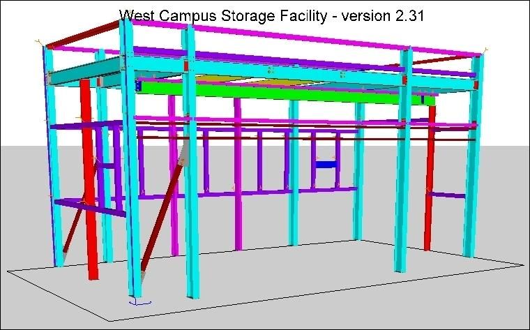
LIST OF FIGURES

Figure 1: SteelVis user interface ................................................................................................................... 5
Figure 2: File menu ....................................................................................................................................... 6
Figure 3: Browsers menu .............................................................................................................................. 6
Figure 4: Websites menu .............................................................................................................................. 8
Figure 5: Help menu ..................................................................................................................................... 8
Figure 6: Example of tooltip help ................................................................................................................. 8
Figure 7: Section types................................................................................................................................ 11
Figure 8: Colors tab options ........................................................................................................................ 13
Figure 9: Color by Section (1) .................................................................................................................... 14
Figure 10: Color by Section (2) .................................................................................................................. 14
Figure 11: Color by Type ............................................................................................................................ 14
Figure 12: Color by Function ...................................................................................................................... 14
Figure 13: Rendering tab options ................................................................................................................ 16
Figure 14: Transparent rendering................................................................................................................ 17
Figure 15: Edge rendering .......................................................................................................................... 17
Figure 16: Rendering options in VRML model .......................................................................................... 17
Figure 17: Ignoring thickness of members ................................................................................................. 17
Figure 18: Title, ground plane, and origin axes options ............................................................................. 18
Figure 19: VRML model with title, ground plane, and origin axes ............................................................ 18
Figure 20: Generate viewpoint options ....................................................................................................... 19
Figure 21: VRML model with viewpoint text ............................................................................................ 20
Figure 22: Reports tab options .................................................................................................................... 21
Figure 23: Summary report part list ............................................................................................................ 22
Figure 24: Summary report material list ..................................................................................................... 23
Figure 25: Summary report assembly list ................................................................................................... 24
Figure 26: Summary report bolt list ............................................................................................................ 25
Figure 27: Tooltip text popup in Cortona3D .............................................................................................. 26
Figure 28: Tooltip text popup in Cosmo Player .......................................................................................... 26
Figure 29: Tooltip text popup with assembly information in a separate web browser window ................. 27
Figure 30: Text popup in the VRML browser ............................................................................................ 28
Figure 31: Member labels ........................................................................................................................... 29
Figure 32: Detailed model options .............................................................................................................. 30
Figure 33: Parts with copes (cutouts) .......................................................................................................... 31
Figure 34: Parts with bolts, nuts, washers, holes, welds, shear stud ........................................................... 32
Figure 35: Parts with holes and welds ........................................................................................................ 32
Figure 36: Welds represented by an orange weld symbol .......................................................................... 33
Figure 37: Structure with sequences ........................................................................................................... 34
Figure 38: Structure with non-main parts and plates excluded ................................................................... 35
Figure 39: Structure with assembly on-off switches ................................................................................... 36
Figure 40: Analysis model options ............................................................................................................. 37
Figure 41: Analysis model wireframe and nodes........................................................................................ 37
Figure 42: Design model options with tooltip help..................................................................................... 38
Figure 43: Internal design connection between four parts .......................................................................... 38
Figure 45: Orthogonal and radial grid lines ................................................................................................ 40
Figure 46: Grid lines and levels .................................................................................................................. 41
Figure 47: Model with design and analysis models .................................................................................... 41
Figure 48: Merging VRML model options in the VRML tab ..................................................................... 42
Figure 49: Merged VRML models.............................................................................................................. 43
Figure 50: Interactive 3D model ................................................................................................................. 45

                                                                             vi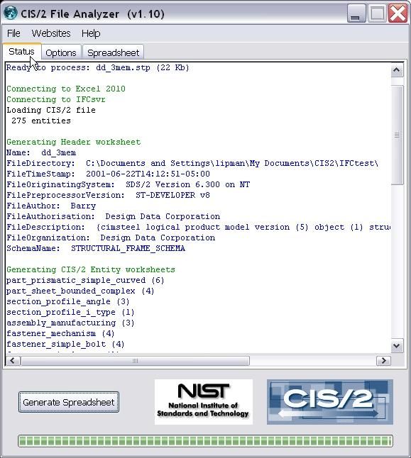
Figure 51: Debug tab options ...................................................................................................................... 46
Figure 52: Assembly and part coordinate axes ........................................................................................... 47
Figure 53: Part and bolt coordinate axes ..................................................................................................... 47
Figure 54: CIS/2 file with indentation ........................................................................................................ 47
Figure 55: CIS/2 File Analyzer user interface ............................................................................................ 48
Figure 57: Summary worksheet .................................................................................................................. 49
Figure 58: Worksheet for the material entity .............................................................................................. 50
Figure 59: IFC file generation options ........................................................................................................ 51
Figure 60: Structure colored by IFC type (element representation)............................................................ 55
Figure 61: More IFC file generation options .............................................................................................. 56
Figure 62: Command-line version options (partial list) .............................................................................. 59
Figure 63: Feedback when running the command-line version .................................................................. 60
Figure 64: SteelVis web services version ................................................................................................... 61

                                                                         vii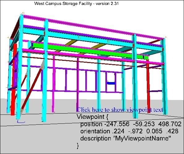
1     Introduction

The CIMsteel Integration Standards (CIS/2) [1, 2] are the product model and electronic data exchange
format for structural steel project information. CIS/2 is intended to enable a seamless and integrated flow
of information among all parties of the steel supply chain involved in the design, analysis, engineering,
fabrication, and construction of steel framed structures. The CIS/2 standard covers everything from nuts
and bolts to materials and loads to frames and assemblies. Structures can be represented as design,
analysis, or detailed models. Detailed models are also known as manufacturing, physical, or fabrication
models. CIS/2 has been implemented as a file import and/or export capability in many steel design,
analysis, engineering, fabrication, and construction software packages.

Using SteelVis as a CIS/2 file viewer provides a way to visually verify the information in a CIS/2 file and
to provide feedback about many of the attributes of the structural steel model. To visualize a CIS/2 file,
SteelVis generates a VRML (Virtual Reality Modeling Language) file [3, 4] which can be viewed in a
web browser VRML plugin, VRML viewers, or other software that can display VRML files.

Using SteelVis to translate a CIS/2 file into an Industry Foundation Classes (IFC) file [5] allows
information about a steel structure to be imported into Building Information Modeling (BIM) software
that can only import IFC files and not CIS/2 files. The capability to import the CIS/2 model into BIM
software allows for coordination between the structural steel model and other parts of the structure such
as concrete and mechanical and electrical systems. IFC is the product model and electronic data
exchange format to facilitate interoperability between software applications in the building industry. It is
developed by buildingSMART [6], formerly known as the International Alliance for Interoperability.

The CIS/2 to VRML Translator was first developed in 2000 as a command-line program that ran on a
Silicon Graphics workstation. In 2001, the web services version of the translator was made available
online. In 2003, the Windows version with a graphical user interface was developed. In 2005, the
capability to translate from a CIS/2 file to an IFC file was added to SteelVis. This User’s Guide for
SteelVis was written in 2011.

2     Getting Started

2.1        Installing SteelVis
The download request form for SteelVis can be found at
http://ciks.cbt.nist.gov/cgi-bin/ctv/ctv_request.cgi. After submitting the download request, instructions
about where to download SteelVis will be provided. The information is also emailed to the requestor.
SteelVis is downloaded as a zip file named CTV.zip. The file is named CTV for CIS/2 To VRML.

The installation process does not require anything more than unzipping the file CTV.zip. This will
create a directory named CTV containing six files:

      1. CIS2_VRML.exe – SteelVis graphical user interface (GUI) version
      2. ctv.exe – SteelVis command-line version, no GUI, (section 10 below)
      3. ctv-64.exe – Version of ctv.exe that runs only on 64-bit computers
      4. CIS2_Excel.exe – CIS/2 File Analyzer generates an Excel spreadsheet from a CIS/2 file,
         (section 8.3 below)
      5. SteelVis-README-FIRST.pdf – A brief introduction to SteelVis
      6. SteelVis-Users-Guide.pdf – This user’s guide

                                                     1
There are no restrictions as to where the CTV directory is located in the computer’s file system, however,
the four executable files and the User’s Guide in the CTV directory should not be moved from the
directory.
2.2 Running SteelVis
SteelVis can run on any Windows 7, XP, or Vista computer. There are no minimum system requirements
for SteelVis although as with any computer program, more memory, a fast computer processor, and more
graphics memory is better. SteelVis (CIS2_VRML.exe) is a 32-bit application. The size of the CIS/2
file that can be translated by SteelVis depends on the amount of computer memory and SteelVis options
selected. CIS/2 files greater than approximately 200 MB might require using the 64-bit command-line
version of SteelVis (ctv-64.exe) and a computer with more than 2 GB of memory.
To run SteelVis, simply double click on the icon for CIS2_VRML.exe. The first time SteelVis is run
several setup functions are performed:
1. The user is asked if a shortcut to SteelVis can be created in the Start Menu and if an icon for
SteelVis can be placed on the Desktop. The SteelVis icon is a cartoon representation of an I-
beam. Creating the shortcut and icon facilitates running SteelVis without having to remember
where it is installed. A shortcut to SteelVis is also created in the CTV directory.
2. If more than one web browser is installed on the computer, the user is asked to select the default
web browser to use with SteelVis. The selected web browser should be the web browser where a
VRML plugin is already or will be installed. This selection can be changed later in the Browsers
menu of SteelVis (section 3.1.2 below). SteelVis detects if the following web browsers are
installed on the computer: Internet Explorer, Firefox, Google Chrome, Opera, and Safari.
3. A welcome dialog is displayed that indicates that the VRML Plugin Detector will run after
clicking OK. The VRML Plugin Detector is described in section 2.3 below.
4. A file SteelVis_options.dat is created in the user’s home directory that stores the current
state of the SteelVis options. Do not edit this file.
Also, the first time SteelVis is run, two directories html and sample are created in the CTV directory
and several utility and sample CIS/2 files are written to those directories. The second time SteelVis is
run, the Disclaimers dialog is displayed.
The sample directory contains seven CIS/2 files:
cis2_analysis.stp – analysis model, display options are described in section 6.2 below
cis2_design.stp – design model, display option are described in section 6.3 below
cis2_detailed.stp – detailed model, shown in Figure 37 below, display options are described
in section 6.1 below
cis2_curved.stp – detailed model of curved beams, see section 7.4 below
cis2ifc_test1.stp, cis2ifc_test2.stp – use to test IFC Shape Representation and
Cardinal Point, (sections 9.1 and 9.6.5 below)
cis2ifc_test3.stp – all section types, see Figure 7 below
The sample CIS/2 files can be used to understand and test: (1) various features of SteelVis, (2) how a
VRML plugin or viewer displays a VRML model, (3) how a CIS/2 file is translated to an IFC file, and (4)
how an IFC application imports and displays the IFC file.
22.3 Installing a VRML Plugin
To visualize a CIS/2 file, SteelVis generates a VRML (Virtual Reality Modeling Language) file. VRML
is a standard file format that is used to display 3D models in a web browser VRML plugin or other
VRML viewer. Without a VRML plugin or viewer, the 3D interactive model of the CIS/2 file cannot be
displayed.
The VRML Plugin Detector runs in the web browser that was selected in step 2 above. It determines
which, if any, VRML plugin is installed in the web browser. It does not detect other VRML viewers. A
security warning might be displayed when running the VRML Plugin Detector in Internet Explorer. In
this case click on the warning and select “Allow Blocked Content…”.
If a VRML plugin is installed, then a sample VRML model, which was generated from a CIS/2 file, is
also displayed. If a VRML plugin is not detected, then a list of VRML plugins that work with SteelVis is
provided. Currently, those VRML plugins are:
BS Contact - http://www.bitmanagement.com/en/products/interactive-3d-clients/bs-contact
Cortona3D Viewer - http://www.cortona3d.com/Products/Cortona-3D-Viewer.aspx
Cosmo Player – http://cic.nist.gov/vrml/cosmoplayer.html
Flux Player - http://mediamachines.wordpress.com/flux-player-and-flux-studio/
Octaga Player – http://octagavs.com/softwarem/octaga-player
Select one of the VRML plugins and follow the instructions that come with the VRML plugin to install it
in the web browser. All of the VRML plugins can be installed in Internet Explorer and Firefox and some
can also be installed in Google Chrome, Opera, and Safari. Some of the VRML plugins will install in the
64-bit version of Internet Explorer. Although Cosmo Player is available from the NIST web site, it was
not developed at NIST.
A license is available for purchase with BS Contact, Cortona3D Viewer, and Octaga Player. The license
removes the product logo from the VRML browser window. BS Contact, Flux Player, and Octaga Player
also come with standalone VRML viewers that do not require a web browser to run in. They can also be
used by SteelVis to display VRML models (section 3.1.2 below).
All of the VRML plugins have been tested to ensure that they work correctly with SteelVis. The main
difference between the VRML plugins is how the user interacts with the VRML model that is displayed.
All of the VRML plugins allow the user to rotate, pan, and zoom the VRML model; however, each uses
different functionality for the mouse buttons and menu items.
2.4 Translating a CIS/2 File
After a VRML plugin or viewer is installed, a CIS/2 file can be translated into a VRML model by
opening up a CIS/2 file from the File menu (section 3.1.1 below) and clicking on the Translate and
Display button (section 3.4 below).
The display options in the user interface that affect the appearance of the VRML model are described in
the sections 3 through 8. Every time the display options are changed, the CIS/2 file must be translated
and displayed again. The VRML model cannot be updated without translating the CIS/2 file. Selecting
some display options might enable or disable other display options.
If the CIS/2 file is named mycis2file.stp, then the resulting VRML file will be named
mycis2file_ctv.wrl. The file extension for VRML files is “wrl”.
3SteelVis cannot translate an IFC file into a CIS/2 file, although some research related to this topic was
done at Georgia Tech [7]. It also cannot translate a VRML file into a CIS/2 file or IFC file. However,
there is limited support for translating some types of CIS/1 and DSTV files to VRML files.
2.5 Viewing the VRML Model
Once the VRML model is displayed in the VRML plugin or viewer, the user can interactively navigate
around the 3D model. How the user interacts with the model depends on the VRML plugin. For some of
the display options, small round buttons will appear in the VRML browser that the user can click on to
toggle on and off parts of the model. The functionality of the buttons depends on the VRML plugin.
A security warning might be displayed when trying to view a VRML model with a VRML plugin in
Internet Explorer. In this case click on the warning and select “Allow Blocked Content…”.
2.6 Uninstalling SteelVis
SteelVis can be uninstalled by manually deleting several files and directories. Deleting the CTV directory
will remove the SteelVis executable and associated files. In a user’s home directory, the file
SteelVis_options.dat can be deleted. Finally, the desktop icon for SteelVis can be deleted.
43 User Interface
Figure 1 shows the SteelVis user interface running on a Windows XP computer. The appearance and
functionality of the interface on a Windows 7 or Vista computer is similar.
At the top of the user interface is the Menu Bar with the File, Browsers, Websites, and Help menus.
Below that is the Tabs Bar with one tab for the Status window and the other tabs that provide access to all
of the display options. Below that is the Status window that shows the text feedback when SteelVis is
running. Clicking on one of the other tabs will switch to the user interface for that tab. At the bottom is a
row of four buttons and four images.
< Menu Bar
< Tabs Bar
< Status Tab and
display options
< Translate Buttons
Figure 1: SteelVis user interface
53.1 Menu Bar
3.1.1 File Menu
From the File menu, shown in Figure 2, the user can select which CIS/2 file to open for translation.
Multiple CIS/2 files can also be processed at one time. The user will be asked to select a directory to
search for CIS/2 files. The search for multiple files can be restricted to only the selected directory or to
include all subdirectories.
Below the first solid line in the File menu is a list of up to 20 of the most recently translated CIS/2 files
which can be opened directly. The function keys F1 and F2 can be used to Translate and Display or Only
Translate, respectively, the CIS/2 file that was most recently translated. In addition to using the functions
keys F1 and F2, the Translate and Display and Translate Only options can be selected from the bottom of
the File menu.
Below the list of CIS/2 files is a link to download a zip file of 25 sample CIS/2 files. The zip file also
contains X3DOM files that can be displayed without a VRML plugin or viewer (section 7.7 below) and
Excel spreadsheets (section 8.3 below) generated from the sample CIS/2 files. Other sample CIS/2 files
are located in the sample subdirectory of the CTV directory where SteelVis is installed. An explanation
of those files is found in section 2.2 above.
The Export Preferences option allows the user to export the current state of the SteelVis display options to
a user-defined file. That file can be imported to SteelVis with the Import Preferences option. Preferences
are a useful way to save and restore commonly used settings of SteelVis display options.
Any VRML or IFC file can be displayed again with the Redisplay Any File option which can also be
accessed with the F3 function key.
Figure 2: File menu Figure 3: Browsers menu
63.1.2 Browsers Menu
The Browsers menu, shown in Figure 3, is used to select which web browser, viewer, or program will
display the VRML file when the Translate and Display or Display Again buttons (section 3.4 below) are
clicked. It shows a list of programs installed on the user’s computer where a VRML file might be
displayed. Programs are listed in the Browsers menu if they are installed in their default locations such as
C:\Program Files or if there is a shortcut to them on the desktop. The list of web browsers will always
contain all web browsers found on the computer regardless if they have a VRML plugin installed in them.
At a minimum, the Browsers menu will always contain Internet Explorer and the WordPad text editor.
If a VRML file has already been generated, the user can select a different program in the Browsers menu
and then click the Display Again button (section 3.4 below) to display the VRML file in the selected
program.
In the example list of browsers, Deep View 6, Instant Player, Xj3D, and Adobe 3D Reviewer are viewers
that display VRML files. Acrobat 9.0 Pro Extended is software used to embed a VRML file in a PDF
document. Chisel is a VRML file optimizer, VrmlPad is a VRML file editor, and TextPad is a text editor
similar to WordPad. VRML viewers, such as BS Contact and Flux Player that come with their associated
VRML plugins, can also appear in the Browsers menu.
3.1.3 Websites Menu
The Websites menu, shown in Figure 4, provides links to useful resources related to SteelVis, VRML,
CIS/2, and IFC.
3.1.4 Help Menu
The Help Menu, shown in Figure 5, has four sections. In the first section, “What’s New” displays
information in the Status tab about new features in SteelVis. The “What’s New” information is
automatically displayed every time a new version of SteelVis is run.
“Check for Update” opens up a web page that checks for the latest version of SteelVis. Follow the
instructions on that web page to download a new version of SteelVis if one is available. The “Check for
Update” feature runs automatically if an update hasn’t been checked for in the last 30 days.
“VRML Plugin Detector” runs the same check for a VRML plugin described in section 2.3 above.
Selecting the other topics in the Help menu displays information related to them in the Status tab.
Help is also available in the form of tooltips related to the display options in the tabs. Holding the mouse
over any text in a tab for a second or two will display a tooltip. An example of tooltip help in the Detailed
tab is shown in Figure 6.
Previous to this user’s guide, the Help menu and tooltips were the only documentation available for
SteelVis.
7Figure 4: Websites menu
Figure 5: Help menu
Figure 6: Example of tooltip help
3.2 Tabs Bar
The tabs bar is located directly below the menu bar in Figure 1. Clicking on a tab will switch from the
current tab to the selected tab. Except for the Status tab, the other tabs contain all of the SteelVis display
options similar to Figure 6 above. The display options in the tabs will be described in the sections below,
in the context of their function rather than in the order of the tabs.
3.3 Status Tab (Feedback)
The Status tab displays important feedback during the translation of a CIS/2 file. The information should
not be ignored as it provides useful insight as to why the resulting VRML model or IFC file may not
8appear as expected. A brief example of the information in the Status tab is shown in Figure 1. The types
of messages that appear in the Status tab will depend on the CIS/2 file that is translated.
The following is the general sequence of most of the information that appears in the Status tab when a
CIS/2 file is translated:
Name of the program that generated the CIS/2 file and the time stamp in the CIS/2 file
Progress is indicated by a counter that increments by 5000 while the lines of the CIS/2 file are
read
Total CIS/2 entities read
A list of all translated CIS/2 entities including the number of each entity
A list of all ignored CIS/2 entities that includes all entities not recognized by SteelVis or those
that do not have to be processed depending on the selected display options
CIS/2 model type: Design, Analysis, or Detailed or any combination of the three
Messages about processing of units, lengths, coordinates, sections, copes, bolts, holes, openings,
and assemblies depending on the CIS/2 model type. Particular attention should be paid to the
messages about “Processing: sections” (section 3.3.2 below).
Messages about generating the VRML model
Messages about generating the Summary Report if the option is selected, (section 5.1 below)
Messages about generating an IFC file if the option is selected, (section 9 below)
Names of the files that were generated and their size
Current configuration of the display options
3.3.1 Error and Warning Messages
The text or background color of the messages in the Status tab has significance:
Messages with a yellow background or red text are errors, warnings, or informational
Messages with a light blue background are related to generating an IFC file, (section 9 below)
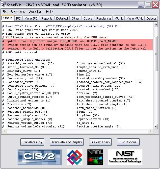
Messages with a red background are syntax errors in the CIS/2 file and indicate a non-
conformance to the CIS/2 schema, however, SteelVis does not check for all syntax errors.
Conformance to the schema and complete syntax checking can be performed with other tools,
(section 8.4 below). Use the option for ‘More warning and error messages’ in the Debug tab to
report specific CIS/2 entities that are the cause of some syntax errors.
Any of the error or warning messages might affect how the CIS/2 file is translated into a VRML model or
IFC file. However, any of the error or warning messages, including syntax errors, does not necessarily
imply that the CIS/2 file cannot be used successfully to exchange information with other software
applications.
3.3.2 Processing of Sections
The information in the Status tab regarding processing of sections can contain information about a
common source of problems regarding the visual appearance the resulting VRML model. A CIS/2 file
can specify the explicit dimensions of sections such as the depth, width, web thickness, and flange
thickness for an I-beam and other section types. In this case, there is no ambiguity as to what the section
dimensions are and how parts with those sections will appear in the VRML model. If there are entities
such as Section_profile_i_type, Section_profile_angle and other similarly named
entities in the Status tab feedback related to the “Translated CIS/2 entities”, then these are CIS/2 entities
that explicitly specify the dimensions of those sections.
9However, it is also valid for a CIS/2 file to only specify the section designator such as W14X120 without
any section dimensions. If the entity Section_profile is present, then only the section designator is
used to specify the section. In this case, an internal lookup table is used to find the dimensions for the
section. The lookup table contains the section dimensions for over 4400 of the most commonly used
sections from around the world. Also included in the lookup table are equivalent names for the same
sections. For example, a 75PFC and 75X40X6PFC refer to the same section and have the same
dimensions. Similarly, an HEA100 and HE100A refer to the same section and a W14X61 and W14*61
also refer to the same section. The section designator that is used in the CIS/2 file is completely
dependent on the software that generated the CIS/2 file.
Some section types, such as angles and rectangular sections, are not included in the lookup table and the
dimensions can usually be parsed directly from the section designator. For example, an L250X125X13 is
interpreted as an angle that is 250 mm deep, 125 mm wide, and has a thickness of 13 mm.
In the VRML model, for all sections, webs and flanges always have constant thickness, and the fillets
between webs and flanges are ignored. Leg slope for angles is also ignored.
If the dimensions for a section cannot be found in the lookup table then the section dimensions and
section type (I-beam, angle, channel, etc.) will be parsed or approximated from the section designator.
However, sometimes that approximation is wrong and the resulting VRML model will look incorrect for
those sections that are approximated. For example, if the section designator is only given as “SSMM-12”,
there is no way to know what the section dimensions or type is. In this case a rectangular section is used.
There can also be ambiguities when interpreting the units of the numbers in the section designator. If a
number in a section designator (for example the “12” in “SSMM-12”) is interpreted to be in inches when
it is actually millimeters, then the section will appear much too large.
In the Status tab, if the CIS/2 file contains only explicit section dimensions, then there is no feedback for
the “processing of sections”. However, if the CIS/2 file contains any sections that are specified only by
the section designator, then the feedback in the Status tab can contain any or all of the following
information:
Number and name of sections found in the lookup table
Number and name of sections that were parsed from the section designator
Number and name of sections that were approximated from the section designator and their
approximated dimensions and type
Number and name of sections that were not recognized
Sections that are parsed, approximated, or not recognized might look wrong in the VRML model.
The location of the longitudinal axis of a part relative to its cross section is known as the cardinal point in
CIS/2. The most common cardinal points such as top-of-steel or center of the section are processed,
however, cardinal points for double sections, joists, and edge-defined sections are ignored. If the cardinal
point is ignored or approximated, then the part will appear slightly offset from its actual location.
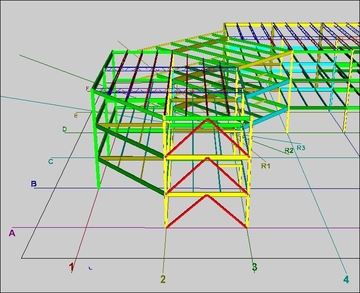
103.3.2.1 Section Types
Figure 7 shows an example of most of the different types of sections that SteelVis can write to a VRML
file. They are specified with explicit section dimensions or from dimensions found in the lookup table.
The CIS/2 file for this example is cis2ifc_test3.stp in the sample directory (section 2.2 above).
Row-by-row starting from the bottom left, the section types are:
I-beam, T-beam, channel, angle, cold-formed channel
Solid circular, hollow circular, solid rectangular, hollow rectangular, cold-formed zee
Tapered beam, plate, double channel, double angle, joist
Bent plate, corrugated decking, curved beam
The representation of joists is only an approximation because the only information in a CIS/2 file about a
joist section is its depth. All joists are represented by double angles for the top and bottom chords and
rectangular bars for the web.
Figure 7: Section types
113.4 Translate Buttons
The translate buttons are located at the bottom of the user interface, as shown in Figure 1, and have the
following functions:
Translate Only – Translate the CIS/2 file and generate a VRML model, however, it is not
displayed. Optionally, an IFC file can also be generated, (section 9 below).
Translate and Display – Same as Translate Only but the VRML model is displayed in whatever
web browser or viewer is selected in the Browsers menu (section 3.1.2 above). Optionally, an
IFC file can also be generated (section 9 below).
Display Again – Redisplay the VRML model in whatever web browser or viewer is selected in
the Browsers menu (section 3.1.2 above). This is useful to display the same VRML model in
different VRML plugins, viewers, or editors without have to retranslate the CIS/2 file.
List Options – The current display options are listed in the Status tab.
Below the Translate buttons are four images related to CIS/2, VRML, IFC, and NIST. The images are
links to web sites associated with the image.
124 Visual Appearance
Many options are available to change the visual appearance of the VRML model. Most of the settings for
those options are found in the Colors, Rendering, and Other tabs. Some of the options are applicable only
to certain types of CIS/2 models or features in a CIS/2 file. Some options are disabled or enabled
depending on the selection of other options. Every time the display options are changed, the CIS/2 file
must be translated and displayed again. The VRML model cannot be updated without translating the
CIS/2 file.
4.1 Color Options
The options to change the colors assigned to members in the VRML model are found in the Colors tab as
shown in Figure 8.
Figure 8: Colors tab options
Figures 9 through 12 are examples of the same VRML model colored using the first four color options.
Figure 9 shows the model using the first Color by Section option. For this option all I-beams and T-
beams are green, dark green, yellow, dark yellow, or cyan (light blue). All other sections except plates
are red, blue, magenta, and purple. Bolts and welds are always orange. Anything considered to be a plate
is always grey. Shear studs are always beige. Members with the same cross section always have the
same color, however, members with the same color do not always have the same cross section. Figure 10
shows the model using the second Color by Section option. This is the same as the first option except that
the color palette for the members is reversed.
Figure 11 shows the model using the Color by Type option which assigns colors to the members based on
their cross section type, i.e. I-beam, angle, channel, etc. A legend shows the colors assigned to each type.
Figure 12 shows the model using the Color by Function option which assigns colors to the members
13based on their function. How functions are specified for the members is completely dependent on the
software that generated the CIS/2 file. If functions are assigned to members they are displayed in the
Summary Report (section 5.1.1 below).
Figure 9: Color by Section (1) Figure 10: Color by Section (2)
Figure 11: Color by Type Figure 12: Color by Function
14The other options to color the VRML model are:
Color by Grade – Similar to Color by Function except that the name of the material assigned to a
member is used as the basis for the color.
Color by Section Dimension – Color is assigned based on how the dimensions for a member’s
cross section are determined, (section 3.3.2 above).
Color by IFC Type – Color is assigned based on the type of IFC entity used for a member,
(section 9.2 below and Figure 60). This option is enabled when an IFC file is generated from the
CIS/2 file.
Color by Main Member – Some CIS/2 files differentiate between the main member of an
assembly (e.g. a beam) and the other members in the assembly (e.g. angle brackets and gusset
plates). All main members will be one color and the other members another color. CIS/2 files
that contain main members use the entity Located_part_marked. These entities can be
checked for in the Status tab in the “Translated CIS/2 entities” section.
Color by Sequence – Color is assigned based on groupings of members by sequences or zones.
All members in the same sequence or zone will have the same color. This option is enabled
when sequences and zones are translated in a detailed model, (section 6.1.3 below and Figure
37).
Color by Surface Treatment – Color is assigned to members based on their surface treatment.
CIS/2 files with member surface treatment have the entities Coating and
Surface_treatment.
Color by Fabrication Status – Color is assigned to members based on their fabrication status.
CIS/2 files with fabrication status information are not very common. If this option is selected
and the CIS/2 file contains the necessary entities need to assign colors, then after processing of
the CIS/2 file has started, a dialog will appear and the status parameter can be selected that will
be used to color members.
Color by Application – Color is assigned to members based on which software application
created the member. CIS/2 files with application information are not very common.
Rainbow – Color is assigned to members randomly.
Grey – All members are colored grey.
Parts that cannot be assigned a color based on the selected color option will appear grey. If a color option
is selected that does not apply to the type of CIS/2 model being translated, then the entire VRML model
will appear grey and a message will appear in the Status tab.
4.1.1 Background Color
Four different background colors can be displayed in the VRML model: white/grey, white, black, and
sky/ground. The white/grey background is used in all of the figures with VRML models.
154.2 Rendering Options
The options to change how members are rendered in the VRML model are found in the Rendering tab as
shown in Figure 13.
Figure 13: Rendering tab options
Figures 14 through 17 are examples of the same VRML model with displayed with different rendering
options. In Figure 14, all of the members, bolts, holes, and welds are transparent. The anchor rods in the
base of the structure are now visible. Figure 9 is the same model displayed with shaded (non-transparent)
rendering.
In Figure 15, most of the members are displayed only by their edges. Bolts, holes, and welds are
displayed only with lines. Bent plates, corrugated decking, and curved parts cannot be displayed by only
their edges.
Figure 16 uses the fourth option in the Rendering tab for shaded, transparent, edge, and wireframe. This
option requires the “VRML with PROTOs” option in the More VRML tab (section 7.9 below). The
different rendering options can be selected directly in the VRML display. In this VRML model, there are
also buttons to toggle on and off the bolts, holes, and welds. This rendering option is not recommended
for very large CIS/2 models.
Figure 17 shows the VRML model with all three of the Simplify VRML Model options turned on.
Ignoring the thickness of member greatly reduces the number of surfaces that have to be displayed in the
VRML model. This is useful for very large CIS/2 models or when displaying the VRML model on
slower computers. Bolts, holes, and welds are displayed only by lines. Since the base of the structure is
modeled as a plate, it is displayed as a surface through the middle of the plate.
16You can also read