Cisco DNA Application Assurance - Solutions Adoption Prescriptive Reference-Design Guide
←
→
Page content transcription
If your browser does not render page correctly, please read the page content below

Cisco DNA Application Assurance
Solutions Adoption Prescriptive Reference—Design Guide
March, 2020

                              1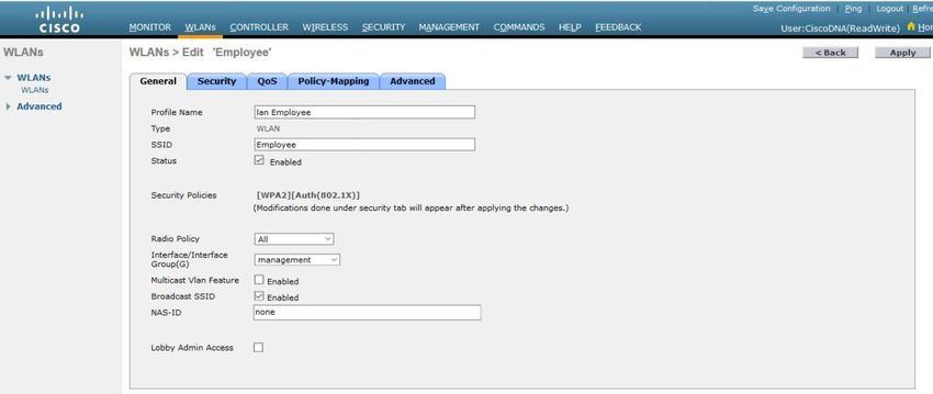
Table of Contents
Introduction .................................................................................................................................................................................................................. 4
    About the Solution................................................................................................................................................................................................... 4
    About This Guide ..................................................................................................................................................................................................... 4
Define the Network for Cisco DNA Application Assurance .......................................................................................................................................... 6
    Audience .................................................................................................................................................................................................................. 6
    Purpose of this Document ....................................................................................................................................................................................... 6
    Solution Overview ................................................................................................................................................................................................... 6
         Assumptions ....................................................................................................................................................................................................... 7
Design the Network for Cisco DNA Application Assurance .......................................................................................................................................... 8
    Cisco IOS-XE Router Platforms – Application Experience Data ............................................................................................................................... 9
         Where to Enable Cisco DNA Application Assurance on Cisco IOS-XE Router Platforms? ................................................................................ 10
    Cisco Catalyst 9000 Series Switch Platforms – Application Visibility Data ............................................................................................................ 13
         Where to Enable Cisco DNA Application Assurance on Cisco Catalyst 9000 Series Switch Platforms? ........................................................... 13
    Cisco AireOS WLC Platforms – Application Visibility Data..................................................................................................................................... 15
         Where to Enable Cisco DNA Application Assurance on Cisco AireOS WLC Platforms? ................................................................................... 15
    Deployment Guide Implementation...................................................................................................................................................................... 15
         Wide Area Network (WAN) .............................................................................................................................................................................. 15
         Local Area Network (LAN)................................................................................................................................................................................. 16
         Wireless Local Area Network (WLAN) .............................................................................................................................................................. 17
Deploy Cisco DNA Application Assurance on the Network ........................................................................................................................................ 19
         Procedure: Configure the IOS XE Router Interfaces for Cisco DNA Application Assurance ............................................................................. 19
         Procedure: Configure the Catalyst 9000 Series switch ports for Cisco DNA Application Assurance ............................................................... 21
         Procedure: Configure the AireOS WLCs for Cisco DNA Application Assurance ............................................................................................... 23
         Procedure: Configure IOS XE Routers, Catalyst 9000 Series Switches, and AireOS WLCs for Maximal Telemetry within Cisco DNA Center . 26
Operate the Network ................................................................................................................................................................................................. 34
    Use Case #1: View Application Traffic across the LAN .......................................................................................................................................... 34
         Use Case Scenario ............................................................................................................................................................................................. 34
         Procedure: Use Cisco DNA Application Assurance to View Application Traffic on Catalyst 9000 Series Switches ........................................ 34
         Use Case Summary ........................................................................................................................................................................................... 38
    Use Case #2: View Application Traffic across the WLAN....................................................................................................................................... 38
         Use Case Scenario ............................................................................................................................................................................................. 38
         Procedure: Use Cisco DNA Application Assurance to View Application Traffic on AireOS WLCs ................................................................... 38
         Use Case Summary ........................................................................................................................................................................................... 44
    Use Case #3: Identifying and Troubleshooting an Application Performance Issue ............................................................................................. 44
         Use Case Scenario ............................................................................................................................................................................................. 44
         Procedure: Determine if the Application has Degraded Health ...................................................................................................................... 44

                                                                                                               2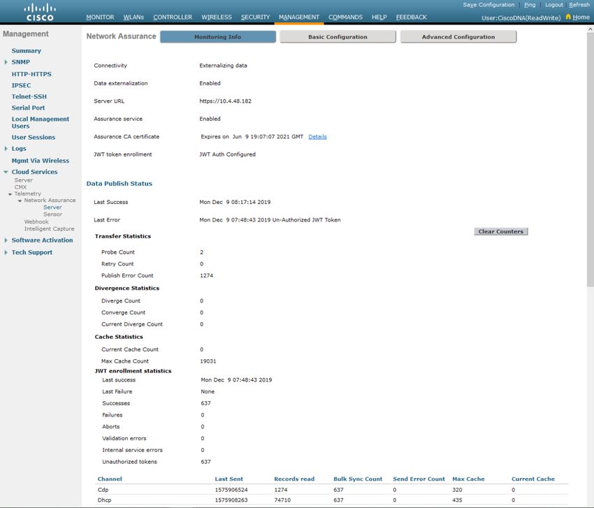
Procedure: Determine Where in the Network the Application Health Issues are Occurring ......................................................................... 47
         Procedure: Determine if the Application Health Issues are Network Related ................................................................................................ 48
         Use Case Summary ........................................................................................................................................................................................... 55
Appendix A—New in this guide .................................................................................................................................................................................. 56
Appendix B—Hardware and software used for validation ........................................................................................................................................ 57
Appendix C – Viewing Cisco DNA Application Assurance Data .................................................................................................................................. 58
         Procedure: Viewing Application Information within the Application Health Dashboard ............................................................................... 58
         Procedure: Viewing Application Information within the Application 360 Dashboard .................................................................................... 66
         Procedure: Viewing Application Information within the Device 360 Dashboard ........................................................................................... 74
         Procedure: Viewing Information within the Device 360 Dashboard............................................................................................................... 78
Appendix D—Glossary ................................................................................................................................................................................................ 80
About this guide ......................................................................................................................................................................................................... 81
    Feedback & Discussion .......................................................................................................................................................................................... 81

                                                                                                             3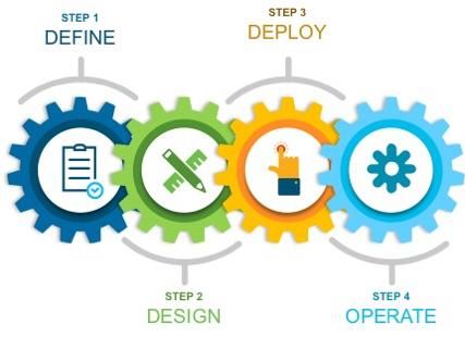
Introduction

Introduction

About the Solution
    This solution focuses on how to deploy Cisco DNA Application Assurance within an enterprise network; and how to monitor
    and troubleshoot applications and their performance when the application traffic crosses observation points within the LAN
    & WAN, through Cisco DNA Application Assurance.

    Cisco DNA Application Assurance is only one component of Cisco DNA Assurance which runs on Cisco DNA Center. Other
    components include Cisco DNA Network Assurance, Cisco DNA Client Assurance, Intelligent Capture, and Sensors & Sensor
    Tests. This design and deployment guide focuses primarily on Cisco DNA Application Assurance, although Cisco DNA
    Network Assurance will be touched upon within the discussion in the use cases at the end of the document.

About This Guide
    This guide is intended to provide technical guidance to design, deploy, and operate Cisco DNA Application Assurance within
    Cisco DNA Center.

    Figure 1 Implementation Flow

    This document contains four major sections:

      •   The Define the Network for Cisco DNA Application Assurance section presents a high-level overview of the network in
          which Cisco DNA Application Assurance will be deployed through Cisco DNA Center.

      •   The Design the Network for Cisco DNA Application Assurance section will discuss the design decisions and
          implications regarding where to implement Cisco DNA Application Assurance within the network.

      •   The Deploy the Network for Cisco DNA Application Assurance section discusses how to enable the collection of Cisco
          DNA Application Assurance data within the network, through Cisco DNA Center.

                                                              4
Introduction

    •    The Operate the Network section presents three use cases. The first two use cases discuss how Cisco DNA Application
         Assurance can be used to gain visibility into applications and their usage across the LAN and WLAN. The third use case
         discusses how a combination of Cisco DNA Application Assurance and Cisco DNA Network Assurance can be used to
         identify and troubleshoot an application performance issue across your network.

                                                              5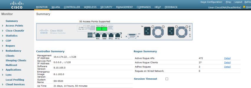
Define the Network for Cisco DNA Application Assurance

Define the Network for Cisco DNA Application Assurance

Audience
   The audience for this document includes network design engineers and network operations personnel who wish to gain
   visibility into applications and the performance of those applications on their networks, through the use of Cisco DNA
   Application Assurance running within Cisco DNA Center.

Purpose of this Document
   This guide focuses on the following:

    •    How to enable / deploy Cisco DNA Application Assurance within an enterprise network.

    •    How to monitor and troubleshoot applications and application performance as traffic crosses the LAN & WAN, through
         the use of Cisco DNA Application Assurance.

Solution Overview
   The following figure shows the high-level network design for this deployment guide.

   Figure 2 High-level Network Design

   The Cisco DNA Center site hierarchy consists of a single campus and two branches. The WAN connectivity models were
   chosen to be consistent with common deployments seen within customer networks.

   The WAN Aggregation block within the campus consists of two Cisco ASR 1K routers (WE-ASR1002X-1 and WE-ASR1002X-3).

   WE-ASR1002X-1 connects to a service provider (SP) managed services network that provides four classes of service (SP 4-
   class model). The DSCP markings of traffic leaving the enterprise network are re-marked to one of the four traffic-classes

                                                              6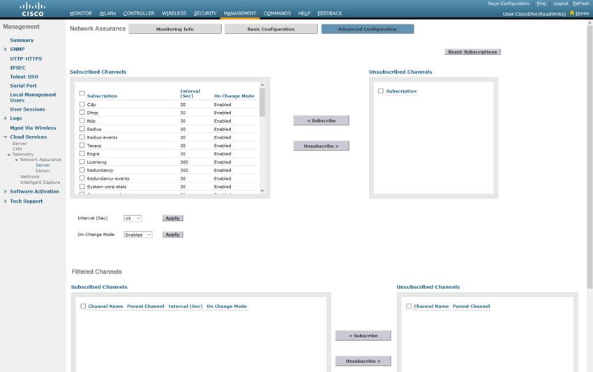
Define the Network for Cisco DNA Application Assurance

   supported by the SP network. Traffic entering the enterprise network from the SP is classified and re-marked to one of the
   12 traffic-classes supported by the enterprise network through an NBAR-based ingress classification & marking QoS policy.

   WE-ASR1002X-3 is connected to an Internet connection with the option of either DMVPN or IPsec protected GRE
   connectivity configuration. All traffic to-and-from WE-ASR1002X-3 is sent through either the DMVPN or IPsec protected GRE
   connection. Although traffic sent to and from the Internet is remarked to a default value (DSCP 0), the original DSCP
   markings of the enterprise traffic are preserved within the DMVPN / IPsec protected GRE tunnel between WE-ASR1002X-3
   and Branch 5.

   Branch 2 is connected through a service provider (SP) managed-services network which provides four classes of service (SP
   4-Class model). The DSCP markings of traffic leaving Branch 2 are re-marked to one of the four traffic-classes supported by
   the SP network. Traffic entering Branch 2 from the SP network is classified and re-marked to one of the 12 traffic-classes
   supported by the enterprise network through an NBAR-based ingress classification & marking QoS policy.

   Branch 5 is connected through an Internet connection with the option of either DMVPN or IPsec protected GRE connectivity
   configuration. All traffic between the campus and Branch 5 is sent through either the DMVPN or IPsec protected GRE
   connection. Although traffic sent to and from the Internet is remarked to a default value (DSCP 0), the original DSCP
   markings of the enterprise traffic are preserved within the DMVPN / IPsec protected GRE tunnel between the campus and
   Branch 5.

   The campus LAN distribution block consists of Catalyst 9000 Series switches configured as Layer 2 (L2) access switches,
   connected to a Layer 3 (L3) distribution switch. Wired traffic application visibility within the campus is accomplished
   through Flexible NetFlow flow monitors configured on the access-ports of the Catalyst 9000 access-layer switches.

   The wireless design consists of a single pair of AireOS 5520 wireless LAN controllers (WLCs) supporting Access Points (APs)
   operating in FlexConnect mode within the branches; and APs operating in centralized (local) mode within the campus.
   Wireless clients are connected to the APs within the branches and the campus. Within the branches, FlexConnect mode is
   necessary to terminate branch wireless traffic onto the branch LAN switches, rather than backhauling it within a CAPWAP
   tunnel. This allows for visibility into the wireless traffic flows between the campus and the branch locations, at the head-end
   routers. Access Points (APs) operating in centralized (local) mode are deployed within the campus. APs operating in
   centralized mode encapsulate and backhaul all traffic within a CAPWAP tunnel from the AP to the wireless LAN controller
   (WLC). In centralized mode, all wireless traffic application visibility is lost at the access-layer switches because of the
   CAPWAP encapsulation. Wireless traffic application visibility within the campus is accomplished through streaming
   telemetry at the AireOS WLCs.

        Technical Note: The implementation of the WAN, LAN, and WLAN deployment is not covered within this document.

Assumptions
   This deployment guide makes the following assumptions:

    •    The network shown above is already designed and deployed.

    •    The site hierarchy within Cisco DNA Center has been created.

    •    The network devices have already been discovered and assigned to their respective sites within Cisco DNA Center.

   The next section, Design the Network for Cisco DNA Application Assurance, will discuss the design decisions and
   implications regarding where to implement Cisco DNA Application Assurance within the network discussed above. Following
   that, the Deploy Cisco DNA Application Assurance on the Network section will discuss how to enable the collection of Cisco
   DNA Application Assurance data on the devices discussed within the design section. Finally, the Operate the Network
   section discusses multiple use cases regarding how Cisco DNA Application Assurance can be used to identify applications on
   the network and to assist in identifying and troubleshooting application performance issues.

                                                               7
Design the Network for Cisco DNA Application Assurance

Design the Network for Cisco DNA Application Assurance
   As of Cisco DNA Center release 1.3.1, Cisco DNA Application Assurance has been expanded to collect application visibility
   data on Catalyst 9000 Series switches and AireOS WLCs. As a result of this, Cisco DNA Application Assurance now supports
   the following two different types of data collection, depending upon the platform deployed within the network.

    •    Application experience data

    •    Application visibility data

   The following table summarizes the differences in the data collected and displayed within Cisco DNA Center depending upon
   whether the platform supports application experience data collection or application visibility data collection.

   Table 1     Data Collected / Displayed by Application Experience & Application Visibility
     Per-application data collected and/or displayed        Collected through application             Collected through
     in Cisco DNA Center                                    experience?                               application visibility?
     Application name                                       Yes                                       Yes

     Usage and throughput statistics                        Yes                                       Yes

     Traffic-class                                          Yes                                       Yes

     Performance metrics (latency, jitter, packet loss)     Yes, for certain flows (TCP, RTP, etc.)   No

     Health scores (based on performance metrics)           Yes                                       No

     QoS (DSCP) markings of traffic flows                   Yes                                       No

        Technical Note: The traffic-class for applications displayed within Cisco DNA Center is derived from the application
                name, and the mapping of the application name to the NBAR traffic-class attribute setting for that application
                within Cisco DNA Center. Likewise health scores are derived from the performance metrics for each
                application.

   The following table summarizes the platforms which support the collection of the two types of Cisco Application Assurance
   data.

   Table 2     Cisco Platform Support for Application Experience versus Application Visibility in Cisco DNA Center
     Platform                          Data Collection               Notes
     Cisco IOS-XE routers              Application experience        Requires IOS XE 16.x and higher with active NBAR2 license
                                       data collection

     Catalyst 9000 Series switches     Application visibility data   Requires Cisco DNA Advantage license
                                       collection
     (Not including Catalyst 9600
     or 9500 switches)

     Cisco AireOS WLCs                 Application visibility data   AireOS version 8.8.114.130 and higher, except AireOS 8.9.x
                                       collection                    does not support Application Visibility

   This section of the design and deployment guide presents a high-level discussion of the underlying technology behind how
   Cisco DNA Application Assurance data is collected on the various platforms listed in Table 2. This information is necessary to
   understand the design decisions which need to be made regarding where to enable Cisco DNA Application Assurance within
   the network – and the implications of those decisions. An understanding of how Cisco DNA Application Assurance data is
   collected is also beneficial in interpreting the application information displayed within Cisco DNA Center.

                                                                        8
Design the Network for Cisco DNA Application Assurance

Cisco IOS-XE Router Platforms – Application Experience Data
   Application experience data is collected through Cisco Performance Monitor (PerfMon). Specifically, a Cisco Easy
   Performance Monitor (Cisco ezPM) policy context that uses the Application Performance profile is deployed on Cisco IOS XE
   router platforms. A profile is a pre-defined set of traffic monitors that can be enabled or disabled for a given context. The
   context itself is then applied to one or more interfaces on the Cisco IOS XE router platforms. Cisco ezPM provides an
   “express” method of implementing Cisco PerfMon, requiring minimal configuration.

        Technical Note: For more information regarding Cisco ezPM, as well as the available profiles and traffic monitors, please
                refer to the Easy Performance Monitor (ezPM) section of the Cisco Application Visibility and Control User
                Guide, located at the following URL:
                https://www.cisco.com/c/en/us/td/docs/ios/solutions_docs/avc/guide/avc-user-guide/avc_config.html#55042

   As of Cisco DNA Center release 1.3.1, Cisco Application Assurance deploys the Cisco ezPM Application Performance profile
   context only to Cisco router platforms running Cisco IOS XE 16.x software versions. Therefore, in a typical network, Cisco
   DNA Application Assurance is only capable of collecting application experience data for applications as the traffic crosses the
   WAN.

   The following are additional restrictions for deployment of the Cisco ezPM Application Performance profile context, specific
   to Cisco DNA Center:

    •    The interface to which the Cisco ezPM Application Performance profile context is applied must be a routed (Layer 3)
         interface with an IP address configured. Cisco DNA Center will not apply the context to a main interface if the
         interface does not have an IP address configured. For example, if the main interface on the router supports sub-
         interfaces that have IP addresses configured, then the main interface will not have an IP address configured. In this
         configuration, Cisco DNA Center will not apply the Cisco ezPM Application Performance profile context to the main
         interface.

    •    The interface to which the Cisco ezPM Application Performance profile context is applied must not be a sub-interface.
         For example, if the main interface on the router supports sub-interfaces, and each sub-interface has an IP address
         configured, Cisco DNA Center will not apply the Cisco ezPM Application Performance profile context to the sub-
         interfaces.

    •    Cisco DNA Center will not apply the Cisco ezPM Application Performance profile context to logical interfaces on the
         router platform. Interfaces such as port-channel interfaces and tunnel interfaces are not supported by Cisco DNA
         Center. Only physical Ethernet interfaces are supported by Cisco DNA Center.

   Cisco PerfMon uses the Cisco Network Based Application Recognition – Version 2 (NBAR2) engine within Cisco IOS XE to
   classify application traffic. Cisco NBAR2 releases are referred to as protocol packs. As of the current release (Protocol Pack
   46.0.0), Cisco NBAR2 can classify over 1400 applications. The following is the link to the Cisco NBAR2 protocol library:

   https://www.cisco.com/c/en/us/td/docs/ios-xml/ios/qos_nbar/prot_lib/config_library/nbar-prot-pack-library.html

   Each of the 1400+ applications known to the Cisco NBAR2 taxonomy have multiple attributes. From a Cisco DNA Application
   Assurance perspective two of the more important attributes are traffic-class and business relevance. For each application,
   the Cisco NBAR2 taxonomy has a default setting for whether the application is considered Business Relevant, Business
   Irrelevant, or Default. The meanings of each of these three business relevance categories is as follows:

    •    Business Relevant –Applications which directly support the business objectives of your organization. These
         applications should be classified, marked, and treated according to industry-standard best practice recommendations.
         Examples may include network management applications, voice and video applications, etc., depending on your
         organization.

                                                                9
Design the Network for Cisco DNA Application Assurance

     •    Business Irrelevant – Applications which do not support the business objectives of your organization. Applications of
          this type should be treated with a less than best effort service. Examples of these applications could include gaming
          applications, etc. depending on your organization.

     •    Default - Traffic from applications which may or may not be relevant to the operations of your organization. For
          example, some generic web traffic (HTTP or HTTPS) – perhaps for internal web-based applications – may be relevant to
          the operations of your organization; while other web traffic – perhaps for browsing the Internet – may not be relevant
          to the operations of your organization. Such traffic may be treated with a default per hop behavior (DSCP marking)
          across your network.

    Likewise, for each application, the Cisco NBAR2 taxonomy has a default setting for the traffic-class to which the application
    belongs. The traffic-class to which the application belongs determines its QoS treatment across the network – based upon
    the Cisco RFC 4594-based 12-class QoS model, shown in the following figure.

    Figure 3 Cisco RFC 4594-based 12-class QoS model

    Note that both the traffic-class and business relevance to which a particular application belongs can be modified through a
    QoS policy applied through Cisco DNA Center Application Policy. This is outside the scope of this document.

Where to Enable Cisco DNA Application Assurance on Cisco IOS-XE Router Platforms?
    Cisco DNA Application Assurance can be used to view information regarding application traffic – only as the traffic crosses an
    observation point at which Cisco DNA Application Assurance data is being collected. For application experience data,
    observation points are the interfaces on the Cisco IOS XE routers to which the Cisco ezPM Application Performance profile
    context is applied.

    When deciding to deploy Cisco DNA Assurance on Cisco router platforms, the first question that needs to be answered is
    what interface (or interfaces) on the Cisco IOS XE router platforms will serve as the application experience data observation
    points – based on the required use cases. The following sections discuss various options.

WAN Interfaces Connected to Managed-Services Networks
    Traffic sent across a managed-services network, such as an MPLS network, may or may not be encapsulated and/or
    encrypted – depending upon the business requirements of the particular deployment.

    If a tunneling protocol such as GRE is used to encapsulate all traffic (which may then be protected by IPsec), all application
    traffic entering / exiting the managed-services network will appear as GRE traffic. Visibility into the actual application traffic
    will be lost at the WAN-facing interface.

                                                                 10
Design the Network for Cisco DNA Application Assurance
If application traffic is not encapsulated within GRE (which may then be protected by IPsec), then application traffic entering
/ exiting the managed-services network may be visible at the WAN-facing interface.
WAN Interfaces Connected to the Internet
If a tunneling protocol such as GRE is used to encapsulate all traffic (which may then be protected by IPsec), then all
application traffic entering / exiting the Internet provider will appear as GRE traffic. Visibility into the actual application
traffic will be lost at the WAN-facing interface.
From a Cisco DNA Center Application Assurance perspective, if the WAN-facing interface of a router were chosen as the
application experience data observation point on either the head-end ASR1K routers or the branch routers, and if GRE
encapsulation is used (which may then be protected by IPsec); all traffic appears as GRE, and visibility into the actual
applications is lost. Hence, this design would not work for the use case of gaining visibility into the applications on the
enterprise network.
LAN-Facing Interfaces
From a Cisco DNA Application Assurance perspective, when DMVPN or IPsec protected GRE tunnels are implemented on
routers, application traffic is only encapsulated / decapsulated within GRE tunnels as the traffic is sent over the WAN.
Therefore, enabling the observation points on the LAN-facing interfaces will work for the use case of gaining visibility into
the applications on the enterprise network – at least for applications where traffic crosses the WAN between the campus
and branch locations.
Head-end vs. Branch Routers
When deciding to deploy Cisco DNA Assurance, the next question that needs to be answered is what Cisco router platforms
will serve as the application experience data observation points for Cisco DNA Application Assurance – based on the
required use cases. The following are the choices:
• Branch routers
• Head-end routers
• Both the head-end and branch routers
Although the first impulse may be to simply enable application experience data observation points everywhere – with the
thought that more visibility is better, some thought has to go into this decision – again based on the required use cases. The
following sections discuss various options.
Branch Routers
Enabling application experience data observation points on the LAN-facing interfaces of each branch router will provide
visibility into application traffic from the campus to each branch – but only if the traffic enters or exits one or more LAN-
facing interfaces of the branch router. Traffic from data center management servers destined for interfaces such as
Loopback0 on the branch router may not be visible, since the management traffic does not cross the observation point.
Application traffic between different subnets within the branch may be visible, but only if the subnets are terminated on
separate interfaces on the branch router. The interface to which the Cisco ezPM Application Performance profile context is
applied cannot not be a sub-interface. For example, if the main interface on the router supports sub-interfaces, and each
sub-interface has an IP address configured, Cisco DNA Center will not apply the Cisco ezPM Application Performance profile
context to the sub-interfaces.
Application flows between different branches will be visible. However, these flows will be double counted – once on each
branch observation point.
Application flows within the campus are not visible.
11Design the Network for Cisco DNA Application Assurance
If application experience data observation points are enabled within each branch router, the Cisco DNA Application
Assurance data must be backhauled across the WAN via Flexible NetFlow / IPFIX. This will consume some of the available
WAN bandwidth to each branch, depending upon the number of application flows seen, the amount of traffic per flow, etc.
Likewise, the scale of the deployment may be limited by the number of Flexible NetFlow / IPFIX export flows which can be
handled by Cisco DNA Center – since each branch will contribute at least one flow. Finally, enabling Cisco PerfMon (in the
form of Cisco ezPM) and backhauling the traffic via Flexible NetFlow / IPFIX will result in some performance impact of each
branch router. The specific impact depends on the router platform, Cisco IOS XE code revision, the number of application
flows seen, the amount of traffic per flow, etc.
Head-end Routers
Enabling application experience data observation points on the LAN-facing interfaces of WAN head-end routers will again
provide visibility into application traffic from the campus to each branch. Traffic from data center management servers
destined for interfaces such as Loopback0 on the branch router will be visible, since the observation point is on the head-end
router. Likewise, traffic from data center management servers destined for interfaces such as Loopback0 on the WAN head-
end routers will also be visible – since the traffic has to enter/exit the LAN-facing interface to reach the Loopback0 interface.
Application traffic between subnets within the branch will not be visible. This is because the application traffic flows do not
cross the application experience observation point at the WAN head-end router. Application traffic between branches
connected to the same head-end router will not be visible – since the application traffic flows never cross the application
experience data observation point at the LAN-facing interface of the WAN head-end router. Application traffic between
branches connected to different WAN head-end routers may or may not be visible – depending upon whether the
application traffic flows cross the application experience data observation points on the LAN-facing interfaces of the WAN
head-end routers. Further, these flows may be double-counted – once on each WAN head-end router observation point. In
other words, each WAN head-end router may display application statistics. However, the total amount of application traffic
may not simply be the sum of the application statistics on the routers, since some flows may be duplicated.
Application flows within the campus are not visible.
If application experience data observation points are enabled within each WAN head-end router, the Cisco DNA Application
Assurance data is only backhauled across the campus LAN via Flexible NetFlow / IPFIX. WAN bandwidth to each branch is
not consumed. This is a significant advantage, since WAN bandwidth generally is a recurring expense, versus LAN bandwidth
which can be increased relatively easily by increased interface speeds. Likewise, the scale of the deployment is not limited
by the number of Flexible NetFlow / IPFIX export flows which can be handled by Cisco DNA Center – since there are
relatively few WAN head-end routers, compared to branch routers.
However, since each WAN head-end router sees significantly more application flows – compared to individual branch
routers, the performance impact of enabling Cisco PerfMon (in the form of Cisco ezPM) and backhauling the traffic via
Flexible NetFlow / IPFIX to Cisco DNA Center, on the WAN head-end routers must be more carefully managed. Specifically,
the CPU utilization and throughput of the current WAN head-end routers must be sufficient to account for the extra load
when Cisco DNA Application Assurance is enabled.
Both Head-end and Branch Routers
The main advantage of enabling application experience data observation points on the LAN-facing interfaces of both branch
and WAN head-end routers, is that it provides more visibility into application flows between subnets within a single branch,
between branches, and between the campus and branches.
However, this benefit may be offset by duplication of flow data. For example, an application flow between two devices each
within a different branch, with each branch connected to a different WAN head-end router – may be counted four times.
This is because the flow may be seen at the application experience observation data point of the first branch, the application
experience data observation point of the first WAN head-end router, the application experience data observation point of
the second WAN head-end router, and the application experience data observation point of the second branch router. This
may skew application usage statistics presented by Cisco DNA Application Assurance.
12Design the Network for Cisco DNA Application Assurance
Application flows within the campus are not visible.
Finally, enabling application experience data observation points on both the head-end and branch routers is also limited by
the scalability of having at least one Flexible NetFlow / IPFIX export flow per branch terminating on Cisco DNA Center, as well
as the amount of bandwidth consumed on each branch due to the Flexible NetFlow / IPFIX flow data.
Cisco Catalyst 9000 Series Switch Platforms – Application Visibility Data
For Catalyst 9000 Series switches, application visibility data is collected through a wired AVC Flexible NetFlow (FNF) flow
monitor applied bi-directionally (ingress and egress) to switch ports. The flow record corresponding to the flow monitor,
includes the application name as a key value (a match statement as opposed to a collect statement). Inclusion of the
application name as a field within the wired AVC FNF record automatically enables NBAR2 for the interfaces to which the
flow monitor is applied.
Application visibility data collected by Cisco DNA Application Assurance on Catalyst 9000 Series switches complements the
application experience data collected on Cisco IOS XE routers by providing visibility into applications without the application
traffic having to cross a router interface – in other words without having to cross the WAN.
The following are additional restrictions for deployment of the wired AVC FNF flow monitor on Catalyst 9000 Series switches,
specific to Cisco DNA Center:
• The switch port to which the wired AVC FNF flow monitor is applied must be configured as an access port. Specifically
the command switch-mode access must be configured on the switch port. NBAR2 on Catalyst 9000 Series
switches is scaled (in terms of performance) primarily for access ports on access-layer switches.
• Cisco DNA Center will not apply the wired AVC FNF flow monitor to trunk ports.
• Cisco DNA Center will not apply the wired AVC FNF flow monitor to switch ports configured as Layer 3 (L3) routed
interfaces.
• Cisco DNA Center will not apply the wired AVC FNF flow monitor to logical interfaces such as port-channel interfaces,
loopback interfaces, etc.
Where to Enable Cisco DNA Application Assurance on Cisco Catalyst 9000 Series Switch Platforms?
As with IOS XE router platforms, Cisco DNA Application Assurance can be used to view information regarding application
traffic – but only as the traffic crosses an observation point at which Cisco DNA Application Assurance data is being collected.
For application visibility data on Catalyst 9000 Series switch platforms, observation points are the switch ports to which the
wired AVC FNF flow monitor is applied.
When deciding to deploy Cisco DNA Assurance on Catalyst 9000 Series switch platforms, a question that needs to be
answered is what switch will serve as the application visibility data observation points – based on the required use cases.
The following sections discuss various options.
Technical Note: SD-Access (fabric) deployments are not discussed within this deployment guide.
Uplink Ports on Access-layer Switches
For Catalyst 9000 Series switches deployed in the role of a traditional (non-fabric) Layer 2 (L2) access-switch, uplink ports are
often configured as trunk ports, which support the various VLANs configured across the access-ports (i.e. ports connected to
end-devices). As discussed in the additional restrictions above, Cisco DNA Center will not apply the wired AVC FNF Flow
monitor for collecting application visibility data to trunk ports.
Also, Layer 2 (L2) switch uplink ports are frequently configured for high-availability via an EtherChannel configuration. In
order to correctly classify certain applications, NBAR2 requires symmetric flows – meaning the application traffic must be
13Design the Network for Cisco DNA Application Assurance
sent and received by the same interface (logical or physical). Port-channel interfaces are used to provide a single logical
interface in such a configuration. However, Catalyst 9000 Series switches do not support the ability to configure wired AVC
FNF flow monitors on Layer 2 (L2) port-channel interfaces. Therefore, Cisco DNA Center will not apply the wired AVC FNF
flow monitor to logical interfaces, as discussed in the restrictions above.
For Catalyst 9000 Series switches deployed in the role of a traditional (non-fabric) Layer 3 (L3) access-switch or as a Cisco SD-
Access Fabric-Edge (FE) switch, uplink ports are configured as routed interfaces. Cisco DNA Center will not apply the wired
AVC FNF flow monitor for collecting application visibility data to routed interfaces.
Hence, the ability to collect application visibility data on uplink interfaces of access-layer switches is limited to the use case
of a traditional (non-fabric) Layer 2 switch with no EtherChannel and no trunk configuration – in other words the uplink port
configured as an access-port. Note however, that NBAR2 is scaled (in terms of performance) for access ports on access-layer
switches.
Access-ports on Access-layer Switches
Regardless of whether a Catalyst 9000 Series switch is configured as a traditional (non-fabric) L2 or L3 access switch, ports
connected to end-user devices are generally configured as access-ports. Cisco DNA Center will apply the wired AVC FNF flow
monitor to these interfaces.
Technical Note: The network administrator must still express his/her business intent to collect application visibility data
on each desired switch access-port by explicitly configuring the word lan within the interface description.
Also, the switch port must explicitly be configured with the switchport mode access command in order
for Cisco DNA Center to apply the wired AVC FNF flow monitor.
Therefore, application visibility deployed on access-ports of Catalyst 9000 Series access-layer switches will generally provide
visibility into application traffic generated by wired devices connected to the switch ports.
However, for switch ports connected to wireless Access Points (APs), visibility into application traffic may be limited. If the
wireless deployment is a centralized (local) mode deployment connected to a traditional (non-fabric) access-layer switch
port – all application traffic to and from the APs is encapsulated in CAPWAP headers. If the AP is part of a FlexConnect mode
wireless deployment connected to a traditional (non-fabric) access-layer switch port – the AP may be configured to support
multiple VLANs. Hence the switch port may be configured as a trunk port, and Cisco DNA center will not apply the wired
AVC FNF flow monitor to the switch port connected to the FlexConnect AP. Only when the FlexConnect AP is configured
with a single VLAN, meaning the switch port is configured as an access-port, will application visibility data on the Catalyst
9000 Series switch provide visibility to applications on the switch port.
Distribution and Core Layer Switches
As mentioned in the restrictions above, Cisco DNA Center will only apply the wired AVC FNF flow monitor for application
visibility data collection to Layer 2 (L2) access-ports on switches. Most distribution switches are generally configured for
Layer 3 routed interfaces connecting to either Layer 3 core and access-switches. Alternatively, distribution switches may be
configured with Layer 2 (L2) trunk interfaces connecting to Layer 2 access-switches – often in an EtherChannel configuration
with port-channel interfaces. In other words, typically switch ports on distribution switches are not configured as access-
ports, and therefore the wired AVC FNF flow monitor for application visibility may not be applied to such switch ports by
Cisco DNA Center.
Likewise, typically switch ports on core switches are typically not configured as Layer 2 (L2) access-ports either. Therefore,
the wired AVC FNF flow monitor for application visibility may not be applied to such switch ports by Cisco DNA center.
Again, note that NBAR2 is scaled (in terms of performance) for access ports on access-layer switches.
Technical Note: AVC / NBAR is not supported on Catalyst 9500 or Catalyst 9600 Series switches.
14Design the Network for Cisco DNA Application Assurance
Cisco AireOS WLC Platforms – Application Visibility Data
For Cisco AireOS WLCs, application visibility data is collected at the WLC and streamed via telemetry from the WLC to Cisco
DNA Center. Specifically, application visibility is collected through a subscription to the Client-app-stat-events network
assurance telemetry channel within the AireOS WLC.
Technical Note: Unlike Catalyst 9000 Series switches, wired AVC Flexible NetFlow (FNF) flow monitors are not
implemented for application visibility on Cisco AireOS WLCs.
Application visibility data collected by Cisco DNA Application Assurance on AireOS WLCs complements the application experience
data collected on Cisco IOS XE routers and the application visibility data collected on Cisco Catalyst 9000 Series switches – by
providing visibility into applications across the WLAN.
Technical Note: As of Cisco DNA Center release 1.3.1, application visibility data is only collected on Cisco AireOS WLCs.
Collection and display of application visibility data on Cisco Catalyst 9800 WLCs is targeted for a future release.
The following are additional restrictions for application visibility on Cisco AireOS WLCs:
• Application visibility data on AireOS WLCs is not available for APs operating in FlexConnect mode.
Technical Note: SD-Access fabric-enabled wireless (FEW) deployments are not discussed within this deployment guide.
Where to Enable Cisco DNA Application Assurance on Cisco AireOS WLC Platforms?
As with IOS XE router platforms and Catalyst 9000 Series switches, Cisco DNA Application Assurance can be used to view
information regarding application traffic – but only as the traffic crosses an observation point at which Cisco DNA Application
Assurance data is being collected. For application visibility data on Cisco AireOS WLC platforms, observation points are
essentially the APs to which the wireless clients are connected, although the application visibility data is sent from the
AireOS WLC platforms that are subscribed to the Client-app-stat-events network assurance telemetry channel.
Deployment Guide Implementation
Ultimately, it is a design decision of the network administrator as to where to enable collection of Cisco DNA Application
Assurance information to gain the desired visibility into application flows, while minimizing the collection of duplicate flows.
The following sections discuss the areas of the network where collection of Cisco DNA Application Assurance information
was done for this deployment guide.
Wide Area Network (WAN)
The Cisco ezPM Application Performance profile context was applied to the LAN-facing interfaces (GigabitEthernet0/0/0) of
the Cisco ASR 1K routers (WE-ASR1002X-1 and WE-ASR1002X-3) serving as the WAN head-end routers within the campus.
Application experience data is sent from the ASR 1K WAN head-end routers to Cisco DNA Center via Flexible NetFlow / IPFIX.
With this design, application flows between the campus and the branches are visible to Cisco DNA Center. This is highlighted
in the figure below.
15Design the Network for Cisco DNA Application Assurance
Figure 4 WAN Traffic Visibility through Cisco DNA Application Assurance for the Deployment Guide
The LAN-facing interfaces of the routers were chosen as observation points to ensure visibility of the application traffic
across the enterprise network. The WAN head-end routers were chosen to minimize the number of Flexible NetFlow / IPFIX
export flows which need to be handled by Cisco DNA Center and eliminate any bandwidth consumption due to exporting
Flexible NetFlow / IPFIX data across the WAN.
However, not all application flows are visible with this design. Application flows within individual branches are not seen.
Application flows between the two branches are seen, but only because each branch connects to a different head-end
router. Flow information is also duplicated since branch-to-branch flows in this deployment guide cross the observation
points of both head-end routers. Flows within the campus are not seen by the WAN head-end routers.
Finally, it should be noted that because Cisco DNA Center does not apply the Cisco ezPM Application Performance profile
context to logical interfaces, a logical port-channel interface between the ASR 1K head-end routers and WAN aggregation
switch was not implemented. Since NBAR2 requires symmetric routing – meaning return traffic must enter the same
interface as outbound traffic – in order to identify certain applications; equal cost multi-path (ECMP) routes were also not
used. A single routed uplink between each head-end ASR1K router ad the WAN aggregation switch was implemented for
this deployment guide.
Local Area Network (LAN)
The wired AVC FNF flow monitor was applied to the access-ports (i.e. ports connected to end-user devices) of Catalyst 9000
Series switches access-layer switches within Cisco DNA Center.
With this design, application flows from wired end-user devices connected to the campus switches is visible to Cisco DNA
Center. This is highlighted in the figure below.
16Design the Network for Cisco DNA Application Assurance
Figure 5 LAN Traffic Visibility through Cisco DNA Application Assurance for the Deployment Guide
Since APs within the campus are operating in centralized (local) mode within this deployment guide, all traffic appears as
either CAPWAP control or CAPWAP data traffic to the Catalyst 9000 Series switch ports. Therefore, although application
visibility was enabled on the Catalyst 9000 Series switch ports connected to APs within the campus for this deployment
guide, it provides limited value – other than displaying how much CAPWAP traffic is being generated by the APs connected
to the switches. Visibility into the application traffic of campus wireless device is instead provided through the AireOS WLC
itself.
Collection of application visibility data was not enabled for Catalyst 9000 Series distribution-layer or core switches within this
deployment guide.
Wireless Local Area Network (WLAN)
Wireless telemetry was enabled at the campus AireOS WLC HA pair (SS-5520) for this deployment guide. With this design,
application flows from wireless devices connected to APs within the campus are visible to Cisco DNA Center. This is
highlighted in the figure below.
17Design the Network for Cisco DNA Application Assurance
Figure 6 WLAN Traffic Visibility through Cisco DNA Application Assurance for the Deployment Guide
Since the APs within the branch are operating on FlexConnect mode, no application visibility data is provided through
wireless telemetry for wireless devices within the branch. Visibility into the application traffic of branch wireless devices is
instead provided through application experience data collected at the WAN head-end routers.
18Deploy Cisco DNA Application Assurance on the Network
Deploy Cisco DNA Application Assurance on the Network
Enabling Cisco DNA Application Assurance on the network consists of the following procedures.
• Configure the IOS XE router interfaces for Cisco DNA Application Assurance
• Configure the Catalyst 9000 Series switch ports for Cisco DNA Application Assurance
• Configure the AireOS WLCs for Cisco DNA Application Assurance
• Configure routers, Catalyst 9000 Series switches, and AireOS WLCs for Maximal Telemetry within Cisco DNA Center
Procedure: Configure the IOS XE Router Interfaces for Cisco DNA Application Assurance
In order to specify the IOS XE router platform interfaces to which you wish to apply the Cisco ezPM Application Performance
profile context, you must add the following tag to the interface description:
lan
For this design and deployment guide, Cisco DNA Application Assurance data is collected from the GigabitEthernet0/0/0
interfaces of both WAN ASR1K head-end routers – WE-ASR1002X-1 and WE-ASR1002X-3.
The following are the steps to configure an IOS XE router interface to collect Cisco DNA Application Assurance data.
1. SSH to the IOS XE router platform to which you wish to enable collection of Cisco DNA Application Assurance data.
2. Specify the necessary login credentials (userid/password or certificates).
3. Specify enable mode on the IOS XE router platform if necessary, by entering the exec-level command enable and
pressing enter.
Technical Note: If the userid that you use to SSH into the platform has a privilege level of 15, you will automatically be
taken into enable mode.
4. Enter configuration mode on the IOS XE router by entering the exec-level command configuration terminal and
pressing enter.
5. Specify the interface which you wish receive Cisco DNA Application Assurance data. Press enter to go to the
interface-level configuration.
For this deployment guide the command is interface GigabitEthernet 0/0/0.
6. Add the lan tag to the interface description.
For this deployment guide the command is description lan Link to WA-6880-VSS. Note that the tag only needs to appear
within the description – it does not need to replace the description.
7. Exit interface-level configuration mode by typing the configuration-level command exit and pressing enter.
8. Exit configuration mode by typing the configuration-level command exit and pressing enter.
9. Save the running-configuration change to the startup-configuration by typing the exec-level command copy
running-config startup-config.
10. Press enter to confirm the destination filename of startup-config.
19Deploy Cisco DNA Application Assurance on the Network
11. Exit the router by typing the exec-level command exit and pressing enter.
The following example illustrates the steps above regarding how to specify that you want Cisco DNA Center to collect Cisco
DNA Application Assurance data from the GigabitEthernet0/0/0 interface of the WE-ASR1002X-1 router platform with an IP
address of 10.4.32.241. Note that the userid has been modified within the example.
userid@host:~$ ssh userid@10.4.32.241
Password:
WE-ASR1002X-1#configure terminal
Enter configuration commands, one per line. End with CNTL/Z.
WE-ASR1002X-1(config)#interface GigabitEthernet 0/0/0
WE-ASR1002X-1(config-if)#description lan Link to WA-6880-VSS
WE-ASR1002X-1(config-if)#exit
WE-ASR1002X-1(config)#exit
WE-ASR1002X-1#copy running-config startup-config
Destination filename [startup-config]?
Building configuration...
[OK]
WE-ASR1002X-1#exit
Connection to 10.4.32.241 closed by remote host.
Connection to 10.4.32.241 closed.
userid@host:~$
12. Repeat Steps 1- 11 for the second head-end router, WE-ASR1002X-3.
When you are complete both GigabitEthenet0/0/0 interface descriptions should look as follows:
WE-ASR1002X-1
interface GigabitEthernet0/0/0
description lan Link to WA-6880-VSS
ip address 10.4.32.2 255.255.255.252
WE-ASR1002X-3
interface GigabitEthernet0/0/0
description lan Link to WA-6880-VSS
ip address 10.4.32.10 255.255.255.252
You should make sure Cisco DNA Center is synced with the configuration changes of the previous procedure before enabling
Maximal Visibility within the Network Telemetry dashboard. You can wait until the inventory resync interval for the two
ASR 1K WAN head-end routers (WE-ASR1002X-1 and WE-ASR1002X-3) passes. Alternatively, you can manually resync the
inventory for the two ASR 1K WAN head-end routers using the following steps.
13. Login to the Cisco DNA Center web console using the IP address or fully qualified domain name of your instance.
For example: https://. The credentials (userid and password) you enter must have
SUPER-ADMIN-ROLE OR NETWORK-ADMIN-ROLE privileges.
14. From the main Cisco DNA Center dashboard, navigate to Provision.
This will take you to the main provisioning screen that displays the devices within the inventory. By default, the Focus: will
be set for Inventory.
15. Locate and check the boxes next to WE-ASR1002X-1 and WE-ASR1002X-3.
20Deploy Cisco DNA Application Assurance on the Network
16. From the drop-down menu under Actions, select Inventory > Resync Device.
A pop-up warning will ask you to confirm the resync.
17. Select OK to confirm the resync and close the warning.
The last sync status of WE-ASR1002X-1 and WE-ASR1002X-3 will transition to In Progress. After a few moments the last
sync status will transition back to Managed.
Once the two head-end routers are resynced, you can proceed to enable Maximal Visibility for the devices within the
Network Telemetry dashboard.
Procedure: Configure the Catalyst 9000 Series switch ports for Cisco DNA Application Assurance
In order to specify the Catalyst 9000 Series switch ports to which you wish to apply the wired AVC FNF flow monitor, you
must add the following tag to the switch port description:
lan
In addition to this, you must ensure that the switch port is explicitly configure as an access-port through the following
interface-level command:
switchport mode access
For this design and deployment guide, Cisco DNA Application Assurance data is collected on the following Catalyst 9000
Series switch ports:
• AD2-9200 - GigabitEthernet1/0/1 – GigabitEthernet 1/0/24
• AD2-9300 – GigabitEthernet1/0/1 – GigabitEthernet 1/0/48 and GigabitEthernet2/0/1 – GigabitEthernet 2/0/48
• AD2-9400 – GigabitEthernet1/0/1 – GigabitEthernet 1/0/48, GigabitEthernet2/0/1 – GigabitEthernet 2/0/48, and
GigabitEthernet5/0/1 – GigabitEthernet 5/0/24
The following are the steps to configure a range of Catalyst 9000 Series switch ports to collect Cisco DNA Application
Assurance data.
1. SSH to the Catalyst 9000 Series switch platform to which you wish to enable collection of Cisco DNA Application
Assurance data.
2. Specify the necessary login credentials (userid/password or certificates).
3. Specify enable mode on the router platform if necessary, by entering the exec-level command enable and pressing
enter.
Technical Note: If the userid that you use to SSH into the platform has a privilege level of 15, you will automatically be
taken into enable mode.
4. Enter configuration mode on the router by entering the exec-level command configuration terminal and pressing
enter.
5. Specify the switch port range which you wish receive Cisco DNA Application Assurance data. Press enter to go to
the interface-level configuration.
For the AD2-9200 switch within this deployment guide the command is interface range GigabitEthernet 0/0/0-24.
21You can also read