Galaxy 48 R CO 2 Incubator
←
→
Page content transcription
If your browser does not render page correctly, please read the page content below
R
gnual
  CO
EN)   Incubator
  manual
    2

                  Galaxy® 48 R CO2 Incubator

                  Operating manual
Copyright

Copyright © 2014 Eppendorf AG, Germany. No part of this publication may be reproduced without the
prior permission of the copyright owner.

The company reserves the right to change information in this document without notice. Updates to
information in this document reflect our commitment to continuing product development and
improvement.

Trademarks

Eppendorf® and the Eppendorf logo are registered trademarks of Eppendorf AG, Germany.

New Brunswick™ is a trademark of Eppendorf AG, Germany.

The New Brunswick™ logo is a trademark of Eppendorf, Inc., USA.

BioCommand® is a registered trademark of Eppendorf, Inc., USA.

Galaxy® is a registered trademark of Eppendorf, Inc., USA.

Microsoft® and Excel® are either registered trademarks or trademarks of Microsoft Corporation in the
United States and/or other countries.

Windows® is a registered trademark of Microsoft Corporation in the United States and other countries.

Trademarks are not marked in all cases with ™ or ® in this manual.

Eppendorf has attempted to identify the ownership of all trademarks from public records. Any omissions or
errors are unintentional.

6705 900.033-00-/032014
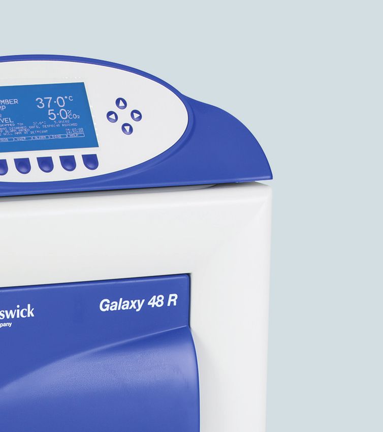
Table of contents
                                                                                                                      Galaxy® 48 R CO2 Incubator                     3
                                                                                                                                    English (EN)

Table of contents
1   Operating instructions . . . . . . . . . . . . . . . . . . . . . . . . . . . . . . . . . . . . . . . . . . . . . . . . . . . . . . . . . . . . . . 7
    1.1  Using this manual . . . . . . . . . . . . . . . . . . . . . . . . . . . . . . . . . . . . . . . . . . . . . . . . . . . . . . . . . . . . . 7
    1.2  Danger symbols and danger levels . . . . . . . . . . . . . . . . . . . . . . . . . . . . . . . . . . . . . . . . . . . . . . . . 7
         1.2.1    Hazard symbols. . . . . . . . . . . . . . . . . . . . . . . . . . . . . . . . . . . . . . . . . . . . . . . . . . . . . . . . 7
         1.2.2    Degrees of danger. . . . . . . . . . . . . . . . . . . . . . . . . . . . . . . . . . . . . . . . . . . . . . . . . . . . . . 7
    1.3  Symbols used . . . . . . . . . . . . . . . . . . . . . . . . . . . . . . . . . . . . . . . . . . . . . . . . . . . . . . . . . . . . . . . . 8

2   Product description . . . . . . . . . . . . . . . . . . . . . . . . . . . . . . . . . . . . . . . . . . . . . . . . . . . . . . . . . . . . . . . . 9
    2.1  Main illustration . . . . . . . . . . . . . . . . . . . . . . . . . . . . . . . . . . . . . . . . . . . . . . . . . . . . . . . . . . . . . . 9
    2.2  Control panel. . . . . . . . . . . . . . . . . . . . . . . . . . . . . . . . . . . . . . . . . . . . . . . . . . . . . . . . . . . . . . . . 10
    2.3  Accessories provided . . . . . . . . . . . . . . . . . . . . . . . . . . . . . . . . . . . . . . . . . . . . . . . . . . . . . . . . . 10
    2.4  Features. . . . . . . . . . . . . . . . . . . . . . . . . . . . . . . . . . . . . . . . . . . . . . . . . . . . . . . . . . . . . . . . . . . . 11
         2.4.1    Operating controls . . . . . . . . . . . . . . . . . . . . . . . . . . . . . . . . . . . . . . . . . . . . . . . . . . . . 11
         2.4.2    Direct heating system . . . . . . . . . . . . . . . . . . . . . . . . . . . . . . . . . . . . . . . . . . . . . . . . . . 11
         2.4.3    Infrared sensor . . . . . . . . . . . . . . . . . . . . . . . . . . . . . . . . . . . . . . . . . . . . . . . . . . . . . . . 11
         2.4.4    Controlled humidity tray . . . . . . . . . . . . . . . . . . . . . . . . . . . . . . . . . . . . . . . . . . . . . . . . 12
         2.4.5    Seamless chamber . . . . . . . . . . . . . . . . . . . . . . . . . . . . . . . . . . . . . . . . . . . . . . . . . . . . 12
         2.4.6    Multiple options . . . . . . . . . . . . . . . . . . . . . . . . . . . . . . . . . . . . . . . . . . . . . . . . . . . . . . 12
    2.5  Stacking devices . . . . . . . . . . . . . . . . . . . . . . . . . . . . . . . . . . . . . . . . . . . . . . . . . . . . . . . . . . . . . 12

3   Safety. . . . . . . . . . . . . . . . . . . . . . . . . . . . . . . . . . . . . . . . . . . . . . . . . . . . . . . . . . . . . . . . . . . . . . . . . . . 13
    3.1   Intended use . . . . . . . . . . . . . . . . . . . . . . . . . . . . . . . . . . . . . . . . . . . . . . . . . . . . . . . . . . . . . . . . 13
    3.2   User profile . . . . . . . . . . . . . . . . . . . . . . . . . . . . . . . . . . . . . . . . . . . . . . . . . . . . . . . . . . . . . . . . . 13
    3.3   Application limits . . . . . . . . . . . . . . . . . . . . . . . . . . . . . . . . . . . . . . . . . . . . . . . . . . . . . . . . . . . . 13
          3.3.1         Description of ATEX Guideline (94/9EC) . . . . . . . . . . . . . . . . . . . . . . . . . . . . . . . . . . . 13
    3.4   Information on product liability . . . . . . . . . . . . . . . . . . . . . . . . . . . . . . . . . . . . . . . . . . . . . . . . . 14
    3.5   Warnings for intended use . . . . . . . . . . . . . . . . . . . . . . . . . . . . . . . . . . . . . . . . . . . . . . . . . . . . . 14
          3.5.1         Personal injury and damage to device . . . . . . . . . . . . . . . . . . . . . . . . . . . . . . . . . . . . . 14

4   Installation . . . . . . . . . . . . . . . . . . . . . . . . . . . . . . . . . . . . . . . . . . . . . . . . . . . . . . . . . . . . . . . . . . . . . . 17
    4.1    Utilities requirements . . . . . . . . . . . . . . . . . . . . . . . . . . . . . . . . . . . . . . . . . . . . . . . . . . . . . . . . . 17
    4.2    Selecting the location . . . . . . . . . . . . . . . . . . . . . . . . . . . . . . . . . . . . . . . . . . . . . . . . . . . . . . . . . 17
    4.3    Initial setup . . . . . . . . . . . . . . . . . . . . . . . . . . . . . . . . . . . . . . . . . . . . . . . . . . . . . . . . . . . . . . . . . 18
           4.3.1     Installing the feet . . . . . . . . . . . . . . . . . . . . . . . . . . . . . . . . . . . . . . . . . . . . . . . . . . . . . 18
           4.3.2     Setting up . . . . . . . . . . . . . . . . . . . . . . . . . . . . . . . . . . . . . . . . . . . . . . . . . . . . . . . . . . . 18

5   Operation . . . . . . . . . . . . . . . . . . . . . . . . . . . . . . . . . . . . . . . . . . . . . . . . . . . . . . . . . . . . . . . . . . . . . . . 23
    5.1  Preparing for operation. . . . . . . . . . . . . . . . . . . . . . . . . . . . . . . . . . . . . . . . . . . . . . . . . . . . . . . . 23
    5.2  Using the humidity tray . . . . . . . . . . . . . . . . . . . . . . . . . . . . . . . . . . . . . . . . . . . . . . . . . . . . . . . 23
    5.3  Programming . . . . . . . . . . . . . . . . . . . . . . . . . . . . . . . . . . . . . . . . . . . . . . . . . . . . . . . . . . . . . . . 24
         5.3.1      Programming CO2, O2 and temperature . . . . . . . . . . . . . . . . . . . . . . . . . . . . . . . . . . . . 24
         5.3.2      User access code. . . . . . . . . . . . . . . . . . . . . . . . . . . . . . . . . . . . . . . . . . . . . . . . . . . . . . 24
         5.3.3      Removing user access code . . . . . . . . . . . . . . . . . . . . . . . . . . . . . . . . . . . . . . . . . . . . . 25
    5.4  Referencing the CO2 sensor with autozero. . . . . . . . . . . . . . . . . . . . . . . . . . . . . . . . . . . . . . . . . 25
    5.5  USER SETTINGS . . . . . . . . . . . . . . . . . . . . . . . . . . . . . . . . . . . . . . . . . . . . . . . . . . . . . . . . . . . . . 25
         5.5.1      SET DATE AND TIME . . . . . . . . . . . . . . . . . . . . . . . . . . . . . . . . . . . . . . . . . . . . . . . . . . 26
         5.5.2      AUDIBLE ALARM VOLUME ADJUST . . . . . . . . . . . . . . . . . . . . . . . . . . . . . . . . . . . . . . 26
         5.5.3      PROGRAMMABLE CO2 AUTOZERO . . . . . . . . . . . . . . . . . . . . . . . . . . . . . . . . . . . . . . 26
Table of contents
4   Galaxy® 48 R CO2 Incubator
    English (EN)

                 5.5.4   DATALOGGER. . . . . . . . . . . . . . . . . . . . . . . . . . . . . . . . . . . . . . . . . . . . . . . . . . . . . . . . 27
                 5.5.5   POWER FREQUENCY . . . . . . . . . . . . . . . . . . . . . . . . . . . . . . . . . . . . . . . . . . . . . . . . . . 27
                 5.5.6   DISABLE . . . . . . . . . . . . . . . . . . . . . . . . . . . . . . . . . . . . . . . . . . . . . . . . . . . . . . . . . . . . 28
                 5.5.7   DISINFECTION (optional) . . . . . . . . . . . . . . . . . . . . . . . . . . . . . . . . . . . . . . . . . . . . . . . 28
        5.6      DATALOGGER. . . . . . . . . . . . . . . . . . . . . . . . . . . . . . . . . . . . . . . . . . . . . . . . . . . . . . . . . . . . . . . 28
                 5.6.1   ALARM EVENTS . . . . . . . . . . . . . . . . . . . . . . . . . . . . . . . . . . . . . . . . . . . . . . . . . . . . . . 29
                 5.6.2   TEMPERATURE GRAPH + DOOR OPEN BAR CHART . . . . . . . . . . . . . . . . . . . . . . . . . 29
                 5.6.3   CO2 GRAPH + DOOR OPEN BAR CHART. . . . . . . . . . . . . . . . . . . . . . . . . . . . . . . . . . . 30
                 5.6.4   DIAGNOSTIC CHAMBER ELEMENT GRAPH . . . . . . . . . . . . . . . . . . . . . . . . . . . . . . . . 31
                 5.6.5   DIAGNOSTIC DOOR GRAPH. . . . . . . . . . . . . . . . . . . . . . . . . . . . . . . . . . . . . . . . . . . . . 31
                 5.6.6   DIAGNOSTIC DOOR ELEMENT GRAPH. . . . . . . . . . . . . . . . . . . . . . . . . . . . . . . . . . . . 31
                 5.6.7   RESTART GRAPHIC RECORD. . . . . . . . . . . . . . . . . . . . . . . . . . . . . . . . . . . . . . . . . . . . 31
        5.7      CHAMBER ALARMS . . . . . . . . . . . . . . . . . . . . . . . . . . . . . . . . . . . . . . . . . . . . . . . . . . . . . . . . . . 31
                 5.7.1   Arm chamber alarms after selectable delay . . . . . . . . . . . . . . . . . . . . . . . . . . . . . . . . . 32
                 5.7.2   Arm chamber alarms after setpoints are achieved . . . . . . . . . . . . . . . . . . . . . . . . . . . . 32
                 5.7.3   Door open alarm . . . . . . . . . . . . . . . . . . . . . . . . . . . . . . . . . . . . . . . . . . . . . . . . . . . . . . 32
                 5.7.4   Audible and visual alarms . . . . . . . . . . . . . . . . . . . . . . . . . . . . . . . . . . . . . . . . . . . . . . . 32
                 5.7.5   Chamber alarm system function . . . . . . . . . . . . . . . . . . . . . . . . . . . . . . . . . . . . . . . . . . 32
        5.8      DIAGNOSTICS menu screen . . . . . . . . . . . . . . . . . . . . . . . . . . . . . . . . . . . . . . . . . . . . . . . . . . . . 34
        5.9      HELP MENU screen . . . . . . . . . . . . . . . . . . . . . . . . . . . . . . . . . . . . . . . . . . . . . . . . . . . . . . . . . . 35
        5.10     High temperature disinfection . . . . . . . . . . . . . . . . . . . . . . . . . . . . . . . . . . . . . . . . . . . . . . . . . . 35
                 5.10.1 Using the high temperature disinfection . . . . . . . . . . . . . . . . . . . . . . . . . . . . . . . . . . . 35
                 5.10.2 High temperature disinfection option with oxygen control . . . . . . . . . . . . . . . . . . . . . 37
        5.11     Oxygen sensor removal. . . . . . . . . . . . . . . . . . . . . . . . . . . . . . . . . . . . . . . . . . . . . . . . . . . . . . . . 38
        5.12     BMS relay contact alarm. . . . . . . . . . . . . . . . . . . . . . . . . . . . . . . . . . . . . . . . . . . . . . . . . . . . . . . 38
        5.13     O2 control . . . . . . . . . . . . . . . . . . . . . . . . . . . . . . . . . . . . . . . . . . . . . . . . . . . . . . . . . . . . . . . . . . 40
                 5.13.1 Setting up the N2 tank. . . . . . . . . . . . . . . . . . . . . . . . . . . . . . . . . . . . . . . . . . . . . . . . . . 40
                 5.13.2 Setting up oxygen control (0.1 – 19 %) . . . . . . . . . . . . . . . . . . . . . . . . . . . . . . . . . . . . 40
                 5.13.3 Setting up oxygen control (1 – 19 %). . . . . . . . . . . . . . . . . . . . . . . . . . . . . . . . . . . . . . 41
                 5.13.4 Setting up oxygen control (1 – 95 %). . . . . . . . . . . . . . . . . . . . . . . . . . . . . . . . . . . . . . 43
        5.14     Referencing to atmosphere . . . . . . . . . . . . . . . . . . . . . . . . . . . . . . . . . . . . . . . . . . . . . . . . . . . . . 44
        5.15     Oxygen sensor replacement . . . . . . . . . . . . . . . . . . . . . . . . . . . . . . . . . . . . . . . . . . . . . . . . . . . . 45
                 5.15.1 Replace sensor soon . . . . . . . . . . . . . . . . . . . . . . . . . . . . . . . . . . . . . . . . . . . . . . . . . . . 45
                 5.15.2 Replace sensor now . . . . . . . . . . . . . . . . . . . . . . . . . . . . . . . . . . . . . . . . . . . . . . . . . . . 45
                 5.15.3 Removing and replacing O2 sensor. . . . . . . . . . . . . . . . . . . . . . . . . . . . . . . . . . . . . . . . 46
        5.16     Replacing the filter disc . . . . . . . . . . . . . . . . . . . . . . . . . . . . . . . . . . . . . . . . . . . . . . . . . . . . . . . 48
        5.17     Humidity alert and monitoring package . . . . . . . . . . . . . . . . . . . . . . . . . . . . . . . . . . . . . . . . . . . 49
                 5.17.1 Humidity tray warning system . . . . . . . . . . . . . . . . . . . . . . . . . . . . . . . . . . . . . . . . . . . 49
                 5.17.2 Humidity display and alarm system . . . . . . . . . . . . . . . . . . . . . . . . . . . . . . . . . . . . . . . 50
        5.18     RS-232 interface . . . . . . . . . . . . . . . . . . . . . . . . . . . . . . . . . . . . . . . . . . . . . . . . . . . . . . . . . . . . . 51

    6   Troubleshooting . . . . . . . . . . . . . . . . . . . . . . . . . . . . . . . . . . . . . . . . . . . . . . . . . . . . . . . . . . . . . . . . . . 55
        6.1   O2 sensor. . . . . . . . . . . . . . . . . . . . . . . . . . . . . . . . . . . . . . . . . . . . . . . . . . . . . . . . . . . . . . . . . . . 55

    7   Maintenance . . . . . . . . . . . . . . . . . . . . . . . . . . . . . . . . . . . . . . . . . . . . . . . . . . . . . . . . . . . . . . . . . . . . . 57
        7.1  Routine maintenance . . . . . . . . . . . . . . . . . . . . . . . . . . . . . . . . . . . . . . . . . . . . . . . . . . . . . . . . . 57
             7.1.1    General . . . . . . . . . . . . . . . . . . . . . . . . . . . . . . . . . . . . . . . . . . . . . . . . . . . . . . . . . . . . . 57
             7.1.2    Daily checks . . . . . . . . . . . . . . . . . . . . . . . . . . . . . . . . . . . . . . . . . . . . . . . . . . . . . . . . . 57
             7.1.3    Weekly checks. . . . . . . . . . . . . . . . . . . . . . . . . . . . . . . . . . . . . . . . . . . . . . . . . . . . . . . . 57
             7.1.4    Monthly checks . . . . . . . . . . . . . . . . . . . . . . . . . . . . . . . . . . . . . . . . . . . . . . . . . . . . . . . 57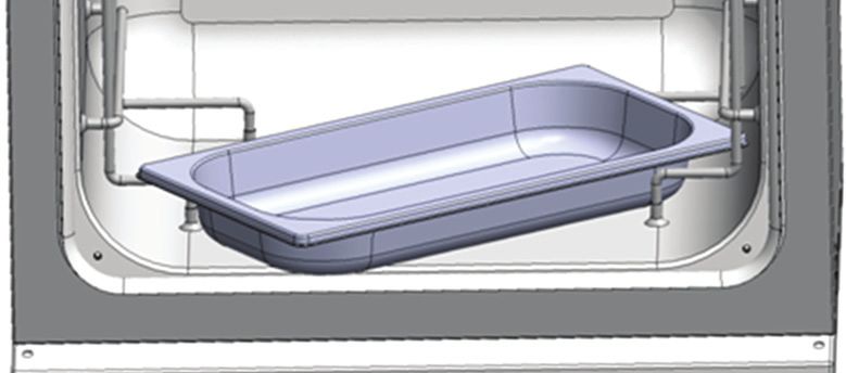
Table of contents
                                                                                                                       Galaxy® 48 R CO2 Incubator                     5
                                                                                                                                     English (EN)

               7.1.5    CO2 Sampling with analyzer . . . . . . . . . . . . . . . . . . . . . . . . . . . . . . . . . . . . . . . . . . . . . 58
     7.2       Cleaning . . . . . . . . . . . . . . . . . . . . . . . . . . . . . . . . . . . . . . . . . . . . . . . . . . . . . . . . . . . . . . . . . . . 58
     7.3       Disinfection/Decontamination. . . . . . . . . . . . . . . . . . . . . . . . . . . . . . . . . . . . . . . . . . . . . . . . . . . 59
     7.4       High temperature disinfection . . . . . . . . . . . . . . . . . . . . . . . . . . . . . . . . . . . . . . . . . . . . . . . . . . 60

8    Transport, storage and disposal . . . . . . . . . . . . . . . . . . . . . . . . . . . . . . . . . . . . . . . . . . . . . . . . . . . . . 61
     8.1   Transport. . . . . . . . . . . . . . . . . . . . . . . . . . . . . . . . . . . . . . . . . . . . . . . . . . . . . . . . . . . . . . . . . . . 61
     8.2   Disposal. . . . . . . . . . . . . . . . . . . . . . . . . . . . . . . . . . . . . . . . . . . . . . . . . . . . . . . . . . . . . . . . . . . . 61
     8.3   Storage . . . . . . . . . . . . . . . . . . . . . . . . . . . . . . . . . . . . . . . . . . . . . . . . . . . . . . . . . . . . . . . . . . . . 61

9    Technical data. . . . . . . . . . . . . . . . . . . . . . . . . . . . . . . . . . . . . . . . . . . . . . . . . . . . . . . . . . . . . . . . . . . . 63
     9.1  Weight/dimensions . . . . . . . . . . . . . . . . . . . . . . . . . . . . . . . . . . . . . . . . . . . . . . . . . . . . . . . . . . . 63
          9.1.1     Equipment dimensions . . . . . . . . . . . . . . . . . . . . . . . . . . . . . . . . . . . . . . . . . . . . . . . . . 63
          9.1.2     Internal dimensions. . . . . . . . . . . . . . . . . . . . . . . . . . . . . . . . . . . . . . . . . . . . . . . . . . . . 63
          9.1.3     Transporting dimensions . . . . . . . . . . . . . . . . . . . . . . . . . . . . . . . . . . . . . . . . . . . . . . . 63
          9.1.4     Shelves . . . . . . . . . . . . . . . . . . . . . . . . . . . . . . . . . . . . . . . . . . . . . . . . . . . . . . . . . . . . . 63
     9.2  Power supply. . . . . . . . . . . . . . . . . . . . . . . . . . . . . . . . . . . . . . . . . . . . . . . . . . . . . . . . . . . . . . . . 63
          9.2.1     Mains/electrical supply . . . . . . . . . . . . . . . . . . . . . . . . . . . . . . . . . . . . . . . . . . . . . . . . . 63
     9.3  Fuses . . . . . . . . . . . . . . . . . . . . . . . . . . . . . . . . . . . . . . . . . . . . . . . . . . . . . . . . . . . . . . . . . . . . . . 64
     9.4  Ambient conditions . . . . . . . . . . . . . . . . . . . . . . . . . . . . . . . . . . . . . . . . . . . . . . . . . . . . . . . . . . . 64
          9.4.1     Temperature management . . . . . . . . . . . . . . . . . . . . . . . . . . . . . . . . . . . . . . . . . . . . . . 64
          9.4.2     CO2 control . . . . . . . . . . . . . . . . . . . . . . . . . . . . . . . . . . . . . . . . . . . . . . . . . . . . . . . . . . 64
          9.4.3     Relative humidity . . . . . . . . . . . . . . . . . . . . . . . . . . . . . . . . . . . . . . . . . . . . . . . . . . . . . 64
          9.4.4     Altitude limit . . . . . . . . . . . . . . . . . . . . . . . . . . . . . . . . . . . . . . . . . . . . . . . . . . . . . . . . . 65
          9.4.5     Storage temperature . . . . . . . . . . . . . . . . . . . . . . . . . . . . . . . . . . . . . . . . . . . . . . . . . . . 65
     9.5  Oxygen sensor specifications . . . . . . . . . . . . . . . . . . . . . . . . . . . . . . . . . . . . . . . . . . . . . . . . . . . 65
     9.6  CO2 recovery . . . . . . . . . . . . . . . . . . . . . . . . . . . . . . . . . . . . . . . . . . . . . . . . . . . . . . . . . . . . . . . . 65

10 Ordering information . . . . . . . . . . . . . . . . . . . . . . . . . . . . . . . . . . . . . . . . . . . . . . . . . . . . . . . . . . . . . . 67
   10.1 Accessories . . . . . . . . . . . . . . . . . . . . . . . . . . . . . . . . . . . . . . . . . . . . . . . . . . . . . . . . . . . . . . . . . 67
   10.2 Available options . . . . . . . . . . . . . . . . . . . . . . . . . . . . . . . . . . . . . . . . . . . . . . . . . . . . . . . . . . . . . 67

11 Installation instructions for stacking stand kit. . . . . . . . . . . . . . . . . . . . . . . . . . . . . . . . . . . . . . . . . . 69
   11.1 Lower and upper stacking frame, with castors. . . . . . . . . . . . . . . . . . . . . . . . . . . . . . . . . . . . . . 69
          11.1.1 Base stand assembly instructions . . . . . . . . . . . . . . . . . . . . . . . . . . . . . . . . . . . . . . . . . 69
          11.1.2 Top stand bracket assembly instructions . . . . . . . . . . . . . . . . . . . . . . . . . . . . . . . . . . . 72
          11.1.3 Specifications . . . . . . . . . . . . . . . . . . . . . . . . . . . . . . . . . . . . . . . . . . . . . . . . . . . . . . . . 76

12 Declaration of conformity . . . . . . . . . . . . . . . . . . . . . . . . . . . . . . . . . . . . . . . . . . . . . . . . . . . . . . . . . . 77

     Index . . . . . . . . . . . . . . . . . . . . . . . . . . . . . . . . . . . . . . . . . . . . . . . . . . . . . . . . . . . . . . . . . . . . . . . . . . . 78
Table of contents
6   Galaxy® 48 R CO2 Incubator
    English (EN)
Operating instructions
Galaxy® 48 R CO2 Incubator 7
English (EN)
1 Operating instructions
1.1 Using this manual
Carefully read this operating manual before using the device for the first time.
Also observe the operating manual enclosed with the accessories.
The operating manual should be considered as part of the product and stored in a location that is easily
accessible.
When passing the device on to third parties, be sure to include this operating manual.
If this manual is lost, please request another one. The current version can be found on our website
www.eppendorf.com.
1.2 Danger symbols and danger levels
1.2.1 Hazard symbols
Hazard point Burns
Electric shock Material damage
Explosion Heavy loads
Inhalation Crush
1.2.2 Degrees of danger
The following degree levels are used in safety messages throughout this manual. Acquaint yourself with
each item and the potential risk if you disregard the safety message.
DANGER Will lead to severe injuries or death.
WARNING May lead to severe injuries or death.
CAUTION May lead to light to moderate injuries.
NOTICE May lead to material damage.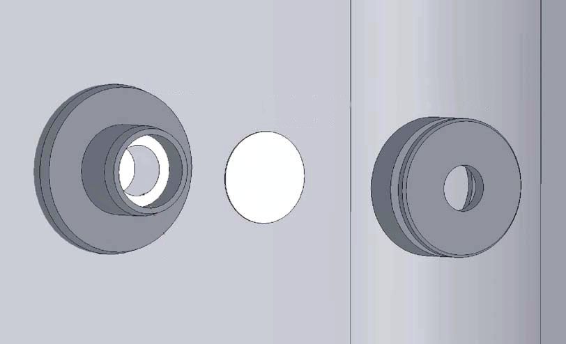
Operating instructions
8 Galaxy® 48 R CO2 Incubator
English (EN)
1.3 Symbols used
Example Meaning
You are requested to perform an action.
1. Perform these actions in the sequence described.
2.
• List.
References useful information.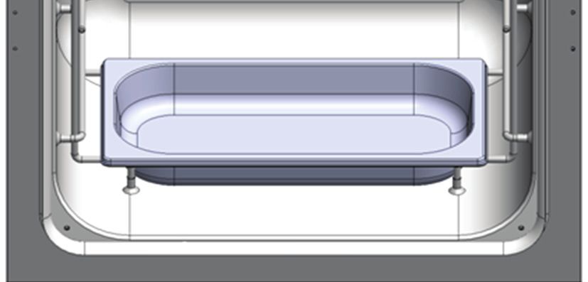
Product description
Galaxy® 48 R CO2 Incubator 9
English (EN)
2 Product description
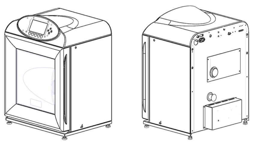
2.1 Main illustration
Abb. 2-1: Front and back view
1 2 3 4 5 6 7
13 12 11 10 9 8
Fig. 2-1: Front and back view
1 Operating controls 8 RS-232 connector
2 Sensor cover holder 9 N2 inlet (optional)
3 Main/power input 10 25 mm access port
4 CO2 inlet 11 Equipment tray
5 O2 inlet (optional) 12 O2 sensor port
6 CO2 sample port 13 Humidity control
7 Autozero filterProduct description
10 Galaxy® 48 R CO2 Incubator
English (EN)
2.2 Control panel
The control panel consists of an LCD display, 5 function keys and 4 direction keys.
Abb. 2-2: Control panel
1
2
Fig. 2-2: Control panel
1 Directional keys 2 Function keys
Move cursor around the screen Purpose of each key is identified at the bottom of
Adjust values the display (above the corresponding key)
Function may change from screen to screen
The HELP file contains most of the information in this operating manual, together with more
detailed troubleshooting information (see HELP MENU screen on p. 35).
2.3 Accessories provided
Tab. 2-1: Accessories
Quantity Item Notes
3 Non-tip shelves Installed
2 Wire shelf racks Installed
1 Humidity tray Packed separately
14 Silicone rubber suction feet Installed
Additional 4 spares packed in accessories bagProduct description
Galaxy® 48 R CO2 Incubator 11
English (EN)
Quantity Item Notes
1 White porous CO2 sensor cover Installed
Additional 2 spares packed in accessories bag
1 Black sensor cover Installed
1 Power cord Packed in accessories bag
3m PVC tubing, ~ 6mm (¼ in) bore, with an Packed in accessories bag
(9.8 ft) inline CO2 HEPA-filter connected, ready for
use
2 6 mm hoses for 02 0.1 % and 1 % options Supplied
3 6 mm hoses for 02 95 % option Supplied
2 Hose clips Packed in accessories bag
1 Autozero HEPA filter Packed in accessories bag
4 Adjustable feet Packed in accessories bag
4 Anti-slip pads for adjustable feet Packed in accessories bag
1 User manual Provided
2.4 Features
The Galaxy 48 R CO2 incubator is microprocessor-controlled and designed to ensure accurate and reliable
operation.
2.4.1 Operating controls
The incubator incorporates a sophisticated control system that allows for easy programming, control and
monitoring of the chamber conditions.
2.4.2 Direct heating system
The direct heating system uses a thermal heating element which completely surrounds the incubator,
providing an even temperature within the chamber. The independently and directly heated outer door is
designed to ensure an even distribution of heat. This system ensures a rapid, controlled return to optimum
chamber conditions after a door opening while also preventing any overshoot. The incubator’s direct heat
system provides for optimal use of laboratory space by allowing the most efficient internal volume for the
footprint of the instrument.
2.4.3 Infrared sensor
A solid-state infrared sensor controls the level of CO2. It provides excellent reliability while remaining
unaffected by humidity. The CO2 system has a semi automatic zero system (Autozero) to re-reference the
sensor baseline to atmospheric CO2 levels at regular intervals. This provides accurate CO2 control.Product description
12 Galaxy® 48 R CO2 Incubator
English (EN)
2.4.4 Controlled humidity tray
An independently controlled water tray at the bottom of the incubator creates a high, uniform relative
humidity while preventing condensation in other parts of the chamber. Perforated shelves are provided as
standard to facilitate recovery of RH conditions in the chamber.
2.4.5 Seamless chamber
The 48 liter chamber is seamless, and provides a sanitary and easy-to-clean environment All internal
components are manufactured from polished stainless steel. The non-tip shelves, shelf racks and humidity
tray are easily removed without tools for thorough cleaning and are able to be sterilized. Air circulation is
achieved without the use of a fan, which eliminates ductwork (a potential source of contamination),
simplifies cleaning, eliminates vibration, and facilitates use of microplates and low-volume culture.
2.4.6 Multiple options
The incubator features multiple options that can be installed to simplify maintenance and provide superior
control over experimental conditions.
For example, high-temperature disinfection quickly and conveniently disinfects the incubator’s chamber at
120 °C, without the need to remove interior components or the CO2 sensor.
A humidity tray warning system warns the user before the humidity tray runs out of water, preventing
dehydration of samples. The humidity tray must be emptied and the device must be clean and dry prior to
running high-temperature decontamination.
Oxygen control provides for conditions that require above- or below-ambient oxygen levels. For a complete
list of the available options, (see Available options on p. 67).
2.5 Stacking devices
The incubator is not designed to be directly stackable. A second incubator may be safely stacked on top of
another identical incubator by using the custom-designed stacking stand available as an accessory (see
Installation instructions for stacking stand kit on p. 69). It is not possible to put any other type of incubator or
heavy apparatus on top, as the top cover and stacking stand were not designed to support any other device.Safety
Galaxy® 48 R CO2 Incubator 13
English (EN)
3 Safety
3.1 Intended use
Eppendorf CO2 Incubators are microprocessor-controlled instruments designed for cell culture. The
direct-heated, fanless chambers are designed to provide high humidity levels, minimal vibration and
precisely-regulated atmosphere of temperature and gas(ses) required for cell growth in T-flasks,
microplates, and other cultureware. They are intended for indoor laboratory use, only.
CAUTION! Lack of safety due to incorrect accessories or spare parts
Accessories and spare parts that are not recommended by Eppendorf compromise the safety,
function and precision of the device. Eppendorf cannot be held liable or accept any liability for
damage resulting from the use of non-recommended accessories and spare parts.
Only use accessories and original spare parts recommended by Eppendorf.
3.2 User profile
The device may only be operated by trained lab personnel who have carefully read the operating manual
and are familiar with the device functions.
3.3 Application limits
3.3.1 Description of ATEX Guideline (94/9EC)
DANGER! Explosion hazard
Do not operate the device in areas where work is completed with explosive substances.
Do not use this device to process any explosive or highly reactive substances.
Do not use this device to process any substances which could create an explosive
atmosphere.
Due to its design and the ambient conditions in its interior, the device is not suitable for use in potentially
explosive atmospheres.
The device may only be used in a safe environment, e.g., the open atmosphere of a ventilated lab or fume
hood.
The use of substances which may contribute to a potentially explosive atmosphere is not permitted.
The final decision regarding the risks associated with using these types of substances is the user's
responsibility.Safety
14 Galaxy® 48 R CO2 Incubator
English (EN)
3.4 Information on product liability
In the following cases, the designated protection of the device may be compromised.
The liability for the function of the device passes to the operator if:
• The device is not used in accordance with this operating manual.
• The device is used outside of the range of application described in the succeding chapters.
• The device is used with accessories or consumables that were not approved by Eppendorf.
• Service or maintenance is completed on the device by people who are not authorized by Eppendorf.
• The owner has made unauthorized modifications to the device.
3.5 Warnings for intended use
Before using the device, read the operating manual and observe the following general safety instructions.
3.5.1 Personal injury and damage to device
WARNING! Risk of personal injury
Elevated levels of CO2 may be found in and around the operating area of the CO2
incubator.
Wear personal protective equipment (PPE).
WARNING! Risk of personal injury
Burns due to hot surface.
Do not touch the equipment during the high temperature disinfection cycle.
Do not open equipment door during the cycle.
CAUTION! Risk of personal injury
More than one person is required to safely lift the incubator.
NOTICE! Risk of material damage
Never try to lift the incubator by its door; this would cause permanent damage to the
incubator.
NOTICE! Risk of material damage
To avoid possible damage to the CO2 sensor, never leave water in the humidity tray while
the incubator is switched off, or when a high temperature disinfection cycle is initiated
(optional feature).
Allow a clearance of 15 – 20 cm ( 6 – 8 in) to allow access for oxygen sensor removal.Safety
Galaxy® 48 R CO2 Incubator 15
English (EN)
NOTICE! Risk of material damage
CO2 gas pressure must not exceed 5 PSI (0.35 bar) unless operating with N2 or O2.
NOTICE! Risk of material damage
Working with electrical power inside a humid environment (where the incubator is
humidified) can cause damage. The following precautions should be observed:
The instrument or equipment, and its external connections, to be used inside the chamber
should be specified as suitable for use in a humid environment, and at 37 °C (see also
“Using Powered Equipment within the Chamber”). If in doubt, consult with the
manufacturer of the equipment.
Always ensure the connections are properly and securely made.
Be sure to switch OFF the green illuminated switch on the front left of the IP66 enclosure
before connecting or disconnecting equipment inside the chamber.
The Sealing Cap must always be in place when the socket is not in use.
Both the incubator and the IP66 enclosure must be plugged into an electrical supply
protected by an RCD device. Any device chosen must be a self-resetting type which will
automatically reconnect power to the incubator as soon as power is restored following a
power failure.Safety
16 Galaxy® 48 R CO2 Incubator
English (EN)Installation
Galaxy® 48 R CO2 Incubator 17
English (EN)
4 Installation
4.1 Utilities requirements
The following utility requirements are needed to operate the incubator:
Tab. 4-1: Utility requirements
Utility Requirement
Electricity 120 V, 50/60 Hz grounded electrical supply with minimum capacity of 6 amps
(or 8 amps for High Temperature Disinfection Models)
230 V, 50/60 Hz grounded electrical supply with minimum capacity of 3 amps
(or 5 amps for High Temperature Disinfection Models)
CO2 gas Cylinder with 100 % CO2 vapor withdrawal, together with a two-stage
regulator and an in-line pressure regulator for pressure control to 5 PSI (0.35
bar), (see Accessories on p. 67)
NOTICE! Risk of material damage
CO2 gas pressure must not exceed 5 PSI (0.35 bar) unless operating with N2 or O2.
4.2 Selecting the location
Select a level surface capable of withstanding the operating weight of the incubator. Actual operating
weight will be dependent on both the options installed, and the material stored in the incubator.
The incubator is designed to operate at a chamber temperature of 4.0 °C above ambient, and at an absolute
minimum ambient temperature of 15 °C if the incubator is being operated at 37 °C.
Avoid placing the incubator in areas that may affect performance, such as those listed below.
DO NOT place the incubator:
• Directly under, beside or within the air flow of heating or air-conditioning ducts, or other drafts
• Directly beside heat-generating equipment such as a heater, an autoclave or an oven
• Near the exhaust of heat- or cold-generating equipment
• Near a window exposed to direct sunlightInstallation
18 Galaxy® 48 R CO2 Incubator
English (EN)
4.3 Initial setup
4.3.1 Installing the feet
CAUTION! Risk of personal injury
More than one person is required to safely lift the incubator.
To ensure adequate airflow for correct operation of the relative humidity control system, the incubator feet
must be installed.
To install the adjustable feet:
1. If they are not already installed, install the locking nuts onto each of the 4 feet provided.
2. Tilt the incubator back and screw the front 2 feet in to the required depth.
3. Tilt the incubator forward to install the rear pair of feet.
4. Place an anti-slip pad (provided) on each foot.
Keep anti-slip pads installed at all times.
4.3.2 Setting up
Install the power cord and connect the CO2 gas supply.
4.3.3 Install the power cord
To install the power cord:
1. Insert the power cord into its receptacle on the back on the incubator.
2. Press the cord firmly into its socket.
4.3.4 Connect the CO2 gas supply
To connect the CO2 gas supply:
WARNING! Risk of personal injury
Elevated levels of CO2 may be found in and around the operating area of the CO2
incubator.
Wear personal protective equipment (PPE).Installation
Galaxy® 48 R CO2 Incubator 19
English (EN)
1. Connect the incubator to the CO2 supply using the 6 mm (1/4 in) plastic tubing (with installed filter) by
attaching the tubing from the 2-stage regulator (or in-line regulator) to the matching CO2 inlet on the
rear of the incubator.
It is highly recommended that an in-line regulator be used at the incubator’s gas inlet(s).
For proper incubator operation, CO2 gas pressure must not exceed 5 PSI (0.35 bar).
2. Use the tubing clips provided to eliminate CO2 leaks.
4.3.5 Replacing the shelf racks and shelves, and level the incubator
The shelf racks and shelves are pre-installed. If replacement is required:
1. Each wire shelf rack has silicone suction cups
Abb. 4-1: Wire shelf rack
that hold the rack in place. Install the silicone
suction cups onto the wire rack supports (7 per
rack, circled in figure).
2. Note that there are left-hand and right-hand
racks. The suction cup marked R in the figure
goes to the rear of the chamber.
The suction cups will adhere to the chamber walls
even if they are dry. However, if you feel it is
necessary, you can dampen them with distilled
water to increase adhesion.
Fig. 4-1: Wire shelf rack
3. Ensure the shelf racks are installed squarely in
Abb. 4-2: Suction cup
the chamber so the shelves will sit on a level
plane.
Fig. 4-2: Suction cupInstallation
20 Galaxy® 48 R CO2 Incubator
English (EN)
4. Install the 3 shelves, making sure that each shelf’s
Abb. 4-3: Shelf rack
anti-tip tab is properly inserted onto each of the
wire shelf rack guides.
5. Level the incubator by adjusting the feet: place a
small level on the second shelf of the
incubatorand adjust the leveling feet until the
incubator is level and stable. Lock the leveling
1 legs in place by tightening the locking nuts on
each leg.
Fig. 4-3: Shelf rack
1 Anti-tip tab
4.3.6 Replacing the humidity tray
The humidity tray is pre-installed. If replacement is required, install the humidity tray in its location
beneath the lowest shelf rack position:
1. Insert the tray diagonally as shown, then turn the
Abb. 4-4: Humidity tray
tray 45° until you can set it in position.
Fig. 4-4: Humidity tray
2. Position the tray to rest on the chamber floor,
Abb. 4-5: Humidity tray
1
with its front and rear edges resting just above
the shelf rack supports.
Fig. 4-5: Humidity tray
1 Tray installed on rack supportsInstallation
Galaxy® 48 R CO2 Incubator 21
English (EN)
4.3.7 Replacing the autozero filter
The autozero filter is pre-installed. If replacement is required:
1. Press the autozero filter gently into the filter socket at the top of the rear panel of the incubator.Installation
22 Galaxy® 48 R CO2 Incubator
English (EN)Operation
Galaxy® 48 R CO2 Incubator 23
English (EN)
5 Operation
5.1 Preparing for operation
1. Remove the black protective cover from the CO2 sensor, taking care not to remove the white porous
cover.
Store the black cover on the sensor cover holder on the back of the incubator. The sensor cap should be
placed back on the sensor when the incubator is to be cleaned.
2. Using the power cord provided, connect the incubator to a earthed/grounded power supply.
3. Switch the incubator on using the on/off switch at the rear of the cabinet.
The display will illuminate immediately.
4. Turn on the CO2 gas supply with the pressure regulator set to 5 PSI (0.35 bar) unless operating with N2
or O2.
5. The chamber setpoints are pre-programmed at 37.0 °C and 5 % CO2. Leave the incubator on until the
programmed chamber temperature and CO2 concentration have been reached.
• The incubator’s CO2 valve is disabled until the incubator reaches the temperature setpoint.
After the temperature setpoint is reached, the CO2 valve is activated, allowing the
incubator to reach the CO2 setpoint.
• If power is interrupted to the incubator long enough for the temperature to drop below
setpoint, the CO2 valve will be deactivated until temperature setpoint is again achieved.
(This serves to avoid spurious CO2 readings while the incubator is below its temperature
setpoint)
6. Leave the incubator running for at least two hours (preferably overnight) to allow conditions to stabilize.
5.2 Using the humidity tray
NOTICE! Risk of material damage
To avoid possible damage to the CO2 sensor, never leave water in the humidity tray while
the incubator is switched off, or when a high temperature disinfection cycle is initiated
(optional feature).
Allow a clearance of 15 – 20 cm ( 6 – 8 in) to allow access for oxygen sensor removal.
• The humidity tray should be left in place at all times.
• Use distilled water only in the humidity tray. Use of any other types of water including
deionized water will cause corrosion inside the incubator.
If humidification is required:
1. Fill the humidity tray with 0.5 L of warm (around 37.0 °C) distilled water.
2. For cell culture work, we recommend adding a very small amount of copper sulphate in the humidity
tray. Tests have shown that, in addition to inhibiting bacterial growth in the tray, this can reduce
contamination on the chamber walls. Add one small teaspoonful (around 0.11 oz or 3.6 g) of copper
sulphate to the water in the humidity tray.Operation
24 Galaxy® 48 R CO2 Incubator
English (EN)
3. To reduce the risk of contamination, clean the tray every 10 – 14 days with a solution of 70 % isopropyl
alcohol and 30 % distilled water.
Refill it with 0.5 liters of warm distilled water when clean.
The internal chamber will reach approximately 95 % relative humidity at 37 °C using the 0.5 L
humidity tray.
5.3 Programming
5.3.1 Programming CO2, O2 and temperature
Perform the following steps to set the desired operating temperature, O2 and CO2 level.
1. Press the PROG function key.
2. In the PROG screen that appears, press the desired function key, TEMP, O2 or CO2, then use the and
direction keys to adjust the value.
If the incubator is supplied with the option of oxygen control, the setpoint for the oxygen level
can be selected and changed like the temperature and CO2 setpoints.
3. When the desired setpoint is displayed, press the ENTER function key.
4. After making adjustments (if any were made), allow the incubator to stabilize at the setpoints before
continuing.
If the chamber temperature goes above the temperature setpoint by 1 °C, the
over-temperature system will activate.
Program the required oxygen level in the PROG screen, following the onscreen instructions.
If you are running an O2 level programmed between 0.1 - 0.9 %, you should know that the
control system is set to operate in the following way to minimize N2 consumption after the
glass door has been opened:
• The N2 valve is switched on continuously until the O2 level is within 0.1 % of setpoint.
• The CO2 valve is then switched on to allow the CO2 level to reach setpoint. If the O2 level is
above setpoint 15 minutes after the N2 valve has been switched off, it is switched back on
for 40 seconds and the CO2 valve is switched on for 20 seconds. The CO2 valve will then
pulse until setpoint is reached.
• The process described above will repeat itself until the O2 setpoint is reached.
• The same process will also repeat if the O2 level rises above setpoint, and if the O2 level
should rise toward 0.2 % above setpoint, the N2 valve will open again continuously until
the O2 level returns to setpoint.
• The CO2 autozero, which would normally take place after a CO2 alarm, will be cancelled to
avoid the introduction of additional O2 into the chamber. For the same reason, we
recommend canceling the programmed CO2 autozero.
5.3.2 User access code
Programmable user access code allows you to restrict access to the PROG, USER, and ALARM screens
(where settings can be changed) to authorized persons only.Operation
Galaxy® 48 R CO2 Incubator 25
English (EN)
To set the user access code (if required):
1. Press the PROG function key to enter the PROG screen.
The user access code will be displayed as a series of 4 asterisks.
2. Use the left and right direction keys to move to each code position, and the up and down direction keys
to select a number from 0 – 9.
3. Once the number is selected, press the ENTER function key to save the code.
4. After returning to the main screen, programming access will require the code to make any further
programming changes.
Take care to note your password somewhere. If a password is forgotten, you must contact a
customer service representative to recover or delete the forgotten password.
5.3.3 Removing user access code
1. In the PROG screen, enter the current access code.
2. Now program 0000 as the new access code.
3. Press the ENTER function key to save the change.
The code is now cancelled and programming is no longer restricted.
If the access code has been misplaced, you will be unable to make changes to your incubator’s
settings. Contact customer service or your service representative for instructions on how to
regain access to your incubator.
5.4 Referencing the CO2 sensor with autozero
Prior to using the incubator, you should manually perform a CO2 Auto-Zero (see PROGRAMMABLE CO2
AUTOZERO on p. 26):
1. Perform a CO2 autozero by pressing the USER function key (see USER SETTINGS on p. 25), selecting
PROGRAMMABLE CO2 AUTOZERO, and pressing the START key.
2. The incubator will display a countdown as the autozero is running.
3. When the countdown is complete, the incubator is ready to use.
5.5 USER SETTINGS
In the USER SETTINGS screen, you can adjust the features called out on the screen.Operation
26 Galaxy® 48 R CO2 Incubator
English (EN)
Abb. 5-1: USER SETTINGS screen
1
2
Fig. 5-1: USER SETTINGS screen
1 Use the and direction keys to move the 2 Use the ENTER function key to select an option
cursor
This section explains each of the USER screen features. There are other USER options that may be
displayed on screen if they are installed on your incubator. For a list of available options (see Available
options on p. 67).
5.5.1 SET DATE AND TIME
The date and time is factory set and will only require adjustment if you are in a different time zone, or when
you change your clocks to Daylight Saving Time and back again to standard time. You may also select the
style of display for the date.
5.5.2 AUDIBLE ALARM VOLUME ADJUST
The audible alarm volume can be adjusted to your own preferences.
5.5.3 PROGRAMMABLE CO2 AUTOZERO
When you select this feature, the PROGRAM CO2 AUTOZERO screen (see Fig. 5-2 on p. 27) allows you to
program the autozero frequency and time, or to run the autozero function manually.
We recommend that you autozero the CO2 system:
• Prior to using the incubator for the first time.
• Once a month when your incubator is operating, to ensure that the CO2 level is as accurate as possible.
• After the incubator has been in storage (or transit) for a while.
The autozero system automatically re-references the CO2 Sensor to atmospheric CO2 in the following way:Operation
Galaxy® 48 R CO2 Incubator 27
English (EN)
1. A pump activates for two minutes, pumping atmosphere at 0.3 liters/minute into the sensor’s measuring
chamber. This displaces the chamber atmosphere completely from the sensor.
Abb. 5-2: PROGRAM CO2 AUTOZERO screen
Fig. 5-2: PROGRAM CO2 AUTOZERO screen
This procedure does not affect the internal chamber environment and will not affect your cell
culture as it is being performed.
2. After the pump shuts off, the control system adjusts the autozero Factor to reference the sensor to 0.05
% CO2, which is the approximate atmospheric level.
3. The pump switches off and the chamber atmosphere diffuses back into the sensor’s measuring
chamber. This takes three minutes, after which the normal CO2 control system takes over.
4. The result of the autozero (listed as A/Z on some screens) is sent to the DATALOGGER ALARM EVENTS
screen so that a record of the results will be kept.
The frequency of autozeroing can be set in steps between once a day and once every 28 days. The default
setting is once every 28 days. If not required, it can be disabled (see DISABLE on p. 28).
The default time setting is 7:00 am. This can be altered to suit your requirements. We recommend that you
only change the time setting shortly before you start to use the incubator.
The autozero will only occur if the temperature is at setpoint. If the temperature is not at
setpoint, the system will postpone autozero until the setpoint is achieved.
If the autozero function is to be run manually, simply press the START function key, within the PROGRAM
CO2 AUTOZERO window.
5.5.4 DATALOGGER
For detailed information (see DATALOGGER on p. 28).
5.5.5 POWER FREQUENCY
You can adjust the power frequency to either 50 or 60 Hz to match the local mains/electrical supply. Use the
or direction key until the correct frequency is displayed, then press the ENTER function key.Operation
28 Galaxy® 48 R CO2 Incubator
English (EN)
5.5.6 DISABLE
This feature allows you to inform the control system to ignore certain sensors if their function is not
required. The standard item on this menu is the CO2 PRESSURE SWITCH (for autozeroing). Additional
Disable Options appear on this screen according to the options installed on your incubator, (see Available
options on p. 67).
To disable a feature, scroll to OFF using the and direction keys, then press the ENTER function key.
5.5.7 DISINFECTION (optional)
NOTICE! Risk of material damage
Make sure that the humidity tray is empty and dry, and that the O2 sensor is removed
before running high temperature disinfection.
If the incubator is supplied with the high temperature disinfection option, the menu item DISINFECTION
will be displayed. This feature activates the disinfection cycle of the incubator.
The disinfection cycle heats the inner chamber to 120 °C, holds that temperature for 4 hours, then cools the
chamber to the selected temperature setpoint. All of the interior components (with the exception of the O2
sensors, if present) can be left in place during the cycle to ensure that everything within the chamber is
disinfected prior to resumption of activity. For a full explanation of this feature, (see High temperature
disinfection on p. 35).
5.6 DATALOGGER
The DATALOGGER screen displays the following information:
Abb. 5-3: DATALOGGER screen
Fig. 5-3: DATALOGGER screenOperation
Galaxy® 48 R CO2 Incubator 29
English (EN)
5.6.1 ALARM EVENTS
The following alarm events are recorded in the order in which they occurred, with the most recent event
displayed at the top:
• Power ON/OFF
• Chamber Temperature High/Low (programmed value)
• CO2 Level High/Low (programmed value)
• CO2 Supply Failure
• All System Alarms
• CO2 Autozero (A/Z) Adjustments
• Oxygen and Relative Humidity (R/H) Alarms (where these options are installed)
The capacity is 99 events, after which the earliest event is overwritten and a later event is added.
The date and the time are also recorded for each event, (see Fig. 5-4 on p. 29):
Abb. 5-4: ALARM EVENTS screen
Fig. 5-4: ALARM EVENTS screen
5.6.2 TEMPERATURE GRAPH + DOOR OPEN BAR CHART
When you select this from the DATALOGGER screen, the Door Open bar chart is shown at the top of the
screen to associate it with a temperature disturbance (see Fig. 5-5 on p. 30). A temperature reading is
recorded every 18 seconds while the temperature is outside the specification of ±0.1 °C and each reading is
shown as a single pixel.
When the temperature has settled within specification, the recording is compressed to one pixel
representing (10) 18-second readings (as long as the temperature remains in specification). This allows up
to 10 hours of readings to be displayed on one screen. When the temperature moves outside specification,
for instance if the door is opened, the graph reverts to individual 18-second readings until temperature is
within specification again.
When the data is compressed or decompressed, a light dotted line is displayed vertically on the screen to
signify that the time axis is changing from 18-second to 10 x 18-second increments or vice versa (see
Fig. 5-6 on p. 30).Operation
30 Galaxy® 48 R CO2 Incubator
English (EN)
A heavy dotted line (not shown) is displayed when the incubator is switched on.
Abb. 5-5: TEMPERATURE GRAPH + DOOR OPEN BAR CHART screen
Fig. 5-5: TEMPERATURE GRAPH + DOOR OPEN BAR CHART screen
Abb. 5-6: Dotted vertical line showing compressed/decompressed data.
Fig. 5-6: Dotted vertical line showing compressed/decompressed data.
Compressing data allows memory space to be maximized. Once the memory space has been filled, the
earliest events are overwritten as they are replaced by the latest recording. Graphical recording can be
extended, however, to a number of years if your incubator is equipped with an RS-232 port, by connecting
the port to a PC loaded with BioCommand SFI Software (see Accessories on p. 67).
5.6.3 CO2 GRAPH + DOOR OPEN BAR CHART
These graphs record in a way similar to the Chamber Temperature graphs. The specification for CO2 is
±0.1 %.
Both CO2 and temperature graphs share the same time axis. If the time axis changes to
accommodate data in one graph, it will also change in the other graph.Operation
Galaxy® 48 R CO2 Incubator 31
English (EN)
5.6.4 DIAGNOSTIC CHAMBER ELEMENT GRAPH
This graph records chamber element temperature over time to assist troubleshooting.
5.6.5 DIAGNOSTIC DOOR GRAPH
This graph records the door’s inner surface temperature over time to assist troubleshooting.
5.6.6 DIAGNOSTIC DOOR ELEMENT GRAPH
This graph records door element temperature over time to assist troubleshooting.
5.6.7 RESTART GRAPHIC RECORD
This feature removes the current graph and begins a new one.
The data cannot be recovered once it is deleted.
5.7 CHAMBER ALARMS
To enter the CHAMBER ALARMS menu screen, press the ALARM function key on the main display. The
CHAMBER ALARMS programming screen (see Fig. 5-7 on p. 31) allows the various alarm options to be
selected and modified. Press the or direction key to move around the options and the or
direction key to adjust values. The temperature and CO2 high and low alarm setpoints automatically adjust
to within ± 0.5 of the temperature and CO2 setpoints. The alarm setpoints can also be manually adjusted.
Abb. 5-7: CHAMBER ALARMS screen
Fig. 5-7: CHAMBER ALARMS screenOperation
32 Galaxy® 48 R CO2 Incubator
English (EN)
5.7.1 Arm chamber alarms after selectable delay
1. Choose the option ARM ALARMS WHEN AT SETPOINT.
2. Select NO for both TEMP and CO2 (see Fig. 5-7 on p. 31).
3. Choose the option DELAY IN ARMING AFTER DOOR OPEN and select the desired delay (15 minutes in
the sample screen (Fig. 5-7 on p. 31)) to allow for temperature and CO2 recovery after the door has been
opened.
5.7.2 Arm chamber alarms after setpoints are achieved
1. Choose the option ARM ALARMS WHEN AT SETPOINT.
2. Select YES for both TEMP and CO2.
3. When YES is selected for this function, the DELAY IN ARMING AFTER DOOR OPEN is ignored.
5.7.3 Door open alarm
The DOOR OPEN ALARM can be adjusted and chosen from 7 preset durations (45 seconds in this example,
(Fig. 5-7 on p. 31)) to warn of an improperly closed door.
5.7.4 Audible and visual alarms
The audible and visual alarms can be adjusted from off to on (which means the alarm will be on
continuously until it is acknowledged) in 7 preset time increments.
In the off position, any chamber alarms that occur will be displayed on the screen without flashing and with
the audible alarm inhibited (see Fig. 5-7 on p. 31).
5.7.5 Chamber alarm system function
When the incubator is switched on, or after the temperature and CO2 levels have been re-programmed, the
alarm system is inactive until the setpoint values are achieved (within ± 0.1), after which the alarm system
is armed. CO2 and temperature alarms are individually armed.
If temperature and/or CO2 levels deviate more than the programmed setpoints, the display flashes, the
audible alarm sounds and a message appears on the screen (see Fig. 5-8 on p. 33). Acknowledge the alarm
by pressing any key.Operation
Galaxy® 48 R CO2 Incubator 33
English (EN)
Abb. 5-8: CHAMBER ALARM message
Fig. 5-8: CHAMBER ALARM message
After setpoints have been achieved for the first time, when the outer door is opened, the alarm system is
disabled. Once the door is closed, a programmable alarm delay starts (if selected):Operation
34 Galaxy® 48 R CO2 Incubator
English (EN)
• If chamber conditions recover within the programmed alarm delay time, the alarm system is
immediately re-armed. After the delay, the alarm system is armed and if the temperature and CO2 are
outside the alarm high and low settings, the alarm will be activated.
• If an alarm occurs and the chamber subsequently recovers, the alarm stops and the system is re-armed.
Details of the alarm event are stored in the datalogger.
If the CO2 valve is opened and no pressure is detected, an alarm occurs and a warning message appears on
the screen, alerting you to CHECK CO2 SUPPLY (see Fig. 5-9 on p. 34).
Abb. 5-9: CHAMBER ALARM to check CO2 supply
Fig. 5-9: CHAMBER ALARM to check CO2 supply
Instructions to remedy the alarm are provided in the ALARM screen.
5.8 DIAGNOSTICS menu screen
The DIAGNOSTICS screen contains technical information regarding the status of many of the system
components found on the incubator. This screen is mainly for technical service use, and can be used to
troubleshoot the incubator systems before service is scheduled. This information allows technical support
to optimize the service support required, and to shorten service time.
Abb. 5-10: DIAGNOSTICS screen
Fig. 5-10: DIAGNOSTICS screenOperation
Galaxy® 48 R CO2 Incubator 35
English (EN)
5.9 HELP MENU screen
The HELP MENU screen provides user-selectable categories of abbreviated information found in the user
manual. All the major systems are covered in the help menu, including help on installing the incubator. If
the user manual is misplaced, information about the CO2 incubator and its functions can always be found
on-screen.
Abb. 5-11: HELP MENU Screen
Fig. 5-11: HELP MENU Screen
5.10 High temperature disinfection
The high temperature disinfection option is designed to heat the internal chamber to 120 °C, maintain that
temperature for 4 hours, and then allow the chamber to cool down to 37 °C or to the programmed
temperature (if different from 37 °C) when normal control takes over. The cycle is designed to disinfect all
internal surfaces and components, with the exception of the oxygen control sensor where supplied (see
High temperature disinfection option with oxygen control on p. 37).
5.10.1 Using the high temperature disinfection
Prerequisites
• The incubator should be cleaned, disinfected, and dried thoroughly before starting the cycle, (see
Cleaning on p. 58).
• The black protective cover must be removed (the white porous cover can remain in place).
• The shelves, shelf racks, humidity tray and silicone rubber feet and sleeves should all be in place during
the cycle.
• The incubator MUST be clean and dry.
• The humidity tray MUST be empty, clean and dry.Operation
36 Galaxy® 48 R CO2 Incubator
English (EN)
WARNING! Risk of personal injury
Burns due to hot surface.
Do not touch the equipment during the high temperature disinfection cycle.
Do not open equipment door during the cycle.
NOTICE! Risk of material damage
To avoid possible damage to the CO2 sensor, never leave water in the humidity tray while
the incubator is switched off, or when a high temperature disinfection cycle is initiated
(optional feature).
Allow a clearance of 15 – 20 cm ( 6 – 8 in) to allow access for oxygen sensor removal.
1. Press the USER menu button, select DISINFECTION and press START. The incubator will then prompt:
IS CHAMBER CLEAN & DRY? Answer YES if it is clean and dry.
The cycle will start automatically, unless the incubator is fitted with oxygen control, in which case the
incubator will also prompt: IS O2 SENSOR REMOVED? Ensure that the O2 sensor has been removed and
answer YES to begin the cycle.
2. To cancel the cycle, press CANCEL. The incubator will cool down to the programmed level where
normal control takes over.
If an autozero is scheduled to begin prior to a disinfection cycle, the autozero will abort until
the cycle is complete. A user initiated autozero will also abort but will not resume after
completion of the disinfection cycle.
3. If the incubator door is opened during a disinfection cycle, the process will continue as normal, a failure
message will occur due to low temperature.
Certain areas of the glass door and inner door seal surface temperatures will be ± 5° of 120 °C.
4. After completion of the process, one of the following status messages will be displayed. If the cycle:
was completed successfully, DISINFECTION COMPLETED OK is shown.
was cancelled by the user, DISINFECTION WAS ABORTED is shown.
failed for any reason, DISINFECTION FAILED [CODE: XX] is shown.
The following tables lists the disinfection failure codes and descriptions, (see Tab. on p. 36) and (see
Tab. on p. 37). If this happens, note the failure code and contact your service representative for advice.
Tab. 5-1: Disinfection failure codes and descriptions
Failure code Failure code description
01 Z
02 W
03 W, Z
04 X
05 X, Z
06 W, X
07 W, X, ZOperation
Galaxy® 48 R CO2 Incubator 37
English (EN)
Failure code Failure code description
08 Y
09 Y, Z
0A W, Y
0B W, Y, Z
0C X, Y
0D X, Y, Z
0E W, X, Y
0F W, X, Y, Z
Tab. 5-2: Disinfection failure code explanations
Failure code description Explanation
W Temperature drop during warm-up period: indicates the temperature fell
more than 2 °C during the heating phase over a 60-second period.
X Temperature drop during 4-hour period: indicates the temperature fell
below 118.0 °C during the disinfection phase.
Y Temperature increase during cool-down phase: indicates the temperature
rose by more than 2 °C during the cooling phase over a 60-second period.
Z Cancel key pressed.
• If the incubator power is cycled OFF then ON during a disinfection cycle due to a power
outage, the incubator will power up as normal. This condition will be indicated by the
absence of a completed disinfection status message (DISINFECTION COMPLETED OK).
• If the chamber temperature is above the setpoint or the element temperature is greater
than a factory-preset control point, cool down will be entered until these conditions are
satisfied.
• It is recommended that the autozero function be run following each disinfection cycle.
5.10.2 High temperature disinfection option with oxygen control
NOTICE! Risk of material damage
To avoid possible damage to the CO2 sensor, never leave water in the humidity tray while
the incubator is switched off, or when a high temperature disinfection cycle is initiated
(optional feature).
Allow a clearance of 15 – 20 cm ( 6 – 8 in) to allow access for oxygen sensor removal.
The oxygen sensor is an electrochemical device that will be destroyed by the high temperature used to
disinfect the incubator if left in place. For this reason, the oxygen sensor must be removed from the
incubator prior to a high temperature disinfection cycle. The sensor can be accessed from the rear panel of
the incubator.Operation
38 Galaxy® 48 R CO2 Incubator
English (EN)
Detailed removal and installation instructions are provided (see Oxygen sensor removal on p. 38).
5.11 Oxygen sensor removal
Prior to beginning a disinfection cycle, remove the oxygen sensor. For detailed instructions, (see Removing
and replacing O2 sensor on p. 46).
1. Remove the black plastic plug that covers the oxygen sensor located on the back of the incubator.
2. Disconnect the sensor cable by unplugging the electrical connector (grasp the white connector body,
not the wire leads).
3. Unscrew the oxygen sensor by turning it counter-clockwise. Never use excessive force or metal tools.
4. Store the sensor in a clean, safe place until the disinfection cycle is over.
5. The incubator is now ready to perform a disinfection cycle.
5.12 BMS relay contact alarm
The BMS (Building Management System) relay contact alarm allows a signal from a central alarm system to
be switched ON or OFF to indicate an alarm condition at the incubator.
The following alarm conditions will activate the system:
• Over-temperature
• Under-temperature
• System failure
• CO2 high
• CO2 low
As an integral option, the alarm can be programmed to indicate when the power fails (perhaps due to an
electrical fault) or is switched off. If the power failure warning is active, the relay contacts will be reversed
(pin 4, which is normally open, becomes normally closed and pin 6, which is normally closed, becomes
normally open). The alarm will also respond to other types of alarms, depending on the options installed on
the incubator.
The system is connected at the rear of the incubator via a standard 6-pin DIN socket (see Fig. 5-12 on p. 39)
for location. The matching plug is provided, when the option is installed.Operation
Galaxy® 48 R CO2 Incubator 39
English (EN)
Abb. 5-12: BMS relay contact alarm socket
3
2
4
1 5
6
Fig. 5-12: BMS relay contact alarm socket
Pin Designation
1 24 V DC unregulated To power external equipment such as a remote buzzer or light
2 0V (100 mA maximum current available).*
3 5 V DC Via 10 K Ω pull-up resistor, for a logic signal to directly control an
auxiliary control system.*
4 Normally closed To access the relay contacts. Contact limits are 3 Amps @ 24 V DC
5 Common and 3 Amps @ 34 V AC.
6 Normally open
*Cable length should not exceed 3 m (9.8 ft) to comply with EMC requirements.
The default of Galaxy 48R setting for the alarm system is ON. To deactivate the relay using the incubator
keypad:
1. Press USER.
2. Select BMS ALARM RELAY.
3. Select MAKE ALARM RELAY ACTIVE YES/NO.
4. Toggle to NO and then press ENTER.
The default setting for the power failure warning is ON. To make the alarm system ignore any power
outage:
1. Press USER.
2. Select BMS ALARM RELAY.
3. Select MAKE ALARM RELAY ACTIVE AT POWER SWITCH OFF/FAILURE YES/NO.
4. Toggle to NO and then press ENTER.You can also read