BPM Bühler Particle Monitor - Bühler Technologies GmbH
←
→
Page content transcription
If your browser does not render page correctly, please read the page content below

Fluidcontrol

                                                   Bühler Particle Monitor

                                                                                     BPM

           Installation and Operation Instructions
                                                                   Original instructions

BE150102   Bühler Technologies GmbH, Harkortstr. 29, D-40880 Ratingen
03/2021      Tel. +49 (0) 21 02 / 49 89-0, Fax: +49 (0) 21 02 / 49 89-20
                 E-Mail: fluidcontrol@buehler-technologies.com
                     Internet: www.buehler-technologies.com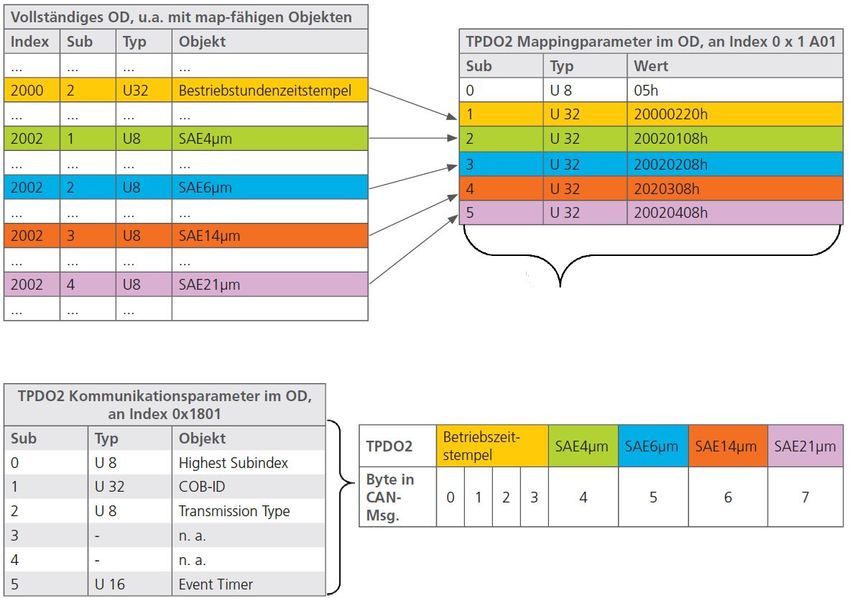
Bühler Technologies GmbH, Harkortstr. 29, D-40880 Ratingen
Tel. +49 (0) 21 02 / 49 89-0, Fax: +49 (0) 21 02 / 49 89-20
Internet: www.buehler-technologies.com
E-Mail: fluidcontrol@buehler-technologies.com

Read this instruction carefully prior to installation and/or use. Pay at-
tention particularly to all advises and safety instructions to prevent in-
juries. Bühler Technologies can not be held responsible for misusing
the product or unreliable function due to unauthorised modifications.

All rights reserved. Bühler Technologies GmbH 2021

Document information
Document No........................................................... BE150102
Version......................................................................... 03/2021

BPM

Contents
1   Introduction..................................................................................................................................................................................................................... 3
    1.1   Intended Use......................................................................................................................................................................................................... 3
          1.1.1  Improper Use ......................................................................................................................................................................................... 3
    1.2 Glossary .................................................................................................................................................................................................................. 3
    1.3 Functionality......................................................................................................................................................................................................... 4
    1.4 Component list..................................................................................................................................................................................................... 4
    1.5 Model key............................................................................................................................................................................................................... 5
    1.6 Scope of Delivery.................................................................................................................................................................................................. 5
2   Safety instructions......................................................................................................................................................................................................... 6
    2.1 Important advice ................................................................................................................................................................................................. 6
    2.2 General hazard warnings ................................................................................................................................................................................. 6
    2.3 Notices on the product ...................................................................................................................................................................................... 8
3   Transport and storage .................................................................................................................................................................................................. 9
4   Installation and connection ...................................................................................................................................................................................... 10
    4.1 Installation site requirements....................................................................................................................................................................... 10
    4.2 Hydraulic Connection ...................................................................................................................................................................................... 10
    4.3 Mount .................................................................................................................................................................................................................... 11
    4.4 Mechanical Load ................................................................................................................................................................................................. 11
    4.5 Electrical Connections...................................................................................................................................................................................... 12
          4.5.1   Pin Assignment (Top View).............................................................................................................................................................. 12
          4.5.2 Analog Current Output (4..20 mA) ................................................................................................................................................ 13
          4.5.3   Switching Inputs And Outputs....................................................................................................................................................... 15
          4.5.4 Calibration............................................................................................................................................................................................ 16
5   Operation and Control................................................................................................................................................................................................. 17
    5.1 Before Initial Use ................................................................................................................................................................................................ 17
    5.2 Start Screen .......................................................................................................................................................................................................... 17
         5.2.1   Status Indication................................................................................................................................................................................. 17
         5.2.2   Time ........................................................................................................................................................................................................ 17
         5.2.3   Displayed Standard............................................................................................................................................................................ 17
         5.2.4 Ordinal Numbers ................................................................................................................................................................................ 18
    5.3 Menu And Operation ....................................................................................................................................................................................... 18
         5.3.1   Menu Structure................................................................................................................................................................................... 19
         5.3.2   Operating Modes............................................................................................................................................................................... 20
         5.3.3   Alarm Configuration ......................................................................................................................................................................... 21
         5.3.4   Analog Configuration........................................................................................................................................................................ 23
         5.3.5   Standard................................................................................................................................................................................................ 23
         5.3.6 Flow Configuration ............................................................................................................................................................................ 23
         5.3.7   Communication .................................................................................................................................................................................. 23
         5.3.8   CAN Baudrate ..................................................................................................................................................................................... 24
         5.3.9 Display Configuration....................................................................................................................................................................... 25
         5.3.10 Sensor Parameters ............................................................................................................................................................................. 25
         5.3.11 Language............................................................................................................................................................................................... 27
    5.4 RS232 Communication..................................................................................................................................................................................... 27
         5.4.1   Interface Parameters......................................................................................................................................................................... 27
         5.4.2 Read Commands................................................................................................................................................................................ 28
         5.4.3   Configuration Commands.............................................................................................................................................................. 30
         5.4.4 Checksum Calculation (CRC) ........................................................................................................................................................... 33
    5.5 CAN Communication........................................................................................................................................................................................ 34
         5.5.1   CANOpen.............................................................................................................................................................................................. 34
    5.6 Classification Systems..................................................................................................................................................................................... 44
         5.6.1   Particle Size Definition..................................................................................................................................................................... 44
6   Cleaning And Maintenance....................................................................................................................................................................................... 48
7   Service and repair......................................................................................................................................................................................................... 49
    7.1 Removal information ...................................................................................................................................................................................... 49
    7.2 Troubleshooting ................................................................................................................................................................................................ 50

BE150102 ◦ 03/2021                                                                                                                                                                 Bühler Technologies GmbH                          i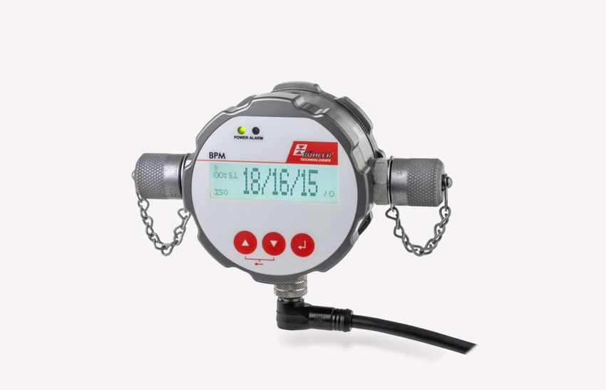
BPM

      7.3       Accessories............................................................................................................................................................................................................ 51
8     Disposal ........................................................................................................................................................................................................................... 52
9     Appendices..................................................................................................................................................................................................................... 53
      9.1 Technical Data.................................................................................................................................................................................................... 53
      9.2 Standard pin assignment ............................................................................................................................................................................... 54
      9.3 Cable Lengths ..................................................................................................................................................................................................... 54
      9.4 Particle Contamination ................................................................................................................................................................................... 55
10 Attached documents ................................................................................................................................................................................................... 56

ii     Bühler Technologies GmbH                                                                                                                                                                              BE150102 ◦ 03/2021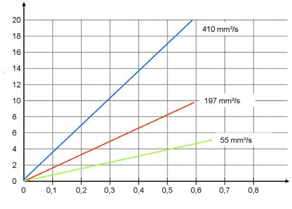
BPM

1 Introduction

1.1 Intended Use
This product is a hydraulic component.
This device is an optical particle monitor used to monitor the cleanliness of fluids. It uses the principle of light extinction (atten-
uation of radiation) and measures particles in the fluid.
The measured values were converted into standardised cleanliness classes and output on the display. Various ports can be used
to read and transmit the measurement data.
It connects to the system with the fluid via two Minimess© M16x2 ports.
The product may be used as follows:
– Monitoring the cleanliness of a fluid,
– Contamination level trend analysis.
The product is only intended for professional use, not for private use.
The intended use also includes reading and understanding this documentation, particularly chapter Safety instructions [>
page 6] in full.

1.1.1 Improper Use
Any use not specified under intended use is considered improper use, thus prohibited.
Installing or using unsuitable products in safety-related applications can cause intended operating states in the application res-
ulting in personal injury and/or property damage. Therefore only use a product for safety-related applications if this use is ex-
pressly specified and permitted in the product documentation. For example, in Ex protection areas or in safety-related parts of a
control unit (functional safety).
Conveying media other than those listed in chapter Technical Data [> page 53] is prohibited.
Bühler Technologies GmbH assumes no liability for damages due to improper use. The user is solely responsible for the risks as-
sociated with improper use.

1.2 Glossary
Abbreviation/designation          Meaning
ON                                Ordinal number
APC                               Automatic particle counter
MTD                               Medium test dust
mm                                Two-digit minute indication
ss                                Two-digit second indication
µm(c)                             Particle size information when using ISO-MTD

BE150102 ◦ 03/2021                                                                                       Bühler Technologies GmbH         3
BPM

1.3 Functionality
The BPM is an optical particle monitor which uses the principle of light extinction.

Fig. 1: Layout and measuring principle of a particle monitor

It consists of a perfused measuring cell (A), a laser (B) and a photodiode (C).
The laser penetrates the measuring cell and hits the photodiode. If a particle passes through the laser beam, the intensity detec-
ted by the photodiode is reduced. The larger the particle, the lower the intensity.
The BPM particle monitor will monitor both the contamination level and the cleanliness trend of fluids. The absolute accuracy
may be different from particle monitors calibrated according to ISO 11171:99. However, the deviation is less than an ordinal num-
ber. Changes are displayed very accurately.
With continuous cleanliness monitoring, changes in the machine can be detected very early.
The quick warning allows taking measures without further heavy contamination, thus possible damage to the entire system.

1.4 Component list

Fig. 2: Component list

        1 Hydraulic fluid connection                                2        Device front panel
       3 "Power" indicator light                                    4        "Alarm" indicator light
       5 Display                                                    6        Hydraulic fluid connection
       7 Select key                                                 8        DOWN key
       9 Sensor cable connection M12x1                              10       UP key

4   Bühler Technologies GmbH                                                                                     BE150102 ◦ 03/2021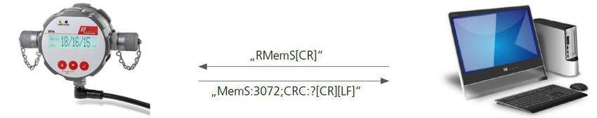
BPM

1 + 6 Hydraulic fluid connection
The device is equipped with two M16x2 Minimess© connections. These are typically used to connect two Minimess© hoses to
connect the particle monitor to the system carrying the fluid. The direction of flow is not important for measurement.
2 + 5 device front panel and display
By default, the display shows the last cleanliness classes detected and the time remaining to the next measurement, or the re-
maining measurement time.
3 "Power" indicator light
This lights up green when connected to the operating voltage.
4 "Alarm" indicator light
This lights up red when there is an internal alarm. Various alarms can be configured for the device. Please observe the explana-
tions throughout these operating instructions.

7 Select key [       ]
The select key is used to jump to the next menu level; when configuring values, the select key is used to jump to the next num-
ber.
8 DOWN key [         ]
10 UP key [      ]
These keys are used to navigate the menu and scroll through the entries.
9 Sensor cable connection M12x1
The device is equipped with an 8-pin M12x1 connection for connecting a sensor cable.
The assignments of the sensor cable and its connection are explained in further descriptions in these operating instructions.
Other key functions:
– Back
simultaneously press UP key [      ] DOWN key [   ].
– Change values:
Use the UP key [ ] or the DOWN key [ ] to select a parameter from the menu. Press the select key to select the parameter. Then
change the value with the UP [ ] or DOWN [ ] key. Press the select key after the last available digit to apply the changes. When
jumping to the next level up before pressing the select key at the end, the changes will not be saved.

1.5 Model key
                                            BPM - 100 - 000 - 1DC2S1A
    Type designation
    BPM Bühler Particle Monitor                                            Outputs
                                                                           1DC2S1A     1x RS232/CAN
    Version                                                                            2x Switching signal input output
    100     Standard compact unit                                                      1x analog signal 4...20 mA

Item no.                 Model
1530001000               BPM-100-000-1DC2S1A

1.6 Scope of Delivery
– Bühler Particle Monitor BPM
– Product Documentation
– 2x Minimess coupler (preinstalled)
– Factory calibration certificate

BE150102 ◦ 03/2021                                                                                   Bühler Technologies GmbH      5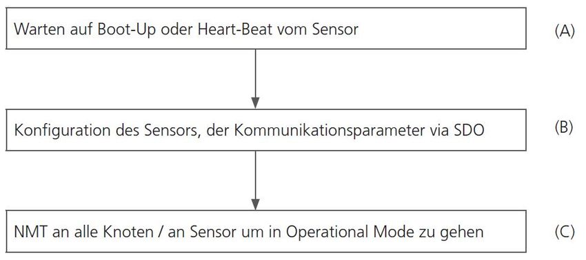
BPM

2 Safety instructions

2.1 Important advice
This device may only be used if:
– The product is being used under the conditions described in the operating- and system instructions, used according to the
  nameplate and for applications for which it is intended. Any unauthorized modifications to the device will void the warranty
  provided by Bühler Technologies GmbH,
– the specifications and markings in the type plate are observed,
– the limits in the data sheet and the instructions must be observed,
– monitoring equipment / protection devices must be connected correctly,
– the device is protected from mechanical damage and vibration,
– service and repairs not described in these instructions is performed by Bühler Technologies GmbH,
– using genuine replacement parts.
These operating instructions are a part of the equipment. The manufacturer reserves the right to change performance-, specific-
ation- or technical data without prior notice. Please keep these instructions for future reference.

Signal words for warnings
                    Signal word for an imminent danger with high risk, resulting in severe injuries or death if not avoided.
    DANGER

                    Signal word for a hazardous situation with medium risk, possibly resulting in severe injuries or death if not
    WARNING
                    avoided.

                    Signal word for a hazardous situation with low risk, resulting in damaged to the device or the property or
    CAUTION
                    minor or medium injuries if not avoided.

                    Signal word for important information to the product.
     NOTICE

Warning signs
These instructions use the following warning signs:

          General warning                                                General information

          Laser warning

2.2 General hazard warnings
The equipment must be installed by a professional familiar with the safety requirements and risks.
Be sure to observe the safety regulations and generally applicable rules of technology relevant for the installation site. Prevent
malfunctions and avoid personal injuries and property damage.

The operator of the system must ensure:
– Safety notices and operating instructions are available and observed,
– The respective national accident prevention regulations are observed,
– The permissible data and operational conditions are maintained,
– Safety guards are used and mandatory maintenance is performed,
– Legal regulations are observed during disposal,
– compliance with national installation regulations.

6   Bühler Technologies GmbH                                                                                       BE150102 ◦ 03/2021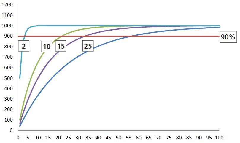
BPM

Maintenance, Repair
Please note during maintenance and repairs:
– Repairs to the unit must be performed by Bühler authorised personnel.
– Only perform conversion-, maintenance or installation work described in these operating and installation instructions.
– Always use genuine spare parts.
– Do not install damaged or defective spare part. If necessary, visually inspect prior to installation to determine any obvious
  damage to the spare parts.
Always observe the applicable safety and operating regulations in the respective country of use when performing any type of
maintenance.

      CAUTION        Laser
                     The particle monitor contains a laser which, when used properly, is classified as a Class 1
                     laser according to DIN EN 60825-1:2001-11. The accessible laser beam is safe under reas-
                     onably foreseeable conditions.
                     In Class 1 laser equipment, e.g. blinding, impairment of colour vision and nuisance can-
                     not be ruled out in the upper performance range.

      CAUTION        Danger due to improper use
                     Property damage
                     The particle monitor may only be used as specified in chapter "Intended Use".
                     Hydraulic oil leaks or spills
                     Environmental pollution and contamination of the groundwater.
                     Use oil binder to soak up leaked hydraulic oil.
                     Contamination due to liquids and foreign objects
                     Premature wear - malfunctions - risk of damage - property damage.
                     Ensure cleanliness during installation to prevent foreign objects, e.g. welding beads or
                     metal shavings from entering the hydraulic lines and causing wear and malfunctions in
                     the product.
                     Ensure the connections, hydraulic lines and add-on parts (e.g. gauges) are clean and free
                     from shavings.
                     Before initial use, verify all hydraulic and mechanical connections are connected and
                     tight and that all seals and fasteners on plug connections are properly installed and un-
                     damaged.
                     Use residue-free industrial wipes to remove lubricants and other contamination.
                     Ensure the connections, hydraulic lines and add-on parts are clean.
                     Ensure contaminants cannot enter when closing the connections.
                     Ensure cleaners do not enter the hydraulic system.
                     Do not use polishing wool or cleaning cloths giving up fluff.
                     Do not seal with hemp.

BE150102 ◦ 03/2021                                                                                    Bühler Technologies GmbH    7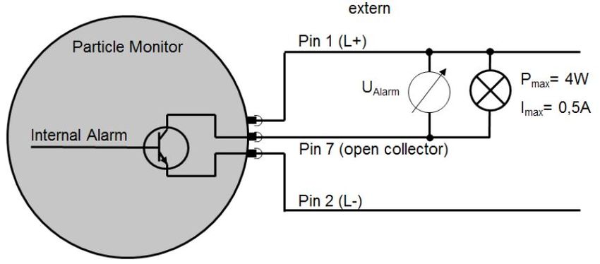
BPM

2.3 Notices on the product
At the back of the device you will also find the notice specifying the laser class as per DIN EN 60825-1 next to the type plate.

Fig. 3: Laser class notice

       NOTICE           Functional limit
                        Damage to the pressure equalisation membranes. Impairment of protection class IP67.
                        At the back of the device is a pressure equalisation membrane which must never be
                        damaged. Take the appropriate care when working on the back of the device.
                        At the back of the device is a decal indicating the laser beam between a Minimess con-
                        nector and the connection for the sensor cable.

At the back of the device is a decal indicating the laser beam between a Minimess connector and the connection for the sensor
cable.

Fig. 4: Laser beam notice

8   Bühler Technologies GmbH                                                                                         BE150102 ◦ 03/2021
BPM 3 Transport and storage Only transport the product inside the original packaging or a suitable alternative. The equipment must be protected from moisture and heat when not in use. It must be stored in a covered, dry, dust-free room at room temperature. BE150102 ◦ 03/2021 Bühler Technologies GmbH 9
BPM

4 Installation and connection

4.1 Installation site requirements
Please observe this information when determining the installation site:
– Connect the particle monitor in the bypass to a pressure line.
– Any direction of flow is permitted.
– The pressures should as constant as possible.
– The pressure may vary, however pressure peaks or strong fluctuations are not permitted.
– The volume flow must be constant, between 50 ... 400 ml/min.
– The flow control or pressure reduction must always be installed downstream from the particle monitor in the return, as
  these can produce turbulences or air bubbles which can result in faulty measurements.
– If a pump is required to generate the necessary flow rate, it should be low pulsation and installed upstream from the particle
  monitor.
– Otherwise bubbles may occur when installed on the suction side, which will cause faulty measurements.
– If air bubbles in the system are suspected, a settling section in form of an approx. 2 m hose will be required in front of the
  device.

4.2 Hydraulic Connection
The sensor has two 1/4" screw connections and comes with factory installed Minimess connectors. The system pressure gener-
ates the necessary flow rate and may need to be throttled downstream from the device.
Any direction of flow is permitted.
The device should be installed in an accessible location to be able to read the display and operate the console. The risk of larger
particles settling increases with the length of the line. Furthermore, particularly when using higher viscosities and Minimess
lines the pressure should be sufficiently high to set the volume flow between 50 and 400 ml/min.
The Minimess connections can be replaced with any other screw connection. In this case, please note the maximum tightening
torque of 25 Nm.
Dirt, shavings or other contaminants must not enter the device when replacing the couplers.

Fig. 5: Hydraulic connection, avoid blind holes in the supply line

Installation should be in the hydraulic circuit in a location relevant to the measuring task with constant pressure conditions.
The pressure may vary, but must not have peaks or strong fluctuations.

10   Bühler Technologies GmbH                                                                                      BE150102 ◦ 03/2021
BPM

                                                      Volume flow:
 Volume flow:

                        Time                                                        Time
Fig. 6: Volume flow parameters

NOTICE! Based on experience, connecting to the control oil line. This location typically has a moderate pressure and an outflow
of max. 400 ml/min typically does not present a problem for the control circuit.
If there is no control circuit, the filtration/cooling circuit can often be used alternatively.
 ∆p in bar

                           Volume flow in L/min

Fig. 7: Flow curve for various viscosities without Minimess connections

The image below shows the pressure difference arising depending on the volume flow for different viscosities. Along with spe-
cifying the necessary volume flow, this can be used to estimate the necessary pressure level.

4.3 Mount
The device has two mounting options:

Orientation               Mounting method                     Torque                                    Length of engagement
Bottom                    4 x M5                              Max. 4 Nm (strength class 8.8)            Min. 5 +1 mm
Side                      2 x M6                              Max. 8 Nm (strength class 8.8)            Min. 6 +1 mm

4.4 Mechanical Load
The mechanical load of the device must not exceed the information in the following table.

Load                                          Frequency                                        Load
max. vibration in all three axes              5 ...9 Hz                                        Amplitude: +/-15 mm 3 g
                                              9 ...16.5 Hz                                     10 g
                                              16.5 ...200 Hz
Tab. 1: Permissible mechanical loads

BE150102 ◦ 03/2021                                                                                          Bühler Technologies GmbH   11
BPM
Fig. 8: Prohibited mechanical stress
4.5 Electrical Connections
Faulty power supply
WARNING
Danger to life – risk of injury
The device must be installed by an electrician.
Observe national and international regulations on the installation of electrical equip-
ment.
Power supply as per EN50178, SELV, PELV, VDE0100-410/A1.
Switch off the machine for installation and connect the device per the following sections. Use a shielded sensor cable.
4.5.1 Pin Assignment (Top View)
Sensor plug pin assignment
Pin Function
1 Power supply L+
2 Power supply L-
3 TxD, CAN low [OUT]
4 RxD, CAN high [IN]
5 Digital input (Start/Stop)
6 Analog output 4...20mA
7 Switching output (Open Collector/Alarm)
8 Signal earth
Shield -
Tab. 2: Pin assignment
The sensor cable must be shielded. To ensure protective class IP67, only use suitable plugs and cables. The tightening torque for
the plug is 0.1 Nm.
12 Bühler Technologies GmbH BE150102 ◦ 03/2021BPM 4.5.2 Analog Current Output (4..20 mA) 4.5.2.1 Measurement Without Load Resistor The current should be measured with a suitable ammeter. Fig. 9: Current measurement without load resistor The ordinal numbers for the various standards are calculated according to the following tables. 4.5.2.2 Measurement With Load Resistor The voltage should be measured with a suitable voltmeter. Fig. 10: Current measurement with load resistor The ordinal numbers for the various standards are calculated according to the following tables. The load resistance cannot be selected arbitrarily. It must be adjusted to the supply voltage. The maximum load resistance can be determined using the following formula: Or alternatively use the following table: Rmax/Ω Supply voltage/V 250 9 400 12 1000 24 Tab. 3: Maximum load resistance 4.5.2.3 Configuration Which ordinal number and standard will be output via the analog current output can be selected in the device menu under "CONFIG. ANALOG". BE150102 ◦ 03/2021 Bühler Technologies GmbH 13
BPM

4.5.2.4 Converting Analog Current Output To Ordinal Number
The analog current output supplies a signal of 4 to 20 mA. The following explains conversions into the respective ordinal num-
bers.

l/mA           ISO 4406:99                 SAE AS 4059E
4              0                           000
12             13                          5
20             26                          12
Tab. 4: Comparison chart current output to ordinal number ISO and SAE

l/mA           NAS 1638                    GOST 17216
4              00                          00
12             7                           15
13             8                           17
14             9                           -
15             10                          -
16             11                          -
17             12                          -
20             -                           -
Tab. 5: Comparison chart current output to ordinal number NAS and GOST

Standard            Ordinal number formula
ISO 4406:99         1.625 ∙I / mA - 6.5
SAE AS 4059 E       0.875 ∙ I / mA - 5.5
NAS 1638            I / mA - 5
GOST 17216          2 ∙ I / mA - 9
Tab. 6: Converting ordinal numbers

4.5.2.5 Sequential Data Output For ISO 4406:99 And SAE AS 4059E
The analog sequential data output function can be used for standards ISO 4406:99 and SAE AS 4059E. In this case, the four or-
dinal numbers are sequentially output via the analog interface (4..20mA) using a set time pattern.
Each sequence starts with a 20 mA signal for 4 seconds. The following shoes a complete output sequence with starting signal.
Sequential output is not available for NAS and GOST.

                      Start                                              Start
     Current

                                                 Time / s
Fig. 11: Sequential data output

14   Bühler Technologies GmbH                                                                                  BE150102 ◦ 03/2021
BPM
4.5.3 Switching Inputs And Outputs
4.5.3.1 Digital Input
The digital input is required for measuring mode: Digital I/O. Pin 5 must be connected to either L- or L+ to start and stop a meas-
urement.
Additional information see chapter Digital I/O [> page 20].
4.5.3.2 Switching Output
When an alarm occurs, in addition to the red LED and the warning triangle in the display, this can also be identified via the
alarm output on pin 7. See chapter Alarm Configuration [> page 21].
There are two options.
NOTICE! Pin 7 is not a switch in the sense of an NO contact. Depending on the alarm status, pin 7 is connected to earth (L-) or not
connected (floating).
4.5.3.2.1 Option 1
Fig. 12: Wiring diagram switching output option 1
Alarm Explanation With voltage measurement When consumer
connected
True Internal transistor connects pin 7 to pin 2. The resistance R now pre- UAlarm = L- = 0 V
vents a direct short-circuit between pin 1 (L+) and pin 2 (L-). R = 1…10 KΩ
R ≥ 100 Ω
False Pin 7 is not connected internally (floating). UAlarm = L+
R = 1...10 KΩ
R ≥ 100 Ω
Tab. 7: Switching behaviour switching output option 1
4.5.3.2.2 Option 2
Fig. 13: Wiring diagram switching output option 2
BE150102 ◦ 03/2021 Bühler Technologies GmbH 15BPM
Alarm Explanation With voltage measurement When consumer
connected
True Internal transistor connects pin 7 with pin 2. The voltage is measured UAlarm = L+
against L-.
Pmax = 4 W
Imax = 0.5 A
False Pin 7 is not connected internally (floating). UAlarm = L- = 0 V
Pmax = 4 W
Imax = 0.5 A
Tab. 8: Switching behaviour switching output option 2
4.5.4 Calibration
The measuring instrument is calibrated based on ISO 11943.
The equipment required for calibration is primary calibrated according to ISO 11171, thus cannot be traceable to NIST SRM 2806A.
NOTICE! The sign µm (c) indicates particle size calibration using ISO-MTD test dust.
The calibration certificate of the device is valid for 18 months from initial calibration. Subsequent certificates are valid for 12
months.
4.5.4.1 Calibration Note
NOTICE! The function is disabled at the factory.
A message will be displayed when the device needs to be recalibrated. See image below. The device is still fully operational and
supplies measurement results. Hold the enter key [ ] for 2 seconds to clear the message.
The message will then appear again after 500/800 and 900 hours. The device is still fully operational and supplies measure-
ment results. Hold the enter key [ ] for 2 seconds to clear the message.
After 1000 hours the message will flash every 2 seconds. The device is still fully operational and supplies measurement results. It
cannot be cleared.
CALIBRATION
REQUIRED
Fig. 14: Calibration warning display message
NOTICE! The calibration warning in the display can only be cleared by Bühler Technologies GmbH Service.
The hours remaining before the first message appears can be viewed in the device menu under “SENSOR PARAM > OPERATING
HRS" ("HOURSCAL").
16 Bühler Technologies GmbH BE150102 ◦ 03/2021BPM
5 Operation and Control
NOTICE
The device must not be operated beyond its specifications.
5.1 Before Initial Use
Always read and understand the operating instructions before starting the equipment.
– Always observe the information related to intended use, operating conditions and technical data.
– Mount the particle monitor as per chapter Installation and connection [> page 10].
– Cables and hoses must be outside the area in which operating personnel moves around (tripping hazard).
5.2 Start Screen
The start screen shows the system status.
Status indication Status indication no time
Time in hh:mm:ss
Displayed standard Ordinal numbers for 4/6/14/21 μm
Fig. 15: Start screen, running and paused measurement, no time
5.2.1 Status Indication
– Measurement running
– Laser adjusts (flashing) at the start of each measurement for approx. 2 to 3 seconds.
– Device paused II
5.2.2 Time
– Measurement running:
Specifies the elapsed or remaining time for the current measurement depending on the operating mode. Specified in
[minutes:seconds]
– Pause mode:
Indicates the time until the next measurement. Specified in [minutes:seconds]
– When changing the pause time in pause mode and it is less than the elapsed time, the display will read "- - : - -". The informa-
tion will display until the original time remaining has expired.
After that, a new pause time is active.
5.2.3 Displayed Standard
Information about the current standard displayed, ISO, SAE, NAS or GOST. This is selected from the menu.
BE150102 ◦ 03/2021 Bühler Technologies GmbH 17BPM 5.2.4 Ordinal Numbers Display of the ordinal numbers for the last measurement. The number of ordinal numbers can vary depending on the selected standard. Standards GOST and NAS only show one ordinal number. NOTICE! Ordinal numbers according to ISO 4406 between 1 and 6 are always displayed as ≤ 6. According to ISO 4406, the or- dinal number for the 21 µm measuring channel is not analysed. The measured value, however, is displayed as additional in- formation and indicated as a reduced size. 5.3 Menu And Operation The [ ] or [ ] key is used to navigate the menu and entries. Press the select key [ ] to jump to the next level. To go back, simultaneously press the [ ] and [ ] key. To change values, press the [ ] key to jump to the next place. The number to change will be marked, then use the arrow keys [ ] and [ ] to change. Press [ ] after the last place to con- firm and apply the changes. Jumping to the higher level before the last confirmation, the changes will be discarded. 18 Bühler Technologies GmbH BE150102 ◦ 03/2021
BPM

5.3.1 Menu Structure

  OPERATING MODE               TIMING              LATENCY                 Set time

                             DIGITAL I/O     MEASUREMENT TIME              Set time

                                 KEY             STD. ALARM             Set cleanliness

                             AUTOMATIC          FILTER MODE             Set cleanliness

   CONFIG. ALARM            ALARM TYPE         TEMPERATURE                Select limit

                           ALARM MEMORY          AUTOM. OFF

                                                  CONFIRM
                           LOW-PASS FILTER

                                              Select filter system
  CONFIG. ANALOGUE          Select output

     STANDARD              Select standard

   CONFIG. FLOW                 AUTO

                                FIXED             Select flow

   COMMUNICATION                TYPE             Select type

                           CAN BAUDRATE         Set baudrate +
                                                  resistance

                            NOTE -ID CAN        Select node ID

                          BAUDRATE RS232       Select baudrate

                            AUTOM. SEND.       Select send data

   CONFIG. DISPLAY            LIGHTING        Select lighting type

                             CONTRAST           Adjust Contrast

                           MEASUREMENT          Display current      Display measurement
   SENSOR PARAM.
                             RESULTS            measurement                 history

                            ELECTRONICS         Display electr.-
                                                  parameter

                          OPERATING HOURS      Display operating
                                                     hours

                                             Display errors with
                            ERROR INFO
                                                   history

                             SET FLOW         Display flow as bar

      LANGUAGE             Select language

Fig. 16: Menu Structure

BE150102 ◦ 03/2021                                                                         Bühler Technologies GmbH   19
BPM 5.3.2 Operating Modes There are four operating modes which can be configured in the menu. When a measurement starts, the internal laser automatically adjusts. This process can be identified by the symbol [ ] flashing in the display and typically takes approx. 2 to 3 seconds. After this, the symbol will light up steady and measurement starts. Pause mode can be identified by the [II] symbol. NOTICE! Measurement times must be between 30 and 300 seconds. For cleanliness levels according to ISO 4406:99 of 15 (at 4 µm©) and better, the measurement time should be at least 120 seconds. The default is 60 seconds. 5.3.2.1 Timed Measurement The BPM uses the set measurement time and pauses between measurements. Here, note the following setting options: Setting limit Min. value/seconds Max. value/seconds Measurement time 30 300 Pause time 1 86400 (24 h) Measurement time factory setting 60 Pause time factory setting 10 Tab. 9: Setting limit timed measurement The default setting of 60 seconds measurement time and 10 seconds pause yields a new measurement every 70 seconds. Note on the time data in the start screen: – Measurement running: Time remaining to the end of measurement (countdown) – Pause mode: Time remaining to the next measurement (countdown) 5.3.2.2 Digital I/O A measurement is running [ ] as long as pin 5 of the M12 plug is connected to the supply voltage (L+) or is not connected. When connecting pin 5 to earth (L-, Pin 2), pause mode [II] is active. The maximum input current on pin 5 is 10 mA. Note on the time data in the start screen: – Measurement running: Elapsed time (incremental) – Pause mode: Measurement time display for the last measurement (static display) Assignment pin 5 Function Supply voltage (L+) Measurement running [ ] Not connected Measurement running [ ] Earth (L-, Pin 2) Pause mode [II] Tab. 10: Assignment pin 5 for measuring mode I/O 5.3.2.3 Key There are two options for starting and ending a measurement. – Manually pressing the [ ] key. – Using a "Start" and "Stop" command via the communication line. This can be done using RS232, CANopen or CAN J1939. After completing a measurement, the measurement result will appear in the start screen. The recommended minimum and maximum measurement time must be observed. Note on the time data in the start screen: – Measurement running: Elapsed time (incremental) – Pause mode: Measurement time display for the last measurement (static display) 20 Bühler Technologies GmbH BE150102 ◦ 03/2021
BPM

5.3.2.4 Automatic
In automatic mode, the measurement time is determined dynamically depending on the flow rate and the particle concentra-
tion.

A measurement runs until the following conditions are met:
– A defined number of particles was detected AND
– the measurement time is at least 45 seconds OR
– the measurement time is greater than 300 seconds
Once the conditions are met, the result in determined and displayed. The number of necessary particle can be changed via the
serial port with the command "WAutoParts". However, this should only be changed by an experienced user. The factory setting is
200.

Note on the time data in the start screen:
– Measurement running: Elapsed time (incremental).
– Pause mode: Not used, a new measurement is automatically started.

5.3.3 Alarm Configuration

5.3.3.1 Alarm Type
There are three different alarm modes which can be configured in the menu.
All three alarms are linked. If one of the three alarms is active, this is indicated by:
– Indicator light "Alarm" lights up red,
– Flashing warning triangle with exclamation point in the display,
– Alarm output pin 7 active,
– Specific bits set in the error codes (ERC).
NOTICE! Measurement results of 0 (ZERO) are considered implausible. In this case, alarm handling is ignored. This does not ap-
ply to the temperature alarm.

5.3.3.1.1 Standard Alarm
A separate limit can be set for each ordinal number (ON) measured. To ignore a size range, set the smallest value. The alarm is
activated once a measured cleanliness class reaches or exceed the set limit.

Standard          Setting range            Value for deactivation            Alarm condition
ISO 4406:99       0, 1, 2 ... 28           0                                 ON 4 µm ≥ limit OR
SAE AS 4059E      000, 00, 0, 1, 2...12    000                               ON 6 µm ≥ limit OR
                                                                             ON 14 µm ≥ limit OR
                                                                             ON 21 µm ≥ limit
NAS 1638          00, 0, 1, 2 ...12        00                                ON ≥ limit
GOST 17216        00, 0, 1, 2 ...17        00
Tab. 11: Alarm configuration standard alarm

5.3.3.1.2 Filter Mode
A separate limit can be set for each ordinal number (ON) measured. To ignore a size range, set the smallest value. The alarm is
activated once a measured cleanliness class reaches or falls below the set limit.

Standard          Setting range            Value for deactivation            Alarm condition
ISO 4406:99       0, 1, 2 ... 28           0                                 ON 4 µm ≥ limit OR
SAE AS 4059E      000, 00, 0, 1, 2...12    000                               ON 6 µm ≥ limit OR
                                                                             ON 14 µm ≥ limit OR
                                                                             ON 21 µm ≥ limit
NAS 1638          00, 0, 1, 2 ...12        00                                ON ≥ limit
GOST 17216        00, 0, 1, 2 ...17        00
Tab. 12: Alarm configuration filter mode

BE150102 ◦ 03/2021                                                                                   Bühler Technologies GmbH     21
BPM
5.3.3.1.3 Temperature Alarm
Here you can set a temperature limit. The temperature alarm is active when the limit is reached or exceeded. To disable, set the
limit to "00".
The measured temperature does not directly correspond to the measured oil temperature. Setting range: 00…85 (00 = disabled).
5.3.3.2 Alarm Memory
There are two options to remove an indicated alarm. The setting can be found in the menu.
1. Auto off
If the conditions for an alarm are no longer met, the alarm is automatically removed.
2. Confirm
The alarm will continue to be indicated, even if the conditions for an alarm are no longer met. It will be displayed until it is
manually cleared.
It can be manually cleared by simultaneously pressing the UP [ ] and DOWN [ ] key.
5.3.3.3 Low-Pass Filter
Brief rises in the concentration (peaks) can occur in a hydraulic system which are not representative of the entire system, by us-
ing a hand valve. The BPM detects this change and indicates it accurately.
The low-pass filter ensures that if an alarm limit has been set, an alarm will not be triggered with every peak. The particle con-
centrations relevant for the alarm are smoothed internally and only output if a sustained measurement change triggers an
alarm. The measurement output and display are not affected by the filtration.
– At a volume flow of 0 ml/min or an ISO class of 0 at 4 µm the filter function is automatically disabled.
– Setting range: 1…255 (1 = disabled)
– Factory setting: 2
– Recommended value: ≤ 10
The following chart shows a step response for various low-pass filter values. The table specifies how many measurements must
be completed for the internal concentration to reach an alarm evaluation of 90 % of the actual concentration measured.
Concentration / p/ml
Measurement no.
Fig. 17: Step response for low-pass filter values 2, 10, 15 and 25
Low-pass filter value 2 5 10 15 25 50 100
Number of measurements before 90% 3 10 21 33 56 113 229
Tab. 13: Low-pass filter values to reach the 90 % threshold
22 Bühler Technologies GmbH BE150102 ◦ 03/2021BPM
5.3.4 Analog Configuration
The measurement results can be output via the analog current output (4..20 mA). The following table shows a list of settings.
For measuring the current and conversions see Analog Current Output (4..20 mA) [> page 13].
Menu selection Analog current output
4 µm Status output of the ordinal number for 4 µm regardless of the configured standard ISO or SAE
6 µm Status output of the ordinal number for 6 µm depending on the configured standard ISO or SAE
14 µm Static output of the ordinal number for 14 µm depending on the configured standard ISO or SAE
21 µm Static output of the ordinal number for 21 µm depending on the configured standard ISO or SAE
SEQUENTIAL (default) Sequential output of the ordinal numbers for 4, 6, 14 and 21 µm depending on the configured stand-
ard ISO or SAE
NAS 1638 Output regardless of configured standard. So the LCD can show ISO, SAE or GOST, however the analog
current output delivers the NAS.
GOST 17216 Output regardless of configured standard. So the LCD can display ISO, SAE or NAS, however the analog
current output delivers GOST.
Tab. 14: Configuration analog current output
5.3.5 Standard
The cleanliness ouptut can be selected based on one of the following standards:
– ISO 4406:99
– SAE AS 4059E
– NAS 1638
– GOST 17216
Please remember, SAE AS 4059E will not analyse sizes 38 and 70 µm in separate channels.
The setting only applies to the display in the start screen. The internal memory and output via the digital interface (CAN or
RS232) show all standards.
Which standard is selected can be seen at the bottom left of the start screen.
5.3.6 Flow Configuration
5.3.6.1 Automatic
In addition to the particle size and count, the BPM also calculates a volume flow index to calculate the particle concentration.
The calculated volume flow index is not an exact measurement of the volume flow. This is an internal calculation value which
can be used as an indicator when installing and setting up the device. The device should not be considered or used as a flow
meter.
5.3.6.2 Fixed
The particle concentration is then calculated based on the fixed volume flow. Enter the value in ml/min.
Please note, the actual and fixed volume flow must not be significantly different. Otherwise the particle concentration calcu-
lated from it will not be correct.
5.3.7 Communication
There are various settings which can be configured in the menu.
BE150102 ◦ 03/2021 Bühler Technologies GmbH 23BPM 5.3.7.1 Type Here you can select how the digital interface is configured. Only one type can be selected. The physical connection is always the same. The types are: – RS 232 – CANOpen – CAN J1939 – AUTO CANOPEN (factory setting) – AUTO J1939 The setting is activated after restarting the device. When selecting "AUTO", the type is determined by the physical voltage level at the digital interface. The type (RS232 or CAN) is automatically detected once when switching on the device. CANopen and CAN J1939 are operated at the same physical voltage levels. If type "CAN" is detected, the CANopen protocol is used (factory setting). To use J1939, "AUTO J1939" must be activated accordingly. For more information see chapter Configuration Commands [> page 30]. 5.3.8 CAN Baudrate The baudrate refers to the transfer rate of the CANopen and CAN J1939 protocol. The baudrate uses the physical unit kilobits per second. The available settings are: – 125 BAUD – 250K BAUD – 500K BAUD – 1000K BAUD – TERM. CAN When activating "TERM. CAN", the transmission line in the device is terminated at a load resistance of 120 Ohm. 5.3.8.1 CAN Node ID The node ID is the address used to address the device via the CAN Bus. The node ID is required for the CANopen and CAN J1939 protocol. Setting range: 1 … 127 (decimal) Factory setting: 10 (decimal) 5.3.8.2 RS232 Baudrate The baudrate refers to the transfer rate for the RS232 protocol. The baudrate uses the physical unit byte per second. The available settings are: – 9600 BAUD – 19200 BAUD – 57600 BAUD (transfer rate for firmware updates) – 115200 BAUD When connecting the device via the RS232 port, the superior instance must always run at the same baudrate. 24 Bühler Technologies GmbH BE150102 ◦ 03/2021
BPM

5.3.8.3 Auto Send
When activating auto send, the measurement result is automatically output via the RS232 port immediately after the measure-
ment. The data string sent corresponds to the response to the command "RVal".
For additional information see chapter Read Commands [> page 28].
Data string examples:
$Time:78.8916[h];ISO4um:0[-];ISO6um:0[-];ISO14um:0[-];ISO21um:0[-];SAE4um:000[-];
SAE6um:000[-];SAE14um:000[-];SAE21um:000[-];NAS:00[-];GOST:00[-];Conc4um:0.00[p/ml];
Conc6um:0.00[p/ml];Conc14um:0.00[p/ml];Conc21um:0.00[p/ml]; FIndex:50000[-];MTime:60[s];
ERC1:0x0000;ERC2:0x0000;ERC3:0x0000;ERC4:0x0800;CRC:Ä

5.3.9 Display Configuration
There are various display settings.
– Illumination:
  Choose whether the backlight is always on or automatically switches off after 10 seconds.
– Contrast:
  Adjust the contrast along a bar display.
  UP key [ ] = increase contrast

   DOWN key [        ] = reduce contrast Confirm with the enter key [    ]

5.3.10 Sensor Parameters

5.3.10.1 Measurement Results
Shows the results of the last valid measurements. Use the UP [       ] and DOWN [   ] key to show all results for a measurement. Use

the enter key [      ] to jump to the previous measurement result.
Selecting the standard changes the appearance of the ordinal numbers.

         MEASUREMENT RESULTS                       MEASUREMENT RESULTS

        OPERATING HOURS                            OPERATING HOURS

         MEASUREMENT RESULTS                       MEASUREMENT RESULTS

         FLOW INDEX                                FLOW INDEX

         MEASUREMENT RESULTS                      MEASUREMENT RESULTS

Fig. 18: Measurement result and history

BE150102 ◦ 03/2021                                                                                     Bühler Technologies GmbH   25
BPM
5.3.10.2 Electronics
Shows internal sensor parameters. This cannot be changed by the user.
– Laser current:
Current used to operate the internal laser. The value should be between 1 and 2.8 mA. If the value is outside this range, there
is a risk of malfunction. See chapter Troubleshooting [> page 50].
– PD voltage:
Voltage of the internal detector. The value should be between 3.7 and 4.3 V. If the value is outside this range, there is a risk of
malfunction. See chapter Troubleshooting [> page 50].
– Temperature:
Temperature of internal electronics. The value shown does not directly correspond to the oil temperature.
– Amplification:
Adjusted amount for the internal detector.
5.3.10.3 Operating Hours
– Sensor:
Operating hours counter for the device. The counter is active as soon as the device is powered.
– Laser:
Operating hours counter for the laser. The counter is only active during a measurement procedure.
– Hourscal:
Shows the hours until the next device calibration. If the value is 0 (ZERO), the time has either expired or the function is dis-
abled. If the time is expired, a message will appear in the start screen.
5.3.10.4 Error Information
The BPM collects a variety of errors, information and operating statuses and combines these in four 16 bit values, the ERC (error
code). These are always displayed in hexadecimal format.
The ERC’s are generated and saved after every measurement. The display shows the last 256 ERC’s. You can browse through
these with the UP [ ] and DOWN [ ] key.
To ensure the ERC’s can be allocated to the individual measurements, the respective operating hour is displayed at the top right.
– 1/256 = ERC for the last valid measurement
– 256/256 = ERC for the oldest valid measurement
ERROR INFO ERROR INFO
Fig. 19: Error information (ERC) display
26 Bühler Technologies GmbH BE150102 ◦ 03/2021BPM
5.3.10.5 Flow Settings
If the flow is auto detected, it can be displayed as a bar graph. The bar is scaled from 50 to 400 ml/min. The display is used to
check the correct flow during initialization.
The display is refreshed every 10 seconds.
The flashing letters L (Low) and H (High) indicate the value is above or below the limit, which must be avoided.
If the flow is configured as a fixed static value, this will also be indicated. However, in this case the bar will not change.
SET FLOW
SET FLOW
SET FLOW
Fig. 20: Bar diagram of the flow
5.3.11 Language
The menu can be displayed in different languages. The available languages are:
– English – Czech – Polish
– German – Spanish – Turkish
– French – Italian
– Dutch – Portuguese
5.4 RS232 Communication
The BPM has a serial port for readout and configuration.
This requires a PC and a suitable terminal program or readout software. The sensor must be connected to a free COM port on a
computer. A suitable communication cable for the serial connection between the sensor and computer/control unit is available
on request. If the computer does not have a serial COM port, a USB to serial adapter can be used.
5.4.1 Interface Parameters
– Baudrate: 9600 (default)/19200/57600/115200 – Stop bits: 1
– Data bits: 8 – Flow control: None
– Parity None
BE150102 ◦ 03/2021 Bühler Technologies GmbH 27You can also read