Glassfront Bev-Max 2 Vender - Model DN5800 prior to 0001-8511AE
←
→
Page content transcription
If your browser does not render page correctly, please read the page content below
Glassfront Bev-Max 2 Vender
       Model DN5800
       prior to 0001-8511AE

                                            Operation
                                            Service
                                            Parts
                                            Troubleshooting
                                            Manual

                               Dixie-Narco, Inc.
                               P.O. Drawer 719
Manufactured by                Williston, SC 29853-0719
                               803-266-5001
                               fax: 803-266-5049
                               Visit us on the web: www.dixienarco.com

                                                               803,904,110.11

                                                                           1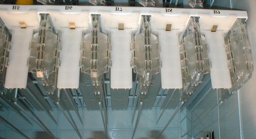
Table of Contents
GENERAL INFORMATION ............................................................................................ 4
Vender Safety Precautions .......................................................................................... 4
Product Identification .................................................................................................. 4
Physical Characteristics .............................................................................................. 4
INSTALLATION & SETUP........................................................................................4 - 9
Receiving Inspection ................................................................................................... 4
Unpacking The Vender........................................................................................... 4 - 5
Electrical Requirements .............................................................................................. 5
Ground The Vender .................................................................................................... 5
Installation & Setup Instructions .............................................................................. 5 - 6
Placing the Vender On Location.............................................................................. 6 - 7
Leveling the Vender.................................................................................................... 7
Spacing the Vender .................................................................................................... 7
Installing Labels & Product ID Cards ............................................................................ 7
Coin Changers And Other Accessories ........................................................................ 7
Set Temperature Control ............................................................................................. 8
Loading the Vender..................................................................................................... 8
Loading the Coin Changer........................................................................................... 8
Power AC Distribution Box .......................................................................................... 8
Vending Machine Controller (VMC).............................................................................. 8
Keypad ...................................................................................................................... 8
Digital Display ............................................................................................................ 8
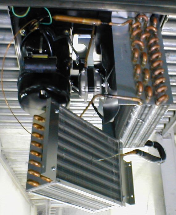
Refrigeration System ............................................................................................. 8 - 9
Shelf Assembly........................................................................................................... 9
Double Gate Assembly................................................................................................ 9
Slide / Pusher Assembly ............................................................................................. 9
Motor Picker Assembly................................................................................................ 9
PROGRAMMING ................................................................................................... 10 - 23
General .................................................................................................................... 10
External Display Items .............................................................................................. 10
Normal Operation Messages ..................................................................................... 10
Initial Programming............................................................................................ 10 - 11
Quick Reference Menu Items .................................................................................... 12
Service Mode ....................................................................................................13 – 15
Test Mode .........................................................................................................15 – 18
Setup Mode.......................................................................................................18 – 22
Setup Mode 2.................................................................................................... 22 - 23
GENERAL MAINTENANCE ........................................................................................24
Power ...................................................................................................................... 24
Cleaning .................................................................................................................. 24
MAJOR COMPONENT DESCRIPTION.....................................................................25
AC Distribution Box ................................................................................................... 25
CONTROL BOARD ......................................................................................................26
Controller Connections .............................................................................................. 26
TROUBLESHOOTING......................................................................................... 27 – 42
XY Issues .......................................................................................................... 27 - 29
XY Not Working Flow Chart ....................................................................................... 30
Plunger Home Flow Chart ......................................................................................... 31
X Axis Home Flow Chart ........................................................................................... 32
Y Axis Home Flow Chart ........................................................................................... 33
XY Slams to Top/Right or Left Flow Chart .................................................................. 34
Picker Cup Not Working Flow Chart ........................................................................... 35
Picker Cup at Wrong Location Y Axis Flow Chart ........................................................ 36
Picker Cup at Wrong Location X Axis Flow Chart ........................................................ 37
Delivery Port Door Flow Chart ................................................................................... 38
Coin Acceptance ...................................................................................................... 39
2
Bill Acceptors ........................................................................................................... 39
        Control Board ........................................................................................................... 39
        All Coins Rejected Flow Chart ................................................................................... 40
        All Bills Rejected Flow Chart ...................................................................................... 41
        Incorrect Change Dispensed Flow Chart .................................................................... 42
        Selection Will Not Vend Flow Chart ............................................................................ 43
        Ice / Frost on Evaporator Flow Chart .......................................................................... 44
        Condensate on Outside of Product Door Flow Chart ................................................... 44
        Compressor Will Not Stop Flow Chart ........................................................................ 44
        Compressor Will Not Start Flow Chart ........................................................................ 45
        Machine Not Cooling Flow Chart ................................................................................ 46
ELECTRICAL DIAGRAMS & SCHEMATICS.................................................. 47 – 55
        Block Diagram Domestic ........................................................................................... 47
        Block Diagram Export ............................................................................................... 48
        Vender Wiring Diagram Cabinet (Domestic & Export)........................................... 49 - 50
        Vender Wiring Diagram Door (Domestic & Export)...................................................... 51
        Vender Wiring Diagram Power & Lighting (Domestic only)........................................... 52
        Vender Wiring Diagram Power & Lighting (Export only)............................................... 53
        Compressor Parts Diagram ....................................................................................... 54
        AC Distribution Box J2 Port Test Voltages .................................................................. 55
PARTS LIST AND DIAGRAMS .......................................................................... 56 – 84
        Machine Front View ...........................................................................................57 – 58
        Cabinet Detail Product Area ...............................................................................59 – 60
        Cabinet Detail Service Door Area........................................................................61 – 62
        XY Motor Picker Unit.......................................................................................... 63 - 64
        Service Door Outside .........................................................................................65 – 66
        Service Door Inside............................................................................................67 – 68
        Gate Tray Detail ................................................................................................69 – 70
        AC Distribution Box ............................................................................................ 71 - 72
        Lighting.................................................................................................................... 73
        Refrigeration Unit Fin & Tube Condenser ............................................................74 – 76
        Electronics ............................................................................................................... 77
        Harnesses .........................................................................................................78 – 79
        Labels / Decals / Misc. .............................................................................................. 80
        Screws & Nuts...................................................................................................81 – 82
        Washers, Bolts, & Misc. Hardware ......................................................................83 – 85

                                                                                                                                          3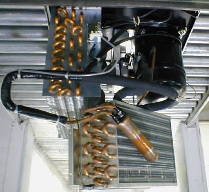
VENDER SAFETY PRECAUTIONS                                  PHYSICAL CHARACTERISTICS
Please read this manual in its entirety. This service
                                                                                              DN5800
information is intended for use by a qualified service
technician who is familiar with proper and safe                           HEIGHT    72” (1828.8 mm)
procedures to be followed when repairing, replacing or
adjusting any Dixie-Narco vender components. All                           WIDTH    47” (1193.8 mm)
repairs should be performed by a qualified service
technician who is equipped with the proper tools and            DEPTH CABINET       32” (812.8 mm)
replacement components, using genuine Dixie-Narco
factory parts.                                                     DEPTH WITH
                                                                                    33.5” (850.9 mm)
                                                                 SERVICE DOOR
              REPAIRS AND/OR SERVICING                                      BASE 4.5” (114.3 mm)
              ATTEMPTED BY UNQUALIFIED
              PERSONS CAN RESULT IN                          SHIPPING WEIGHT        764 lbs. (346kg)
              HAZARDS DEVELOPING DUE TO
              IMPROPER ASSEMBLY OR                         Glass door is 37.5” (876.3 mm) wide, 67” (1701.8
              ADJUSTMENTS WHILE                            mm) high
              PERFORMING SUCH REPAIRS.
              PERSONS NOT HAVING A PROPER
              BACKGROUND MAY SUBJECT                       RECEIVING INSPECTION
              THEMSELVES TO THE RISK OF
                                                           DO NOT STORE THE VENDER OUTSIDE.
              INJURY OR ELECTRICAL SHOCK
              WHICH CAN BE SERIOUS OR EVEN                 Upon receipt, inspect the vender for any shipping
                                                           damage. If there is any damage, have the delivery
              FATAL.
                                                           driver note the damage on the bill of lading and notify
                                                           Dixie-Narco. Although the terms of sale are FOB
                                                           shipping point, which requires the consignee to
PRODUCT IDENTIFICATION                                     originate shipping damage claims, Dixie-Narco will
First production of Bev Max 2 Venders was March            gladly help if you must file a claim.
2005. The production date of Dixie-Narco products is
determined by the date code incorporated in the serial     UNPACKING THE VENDER
number.
The vender serial number takes the form xxxx-yyyy          Remove the stretch wrap, fiberboard edge protectors
                                                           and corrugated front protector from the outside of
zz. The first 4 digits (xxxx) identify the specific
                                                           vender.
vender. The next 4 digits (yyyy) identify the
manufacturing run that the vender was built in. The                       Do not store the vender with stretch
last two alpha characters (zz) identify the quarter and                   wrap on. Stretch wrap could bond to
the year the vender was built.           The first alpha                  the vender’s surface, which could
character identifies the quarter as follows:                              damage the finish.
             st
        A=   1 Quarter                                     Remove the shipping boards from the bottom of the
              nd
        B=   2 Quarter                                     vender.     The shipping boards are attached by the
              rd
        C=   3 Quarter                                     leveling legs. To avoid unnecessary damage to the
              th
        D=   4 Quarter                                     leveling legs or base, remove the shipping boards by
                                                           using a 1-1/2 inch socket type wrench to unscrew the
The second alpha character identifies the year:            leveling legs. Be sure to replace the legs after
   D = 2005           H = 2009                             removing the shipping boards.
   E = 2006           I = 2010                             Once the vender is unpacked, check the recovery unit
   F = 2007           J = 2011                             for any additional parts, price/ product labels,
   G = 2008                                                service/operation manual or other information
                                                           concerning factory-equipped accessories such as coin
                                                           mech and validator.

                                                                                                                 4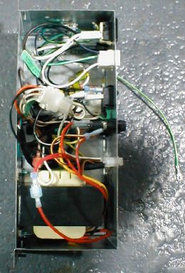
WARNING: TO AVOID THE                       If the outlet will not accept the power cord plug,
             POSSIBILITY OF A FIRE                       contact an electrician to install a proper AC outlet.
             HAZARD, DO NOT STORE                                       FAILURE TO COMPLY WITH
             ANYTHING     OR    ALLOW                                   THESE INSTRUCTIONS MAY
             DEBRIS OF ANY KIND TO                                      SUBJECT THE USER TO THE RISK
             ACCUMULATE      IN   THE                                   OF INJURY OR ELECTRICAL
             BOTTOM OF THE SERVICE                                      SHOCK WHICH CAN BE SERIOUS
                                                                        OR FATAL. PERIODICALLY
             AREA, IN AND AROUND THE                                    INSPECT THE POWER SUPPLY
             REFRIGERATION                                              CORD FOR DAMAGE. IF THE
             COMPARTMENT OF THE                                         CORD BECOMES DAMAGED IT
             CABINET, OR IN FRONT OF                                    MUST BE REPLACED WITH THE
             THE EVAPORATOR AND                                         SAME SIZE AND TYPE CORD.
                                                                        CONTACT DIXIE-NARCO FOR
             CONDENSER COILS.                                           ASSISTANCE.

             WARNING: ENSURE THAT                        INSTALLATION AND SETUP
             POWER IS DISCONNECTED                       INSTRUCTIONS
             FROM THE VENDER BEFORE
             INSPECTING OR REPLACING                     ELECTRONIC LOCK
             THE LAMPS, OTHER                            The electronic lock provided in the vender consists of
             ELECTRICAL COMPONENTS,                      a door mounted, motor driven 2 point latching system,
                                                         cabinet mounted latch and strike system, an infrared
             OR WORKING WITH OR                          controlled CPU, and a remote control key (FOB). The
             ADJUSTING THE VENDING                       design is modular and allows for easy field service.
             MECHANISM. FAILURE TO
             COMPLY WITH THESE                           The electronic remote key (FOB) features a rolling
             INSTRUCTIONS MAY                            code system which cannot be decoded if it is lost or
                                                         stolen. After the vender has been unlocked, a new
             SUBJECT THE USER TO THE                     key can be programmed into it any number of times.
             RISK OF ELECTRICAL                          If a key is lost or stolen, it is recommended you
             SHOCK OR MECHANICAL                         change the lock code in the field as soon as possible.
             INJURY, WHICH CAN BE                        Changing the lock code requires a new key and
             SERIOUS OR FATAL.                           pressing the PROGRAM button on the lock inside the
                                                         vender. The lock does not need to be changed for re-
                                                         keying.
ELECTRICAL POWER NEEDED
Refer to the cabinet serial number plate to determine        Important: For security reasons all Electronic
the correct voltage and frequency for the machine. In                   Door Lock Venders are shipped less
the US and Canada this is 120Vac, 60Hz, 1P. In                          keys. Customers will need to contact
Europe, Australia, and other export countries, this is                  the    Electronic      Door    Lock
220/230/240Vac, 50Hz, 1P depending upon your                            manufacturer to order keys.
country voltage. The serial plate also specifies the
ampere rating of the machine. This machine must be       A power bypass connector, located in the product
plugged into a properly rated receptacle with its own    delivery port, allows auxiliary power to be applied via
circuit protection (fuse or circuit breaker.             a battery pack to the electronic lock in the event that
DO NOT USE AN EXTENSION CORD.                            power is not available or there has been a failure of
                                                         the internal power supply.        In the event of an
                                                         emergency, battery power is applied to the connector
GROUND THE VENDER                                        and the door can be opened and closed using the
The vender is equipped with a three-wire power           FOB.
supply cord and MUST be plugged into a properly
grounded outlet.                                         The electronics uses an infrared transmission system,
               DO NOT REMOVE THE GROUND                  which functions similar to a television remote control.
               PIN OR IN ANY WAY BYPASS,                 The transmission signal is line-of-sight, which requires
               MODIFY, DEFEAT, OR DESTROY                you to aim the remote at a specific place at close
               THE GROUNDING SYSTEM OF                   range to prevent the accidental opening of several
               THE VENDER.                               venders at the same time.
                                                                                                               5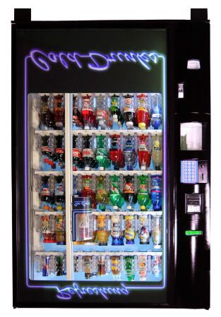
Open the service door and apply power to the AC
TO OPEN THE ELECTRONIC DOOR LOCK:                         distribution Box (if equipped with a bill acceptor, the
                                                          acceptor should cycle twice). The display on the door
    1.   Plug the vender into a properly powered          will briefly show the software version in use as
         outlet.                                          “Software ###.## (ie 080.01) followed by the default
    2.   Hold the key FOB 0 to 3 inches in front of the   idle message “ENJOY A REFRESHING DRINK”, the
         Delivery Port Door and press the button on       fluorescent lamp should be lit and the cooling unit
         the key FOB.                                     should start.      If the display shows “OUT OF
         Note: The wide end of the FOB should face        SERVICE”, or the cooling unit fails to start, refer to the
                 the door.                                TROUBLESHOOTING SECTION beginning on page
    3.   The lock will begin releasing the door. Th e     28.
         display will indicate OPENED. After the motor
         has stopped running, you can pull the door
         open.                                            SERVICE NOTE
                                                          Battery Backup
TO CLOSE THE ELECTRONIC DOOR LOCK:
                                                          The battery backup is used to maintain the date and
                                                          time in case of power interruptions, or any time the
CAUTION: DO NOT SLAM THE DOOR CLOSED.
                                                          main power is off. When the vender is shipped, the
Slamming the door closed can damage the electronic
                                                          battery is connected and memory is being maintained.
locking device.
                                                          If the vender is to be stored for long periods of time,
    1. Push the door to the cabinet until the lock
                                                          disconnecting the battery is recommended.           The
        motor starts.       The display will indicate:
                                                          following steps will guide you through this procedure.
        CLOSED
    2. Continue to push the door for approximately 2
                                                              •   Open the service door, turn the main power
        to 3 seconds after the lock motor starts. The
        lock will pull the door closed tightly.                   switch to the off position or unplug the main
                                                                  power harness located on the front of the
    3. When the lock motor stops the door will be
                                                                  power box.
        locked. Before leaving the vender, ensure
        that the door is locked.                              •   Locate the control board mounted on the rear
                                                                  wall.
The electronic door lock assembly is supplied by Tri          •   Remove the battery from its holder (B 1).
Teq Lock and Security. Dixie-Narco, Inc. does not
carry parts for the Tri Teq Electronic Door Lock.
For parts and assistance, please contact:

         Tri Teq
                                                          PLACING THE VENDER ON
         701 Gullo                                        LOCATION
         Elk Grove Village, IL 60007                                         !! CAUTION !!
         Tel: 847-640-7002
         Fax: 847-640-7008                                                DO NOT TRANSPORT THE
         Email: gary@triteqlock.com                                       VENDER TO OR FROM THE
                                                                          LOCATION LOADED WITH
                                                                          PRODUCT OR DAMAGE TO THE
MANUAL LOCK                                                               VENDER MAY RESULT.
Open the service door on the right side using the key
provided in the coin return cup, or if shipped with a
                                                          The vender is intended for INDOOR USE ONLY. It
locking clip, remove the clip and install the lock.
                                                          should be kept out of direct sunlight and away form
Ensure there is no power to the AC Distribution Box.
                                                          any heat source. This machine is not suitable for
On venders with a main power switch on the AC
                                                          installation in an area where a water jet or hose and
Distribution Box the switch needs to be in the OFF
                                                          nozzle may be used.
position. On venders with a main power quick
disconnect plug on the AC Distribution Box the quick
                                                          The vender must be on a solid, flat and level surface.
disconnect plug needs to be unplugged. Check that
                                                          Ensure the flooring can bear the weight load of a fully
all connectors are firmly seated on the control board
                                                          loaded vender (approximately 1109 lbs. or 413kg).
and at the various components on the service door
                                                          The vender must be positioned close enough to an
(coin mech, keypad, etc.).
                                                          electrical outlet so that an extension cord is not
Retrieve the main power plug from the hole in the rear
                                                          required. If the machine will be subject to user misuse
of the vender and plug the cord in a properly
                                                          or vandalism, it is recommended that the vender be
grounded 120VAC, 15 Amp receptacle (U.S. and
                                                          secured to the floor or wall as described in Dixie-
Canada).
                                                          Narco Technical Bulletin 344. Due to the large size

                                                                                                                  6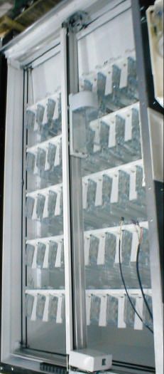
and weight of the Vender, never attempt to move the        INSTALLING PRICE LABELS
Vender with a Hand Truck or Stair Climber. Use a
                                                           Pricing labels included in the literature package kit.
pallet jack or Vender/Cooler Dollies at all times when
                                                           They range in price from .25 to 9.95. Remove the
moving the Vender. The vender should never be slid
                                                           pricing label sheets from the service manual package
or pushed in place. Never side load the leveling legs;
                                                           and gently remove the label corresponding to the
doing so will cause damage to the legs. Do not
                                                           vend price of each selection by tearing at the
transport the vender to or from customer locations
                                                           perforation. The label is installed at the top of the
loaded with product, as damage may result due to
                                                           front knuckle. Once installed, push the label firmly
excessive weight. Call the Dixie-Narco Technical
                                                           against the front of the knuckle. This will insure the
Service      Department    or     your      Dixie-Narco
                                                           label is locked in place.
Representative for assistance.

                                                           INSTALLING PRODUCT ID CARDS
LEVEL THE VENDER
                                                           To assist with consistent loading, product ID cards are
Adjust the front leveling legs, ensuring that an even
                                                           included for the slide assemblies with every vender
gap exists between the glass door and the top
                                                           and should be installed into the product pusher to
security angle and receiver box, and then level the
                                                           designate to the route driver which product the column
cabinet front to rear. A carpenter’s level will help
                                                           is set for. To install the flavor card, simply detach it
verify that the vender is level. Leveling legs are
                                                           from the sheet at the perforation and slide it into the
adjusted using a wrench or socket 1 ½” in size. If the
                                                           slots in the product pusher.
vender is to be used in a bank of equipment, check
the top and sides for proper alignment. If you are
unable to properly level the vender, select an alternate   COIN CHANGERS & OTHER
location. NEVER PLACE OBJECTS UNDER THE                    ACCESSORIES
LEVELING LEGS OF THE VENDER
                                                           The vender can have an MDB coin changer installed
                    DANGER                                 and can have an MDB bill acceptor installed as well.
                THE VENDER MUST BE PROPERLY                Note: Bev Max 2 will work with an MDB bill acceptor
                LOCATED AND LEVELED. IF THE                only. If the MDB coin changer and other MDB
                MACHINE WILL BE SUBJECT TO                 accessories are not factory installed, refer to the
                USER MISUSE OR VANDA LISM IT IS            instructions received form the manufacturer of the
                RECOMMENDED THAT THE                       MDB coin changer and other MDB accessories for
                VENDER BE SECURED TO THE                   proper set-up and installation.
                FLOOR OR WALL AS DESCRIBED
                IN DIXIE-NARCO TECHNICAL                   The vender will support the following Domestic MDB
                BULLETIN 344 TO MINI MIZE THE              coin changers:
                RISK OF INJURY OR DEATH FROM
                TIPPING. CALL THE DIXIE-NARCO                      Coinco 9302GX, USG-701 Quantum
                TECHNICAL SERVICE                                  Mars   TRC-6510, TRC-6512, TRC-4010
                DEPARTMENT OR YOUR DIXIE-                          Conlux CCM-5G 1-2-3-4-5
                NARCO REPRESENTATIVE FOR
                ASSISTANCE.                                The vender will support the following domestic MDB
                                                           Bill validators:
SPACE THE VENDER
                                                           Coinco BA-30 B, BA-50B       Coinco Mag 50
Do not block the rear of the vender. Maintain a
                                                           Mars VN 2512          Conlux NBM-3000 Series
minimum of 4 inches (10 cm) from the wall to ensure
adequate airflow to the condenser and compressor.
                                                           The vender will support MDB card readers.
At the rear of the vender, make sure nothing obstructs
the air exhaust at the bottom of the cabinet.
                    WARNING
                TO AVOID THE POSSIBILITY OF A
                FIRE HAZARD, DO NOT STORE
                ANYTHING OR ALLOW DEBRIS OF
                ANY KIND TO ACCUMULATE IN THE
                BOTTOM OF THE DOOR, IN THE
                BOTTOM OF THE SERVICE AREA,
                IN AND AROUND THE
                REFRIGERATION COMPARTMENT
                OF THE CABINET, OR IN FRONT OF
                THE EVAPORATOR AND
                CONDENSER COILS.

                                                                                                                 7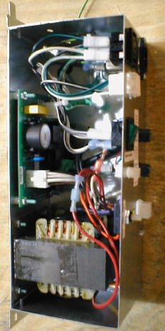
SETTING THE TEMPERATURE                                             page 17 in the programming section for more
                                                                    information)
CONTROL                                                    (For additional information about coin mechanism,
This vender is equipped with an electronic                 refer to the manufacturer’s instructions.)
temperature sensor and a manual defrost thermostat.
This temp sensor is factory pre-set to maintain a          POWER AC DISTRIBUTION BOX
cabinet temperature of 37 degrees Fahrenheit. It is
                                                           The power distribution box is where the 120VAC input
also a good practice to ensure the proper operating
                                                           voltage is broken down to the main operating voltages
temperature prior to installing the vender on location.    of the vender (24 VAC and 12 VAC) by a transformer.
To set the temperature, apply power to the vender
                                                           Those voltages are sent to the controller via the P1 (3
and allow it to run for several hours with the glass
                                                           pin) connector. It also contains 3 fuses that protect
door closed or until the minimum cabinet temperature       the VMC, transformer, and motors.           The power
is achieved. Then, using the method below, verify the
                                                           distribution box also distributes AC power to the lights,
temperature inside the cabinet:
                                                           evaporator fan, and refrigeration system, which are
                                                           always energized when the vender is powered up. It
With an electronic temperature sensor, use the
                                                           is located inside the service area, mounted to the
keypad on the service door to show cabinet
                                                           back wall.
temperature in Fahrenheit by pressing the F key
followed by the asterisk (¯) key or in Centigrade by
pressing the C key followed by the asterisk key. The       VENDING MACHINE CONTROLLER (VMC)
temperature will be shown on the digital display           The vending machine controller is the heart of the
located on the front of the service door.                  Glass Front Vender and is located on the rear wall
                                                           inside the service area. It is flash programmable and
The defrost control is located on the side of the          may or may not include the program chip (EPROM),
refrigeration unit. The defrost control is preset and is   which controls all aspects of the vender. It also
not adjustable.                                            contains the power supply which regulates the
                                                           voltages required to operate the motors as well as the
                                                           coin mechanism, digital display and all logic functions
                                                           in the vender.
LOADING THE VENDER
CAN/BOTTLE DRINK TRAYS
                                                           Keypad
The Bev Max 2 Vender does not require spacers or
shims to vend most packages. Load product in each          The keypad is located on the front of the service door.
column one package at a time insuring that the             It consists of a 6 inch X 3 inch matrix, membrane
package being loaded is in front of the product            switch pad and an overlay. The pad utilizes the letters
pusher. Insure that the package is stable within the       A thru F on the left side and numbers 1 thru 0 along
column (doesn’t move excessively from side to side).       with the ¯ symbol and Clr to the right. The keypad is
After loading the vender, test vend each column to         where the vender programming is accomplished and
insure proper operation. Please contact a Service          where the customers make their selections.
Representative or refer to the proper Technical
Publication for any special settings you may need.         DIGITAL DISPLAY
                                                           The digital display is located directly above the
                                                           keypad on the front of the service door. It is used to
LOADING CHANGE TUBES                                       convey information to the consumer as well as to the
The changer tubes can be loaded using one of the           person programming the vender.
following methods:
     1. Load the coin mechanism with coins to the          REFRIGERATION SYSTEM
         desired level by inserting coins in the loading   The refrigeration system is a single piece unit and is
         slots on the coin tube front.                     hermetically sealed. In the EM2001 model consist of
         Minimum coin tube levels are:                     a ½ horsepower compressor, with a single fin and
         6-8 nickels                                       tube style condensing unit with one fan, the
         7-8 dimes                                         condensation overflow pan and the evaporator. The
         5-6 quarters                                      evaporator is located behind the panel on the back
         Note: A low coin level in the coin tubes will     right side of the cooling compartment directly adjacent
         interfere with operation of the bill validator.   to the bottom shelf. The remainder of the unit is
     2. For exact cash accountability and to insure        located behind the refrigeration unit cover panels,
         maximum dollar bill acceptance, load the          mounted in the bottom of the cabinet. This unit is
         mechanism utilizing the coin insert slot on the   designed for easy removal and replacement from the
         front of the vender while in the coin tube        front of the vender as a complete assembly. An
         fill/dispense mode in the test menu. (see         electronic     thermostat   regulates    the    cabinet
                                                           temperature. The bulb of the thermostat is attached
                                                                                                                  8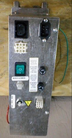
to the evaporator coils and reads the temperature of       MOTOR PICKER ASSEMBLY
air being pulled in to the evaporator coil.
                                                           The motor picker assembly is located on the XY door
                                                           vend mechanism. Its purpose is to pick the product
SHELF ASSEMBLY                                             from the column and deliver the product to the
Typically, there are 5 shelf assemblies in every           delivery port. The motor picker assembly is mounted
vender; however, this can vary depending upon the          on the XY assembly and bolts in position.
configuration specified at the time of ordering. Each
can/bottle shelf consists of 9 columns. Each shelf is      The X axis runs left to right. The X axis assembly is
capable of holding a variety of packages. The shelf        cabinet mounted to prevent any cabinet torque and
assembly consists of the tray, where all of the            has one belt to synchronize the top and bottom when
following parts are mounted: Double Gate assembly,         the X moves left or right.
and the slide/pusher assembly. These items are
discussed in detail below.                                 The Y axis runs up and down and has the Picker Cup
                                                           Assembly attached. A top channel is used to contain
DOUBLE GATE ASSEMBLY (Can/Bottle                           and hide the e chain and wiring.
Trays)
                                                           Both X and Y motors have encoders for positioning.
The double gate assembly is mounted on the front
portion of the tray assembly and contains the vending
mechanism. Incorporated in the gate assembly are
the front and rear knuckle assemblies as well as the
product kicker. In standby operation, the front knuckle
is in the blocking position, which holds the front
displayed product in position to be vended. The rear
knuckle assembly is in a flat position, which allows
product to enter the gate area, and the kicker is flush
to the rear knuckle assembly. A stainless steel pin is
inserted through the rear most portion of the front
knuckle assembly and connects to a gear box below
the tray. When a selection is made, the plunger
pushes the lever toward the back of the tray. At the
same time the front knuckle is opened into a flat
position, the rear knuckle is closed to a blocking
position, holding the remaining product out of the gate
area, and the kicker is extended to firmly push the
front displayed product off of the tray. The plunger is
energized for approximately 1-½ seconds to allow
ample time for the displayed product to be ejected
from the shelf. The plunger is then released and the
front knuckle returns to the blocking position, the rear
knuckle and kicker return to their standby position and
the next product slides into the vend display position.

SLIDE/PUSHER ASSEMBLY (Can/Bottle
Trays)
The slide/pusher is located on the bottom of each
product column. Its purpose is to provide a slick,
friction resistant surface for the product to rest on.
The tall product pusher is mounted on the top of the
slide and incorporates a coil spring in the body that
attaches to the bottom of the slide through a slit. This
spring adds needed tension to insure that all products
in the column remain tight against each other and are
allowed to progress into the gate area. Although
these pushers reduce the effects of dirt and grime,
periodic cleaning and lubrication of the slides is
recommended.        DO NOT USE SOLVENTS OR
ABRASIVE MATERIALS TO CLEAN ANY PORTION
OF THE TRAY.

                                                                                                                9
INITIAL PROGRAMMING
PROGRAMMING
                                                           DATE/TIME
GENERAL INFORMATION                                        To set date/time enter “SETUP MODE 1” by opening
In order to fully utilize the many features of your        the service door and pressing the Service Button
vender it is important that you first understand the       three (3) times.        Press the number “5” and
options available and procedures for programming the       “DATE/TIME” will show on display. Press the “¯ ” key
vending controller unit (control board).                   and display will show the current year, month, date,
All programming, testing, and service functions are        and time setting currently in the system in following
accomplished by using the keypad in an easy to             format: 2005 Apr 28 15:45 with the year highlighted.
follow, display prompted format. There are four modes      Press the numbers to enter the current year and
of operation for servicing, testing, and setting up your   Month will then be highlighted. To change the month
vender. The modes of operation are accessed by,            press the A key to scroll forward through the months
opening the service door, and pressing the service         or the B key to scroll backward through the months.
button on the control board.                               With the correct month showing, press the “¯” key to
The service button will cycle through each of the four     save and Date will then be highlighted. Press the
modes in turn: Service Mode, Test Mode, Set-Up             numbers to enter the current date and then the hour
Mode 1 and Set-Up Mode 2. In each of these modes,          will then be highlighted. Note: Hours are shown in 24
the “A” key is used to scroll through the available        hour format. Press the numbers to enter the current
options/settings within that mode/selection. (Note: In     hour and then the minutes will then be highlighted.
each of the mode selections, pressing the character        Press the numbers to enter the current minutes. The
key next to the listed option will take you directly to    display will then change to show “OK? ¯=Y (Yes)
that feature - see menu items chart on page 12.), the      CLR = N (No)” and the setting you entered. You must
“¯” key is used as an enter key to select the currently    press ¯ Key to save the new date and time entered.
displayed item/feature, and the “CLR” key is used as a     Pressing CLR Key will revert to the date and time
done or exit key. Closing the service door or pushing      setting. Press the “CLR” key to return to “SETUP
the service door switch will exit the function you are     MODE”.
currently in and place the vender back in service.
                                                           SET PRICES
EXTERNAL DISPLAY ITEMS                                     To set the prices enter the “SERVICE MODE” by
                                                           opening the service door and pressing the Service
(HOT KEYS)                                                 Button once.       Allows the setting of regular and
Allows the service technician to view several items via    secondary prices for an individual item, a complete
the display without opening the vender. There are four     tray, or the entire machine. Factory setting is $99.95.
options that can be viewed externally:                     Press the number “7” on the keypad and the display
    1. Display temperature in degrees “C”. To              will show “SET PRICE”. Press the “¯” key and the
         view, press the “C” then press the ¯ key. The     display will show “1 = Regular Pricing, 2 = Secondary
         display will then show the vender’s inside        Pricing”. To set regular prices press number 1 key
         temperature in degrees “C”.                       and display will show “Regular $##.##”. To set price:
    2. Display date/time. To view, press the “D”                1. All selections. Press the keypad numbers of
         key, then press the “¯” key. The display will              the price you wish to use. As numbers are
         then show the current date and time.                       entered the numbers will shift in from the right
    3. Display temperature in degrees “F”. To                       as they are entered. Note: The CLR key will
         view, press the “F” key, then press the “¯ ”               remove the last # of the price. Once the
         key. The display will show the vender’s inside             desired price is showing on the display press
         temperature in degrees “F”.                                the “¯” key and the display will show
    4. Display current software revision. To view,                  “PR$##.## All Set”, press “*” to set more
         press the “B” key, then press the “¯ ” key. The            prices or CLR to return to SET PRICES.
         display will then show the current software                Press CLR Key again to return to SERVICE
         revision in the controller.                                MODE.
                                                                2. One tray. Press the keypad numbers of the
NORMAL OPERATION MESSAGES                                           price you wish to use. As numbers are
                                                                    entered the numbers will shift in from the right
At initial power-up, the program will start and the
                                                                    as they are entered. Note: The CLR key will
display will briefly show the software version in use as
                                                                    remove the last # of the price. Once the
Software ###.## (i.e. 080.01), followed by the default
                                                                    desired price is showing on the display press
idle message, “ENJOY A REFRESHING DRINK”.
                                                                    the tray letter desired for setting price. Press
                                                                    “¯” and display will show “PR $##.## B(tray
                                                                    letter) Row Set”, press “*” to set more prices

                                                                                                                 10
or CLR to return to SET PRICES. Press CLR 4): Press number 1 Key to set Select Block 1 available
Key again to return to SERVICE MODE. settings, Key 2 for Select Block 2, etc… Once you
3. Single selection. Press the keypad numbers select the Select Block # you wish to set the display
of the price you wish to use. As numbers are will show “Start MTWTFSS Stop 1 00:00 NNNNNNN
entered the numbers will shift in from the right 00:00” with the start time hour highlighted. Press the
as they are entered. Note: The CLR key will numbers to enter the hour you wish to start select
remove the last # of the price. Once the block (Note: hour setting is in 24 hour format.) and
desired price is showing on the display press then the minutes will be highlighted. Press the
the selection desired for setting price. Press number keys to enter the minutes and then the first
“¯” and display will show “PR $##.## B1 day of the weeks current setting will be highlighted.
Selection Set”, press “¯” to set more prices or To change the setting to no press key 2, to yes press
CLR to return to SET PRICES. Press CLR key 1. This will change each setting left to right one
Key again to return to SERVICE MODE. day at a time until all are set then Stop time hour will
The last price entered for a selection is the price that be highlighted. Press the numbers to enter the hour
will be used. For example, If one price on the A tray you wish to stop select blocking and the minutes will
was set to $1.50 using option 3 above and you wish to be highlighted. Press the numbers to set the minutes
change the remaining selections on that tray using and the display will show “OK? ¯ = Y CLR = N” press
option 2, the pricing for the entire tray would take the ¯ Key to save these settings or CLR Key not to
precedence. Conversely, if the price was set using save settings and display will change to show which
option 2 first followed by the single selection using selections are assigned to this block. Press ¯ Key
option 3, the pricing for the remainder of the shelf and display will show “Enter Selection”. Press the
would remain and the new price for the single Keys of the selections you wish to disable followed by
selection would change to the new value. ¯ and display will show “Disabled Continue? ¯ = Y
Press the “CLR” key to return to “SERVICE MODE”. CLR = N”. Note: If you press a tray letter (ie A)
followed by the ¯ Key that entire tray will be set to be
SET NOT AVAILABLE TIMES disabled. Once you have selected all settings and the
Password protected. Before entering or changing this display shows “Disabled Continue? Or Enabled
setting you must enter the password if one has been Continued? ¯ = Y CLR = N press the CLR to return to
assigned. This mode allows up to 4 different time “SET NOT AVAIL TIME”. Press CLR again to return
periods that use of the machine may be restricted. to “SETUP MODE 1”.
To set Not Available Times enter the “SETUP MODE
1” by opening the service door and pressing the
Service Button 3 times. Press the number 3 key; the
display will show “SET NOT AVAIL TIME”. Press the
“¯” key and the display will show “S elect Block (1 –
11BEV-MAX 2 SERVICE MODE MENU ITEMS
(080.21 Menu shown)
SERVICE MODE SETUP MODE 1
A Next Item A Next Item
B Cash Box B Enter Message
C Sales C Clear Message
D Display Temperature D Enable/Disable $
E Set Refrig Temp E Set Happy Hour Time
F Clear Totals F Master Reset
1 Number Sold 1 Machine Number
2 Disable Item 2 Set Happy Hour
3 Sales by Column 3 Set Not Avail. Time
4 Escrow 4 Consumer Overpay
5 Force Vend 5 Date/Time
6 Set Temperature (F or C) 6 Total Sales
7 Set Prices (Regular & Secondary) 7 Health Control
8 Set Shelf Location (G, M1, M2, D, E1, E2) 8 Update Software
9 Relay Toggle 9 Set Lights Off Time
0 Clear Errors 0 Enter New Password
TEST MODE SETUP MODE 2
A Next Item A Next Item
B List Errors B STS Enable
*C Not Used C Custom STS
*D Not Used D Default STS
E Keypad Test E Display STS
F Factory Diagnostics F Set No Vend Limit
1 Tube Fill/Dispense *1 Multivend
2 Daylight Savings Time *2 Not Used
3 Not Available Mode 3 Sold Out Enable
4 Credit Timer Mode 4 Price Display
5 Door Open 5 Storage Temp Enable
6 Power Out 6 Interval Clearing (On/Off)
7 Test Health Guard 7 Set Lights Off
8 Display Health Guard 8 Set Refrigeration Temp
9 Test Vend 9 Set Storage Time
0 Show Checksums 0 Set Storage Temp
*Note: All menu items with the font in red are not available in the current Bev Max 2 Vender programming.
Note: all items in Italics under SETUP MODES require password entry for access if one has been assigned.
FACTORY DEFAULT REQUIRES NO PASSWORD UNTIL NEW PASSWORD OTHER THAN 0000 IS
ENTERED.
Menu items shown above reflect software revision 804,924,08x.x1 and higher
Service Mode Pages 13 through 15
Test Mode Pages 15 through 18
Setup Mode 1 Pages 18 through 22
Setup Mode 2 Pages 22 through 23
12and reload recovery. Press the letter “E” on the
SERVICE MODE MENU ITEMS keypad and display will show “SET REFRIG TEMP”.
Press the “¯ ” key on the keypad and the display will
Note: Menu items in red are not currently read “tt.tx” where x is Fahrenheit or Celsius and tt.t
available. is the degrees. To change the set point press the
key numbers you wish the set point to be
SERVICE MODE (temperature set must be between 32 and 75
Enter SERVICE MODE by opening the service door degrees F). Press the “¯” key to save the new set
and pressing the Service button once. The display point temperature and return to “SET REFRIG
will read “SERVICE MODE”. The following choices TEMP”. Press the “CLR” key to return to “SERVICE
are now available: MODE” or press the “A” key to advance to the next
menu item below.
NEXT ITEM - Press key “A”
CASH BOX - Press key “B” CLEAR TOTALS - Press key “F”
Allows the service technician to clear totals in CASH
Shows the amount of change diverted to the cash
BOX, SALES, NUMBER SOLD, DOOR OPENINGS,
box from the coin mechanism since the last CLEAR
POWER OUTAGES, SALES BY COLUMN, and all
TOTALS or MASTER RESET. To view the cash box
other interval data. Press the letter “F” on the
totals, press the letter “B” on the keypad and the
keypad and the display will show “CLEAR TOTALS”.
display will show “CASH BOX”, then press the “¯”
Press the “¯” key, the display will read Clear Interval
key and the display will show Cash Box $#.##.
Data? ¯ = Y CLR = N. Press the “CLR” key to return
Press the “CLR” key to return to “CASH BOX”.
to “Clear Totals” with out resetting the totals. Press
Press the “CLR” key to return to “SERVICE MODE”
the selection you wish to use and display will return
or press the “A” key to advance to the next menu
to “Clear Totals”. Press the “CLR” key to return to
item below.
“SERVICE MODE” or press the “A” key to advance
to the next menu item below.
SALES - Press key “C”
Shows total sales since last CLEAR TOTALS or NUMBER SOLD - Press key “1”
MASTER RESET. This total includes change not
Shows the total number of items sold since the last
diverted to the cash box and still being held in coin
CLEAR TOTALS OR MASTER RESET. Press the
mechanism escrow tubes To view the total sales
number “1” on the keypad and the display will show
press the letter “C” on the keypad and the display
“NUMBER SOLD”. Press the “¯” key and the
will show “SALES”, then press the “¯ ” key and the
display will show “Number Sold #”. Press the “CLR”
display will show Sales #.##. Press the “CLR” key to
key to return to “Number Sold”. Press the “CLR” key
return to “SALES”. Press the “CLR” key to return to
to return to “SERVICE MODE” or press the “A” key
“SERVICE MODE” or press the “A” key to advance
to advance to the next menu item below.
to the next menu item below.
DISPLAY TEMPERATURE - Press key “D” ENABLE ITEM - Press key “2”
Allows an individual selection, a complete tray, or
Shows the cabinet temperature in degrees Celsius
the entire machine to be enabled or disabled. This is
or degrees Fahrenheit. Press the letter “D” on the
most commonly used when a selection is out of
keypad. The display will show ”Display
order and you are awaiting parts and do not want
Temperature”. Press the “¯” key and the display
the customer to utilize that selection. Press the
will show “Display: ON (or OFF) Press “*” – turn OFF
number “2” on the keypad and the display will show
(or ON)”. Press the ¯ Key to toggle on/off or press
“ENABLE ITEM”. Press the “¯” key and the display
the CLR Key to not change settings. If “on” is
will read “Enter Selection”. There are now three
selected the Display will change to “Set
choices:
Temperature Unit Degrees F (or C) showing the
1. Pressing the “¯” key will toggle between
current setting temperature will be displayed. Press
enabled and disabled for the entire machine,
F for Fahrenheit or C for Celsius. Press the ¯ Key
the display will show the new state i.e.
to save and return to “Display Temperature.” Press
enabled or disabled and display will show
the “CLR” key to return to “SERVICE MODE” or
“Blocked (Unblocked) Continue? ¯ = Y CLR
press the “A” key to advance to the next menu item
= N.
below.
2. Pressing a tray selection followed by “¯ ” will
show the new state of that tray. (For
SET REFRIG TEMP - Key “E” example, pressing “A*” will show the new
Allows the service technician to set the average state for the A tray, the display will show the
product temperature (set point) for initial pull down new state i.e. enabled or disabled and
13display will show “A Blocked (Unblocked) current state. Pressing the “¯ ” key will toggle the
Continue? ¯ = Y CLR = N. state. Press the “CLR” key to return to “Force Vend”.
3. Pressing an item selection will show the new Press the “CLR” key to return to “SERVICE MODE”
state of that item; for example, pressing “A1” or press the “A” key to advance to the next menu
will show the new state of that item, the item below.
display will show the new state i.e. enabled
or disabled and display will show “A1 SET TEMPERATURE SCALE- Press key “6”
Blocked (Unblocked) Continue? ¯ = Y CLR
Allows the service technician to change the scale of
= N.
the temperature in the vender to read in Fahrenheit
If a selection has been disabled in this mode and the
or Celsius as needed. Press the number “6” on the
customer tries to purchase from the programmed
keypad and the display will show “Set Temperature”.
selection(s), the vender will display “SELECT
Press the “¯ ” key and the display will show “Set
ANOTHER ITEM”. Press the CLR Key to show all
Temperature Unit Degrees F (or C)”. Press the C to
items that are blocked or the ¯ Key to disable more
display in Celsius or F to display in Fahrenheit.
items. Press the “CLR” key to return to “Enable
Press ¯ to save and display will return to “Set
Item”. Press the “CLR” key to return to “SERVICE
Temperature”. Press the “CLR” key to return to
MODE” or press the “A” key to advance to the next
“SERVICE MODE” or press the “A” key to advance
menu item below.
to the next menu item below.
SALES BY COLUMN - Press key “3” SET PRICES - Press key “7”
Shows the total number sold from each selection
To set the prices enter the “SERVICE MODE” by
since the last CLEAR TOTALS or MASTER RESET.
opening the service door and pressing the Service
Press the number “3” on the keypad and the display
Button once. Allows the setting of regular and
will show “SALES BY COLUMN”. Press the “¯” key
secondary prices for an individual item, a complete
and the display will read “Select Column”. Select the
tray, or the entire machine. Factory setting is
column to be checked (the total number sold from
$99.95. Press the number “7” on the keypad and
that selection will be on the right side of the display
the display will show “SET PRICE”. Press the “¯”
and the item number will be on the left side of the
key and the display will show “1 = Regular Pricing, 2
display). Press the “CLR” key to return to “Sales by
= Secondary Pricing”. To set regular prices press
Column”. Press the “CLR” key to return to
number 1 key and display will show “Regular
“SERVICE MODE” or press the “A” key to advance
$##.##”. To set price:
to the next menu item below.
1. All selections. Press the keypad numbers
of the price you wish to use. As numbers
ESCROW - Press key “4” are entered the numbers will shift in from the
Allows a bill to be returned if the change return lever right as they are entered. Note: The CLR
is pressed before a selection is made. Factory key will remove the last # of the price. Once
setting is ESCROW OFF. Press the number “4” on the desired price is showing on the display
the keypad and the display will read “ESCROW press the “¯ ” key and the display will show
OFF” or “ESCROW ON”, depending on the current “PR$##.## All Set”, press “¯” to enter more
state. Pressing the “¯” key toggle the vender from prices or CLR to exit to SET PRICE.
ESCROW OFF to ESCROW ON. Example: If 2. One tray. Press the keypad numbers of the
“ESCROW OFF” is showing on the display, pressing price you wish to use. As numbers are
the “¯” key will disable the escrow function and the entered the numbers will shift in from the
display will read ESCROW ON. This feature only right as they are entered. Note: The CLR
affects those machines with a bill validator installed. key will remove the last # of the price. Once
Press the “CLR” key to return to “Escrow”. Press the the desired price is showing on the display
“CLR” key to return to “SERVICE MODE” or press press the tray letter desired for setting price.
the “A” key to advance to the next menu item below. Press “¯” and display will show “PR $##.##
B(tray letter) Row Set”, press “*” to set more
FORCE VEND - Press key “5” (NOT prices or CLR to exit to SET PRICE.
AVIALABLE) 3. Single selection. Press the keypad
numbers of the price you wish to use. As
Forces the customer to make a vend by inhibiting
numbers are entered the numbers will shift
the coin return lever once the minimum vend price
in from the right as they are entered. Note:
line has been met or exceeded The coin return lever
The CLR key will remove the last # of the
will not be inhibited if there is not enough credit to
price. Once the desired price is showing on
vend the lowest priced item or if a vend failure has
the display press the selection desired for
occurred. Factory setting is “FORCE OFF”. Press
setting price. Press “¯” and display will
the number “5” on the keypad the display will read
show “PR $##.## B1 Selection Set”, press
“FORCE OFF” or “FORCE ON”, depending on the
14“¯” to set more prices or CLR to exit to SET Key and the display will show “CLEAR ERRORS”,
PRICE. then press ¯ Key and the display will show “Clear
The last price entered for a selection is the one that All Errors? ¯ = Y CLR = N”. Press the “CLR” key to
is used. For example, If one price on the A tray was return to “Clear Errors”. Press ¯ Key to clear all
set to $1.50 using option 3 above and you wish to errors or press the “CLR” key to return to “SERVICE
change the remaining selections on that tray using MODE”.
option 2, the pricing for the entire tray would take
precedence. Conversely, if the price was set using
option 2 first followed by the single selection using
option 3, the pricing for the remainder of the shelf
would remain and the new price for the single TEST MODE
selection would change to the new value. Press the Enter TEST MODE by opening the service door and
“CLR” key to return to “Set Prices”. Press the “CLR” pressing the blue Service button twice. The display
key to return to “SERVICE MODE” or press the “A” will read” TEST MODE”.
key to advance to the next menu item below.
NEXT ITEM - Press key “A”
SET SHELF LOCATION - Key “8”
Allows the service technician to program the
electronics to match the six different settings
available for the shelves. These settings are LIST ERRORS - Press key “B”
available to vend different package heights. The Allows the service technician to view a list of all
factory default setting is Shelf Setting G. Press the recorded errors. Press the letter “B” on the keypad
number “8” on the keypad and display will show “Set and the display will show “LIST ERRORS”, then
Shelf Location”. Press the “¯” key and display will change to “NONE” if no errors exist or, if errors are
show current setting. To change the setting press present, one of the error prompts below will be
one of the following: A = G setting, B = M1 setting, C displayed. If an error code is displayed, press the
= M2 setting, D = D setting, E = E1 setting, F = E2 “¯” key to view the next error until “END LIST” is
setting. Note G, M1, & M2 settings are used in displayed. With “END LIST” showing on the display,
venders prior to 0001-8487AE and D, E1, & E2 press the “¯” key to clear errors and return to TEST
settings are used in venders 0001-8487AE & higher. MODE. If you wish to exit the list without clearing
Once the desired setting is showing on the display errors, simply push the “CLR” key and the display
press the “¯” key to save the setting. Note: all shelf will return to LIST ERRORS. If the CLR key is
settings have to be physically set to match the pressed prior to reaching the end of the list, the
programmed setting. You can not set the physical display will jump to END LIST. Explanations for the
shelf settings differently. Press the “CLR” key to error codes are listed below. Note: The prompts
return to “Set Shelf Location”. Press the “CLR” key listed will only show on the display if an error has
to return to “SERVICE MODE” or press the “A” key occurred.
to advance to the next menu item below.
NONE No errors have occurred.
RELAY TOGGLE - Press key “9” VEND MECH ERROR
HORIZ – Horizontal Drive System problem.
Allows the service technician to test the Light Relay,
VERT – Vertical Drive System problem.
Fan Relay, and Compressor Relay. Press the
PICKI – Picker not all the way in problem.
number “9” on the keypad and the display will show
PICKO – Picker out switch error problem.
“Relay Toggle”. Press the ¯ Key and display will
PORT – Port Drive System problem.
show “Light A – On or Off”, “Fan B – On or Off”,
VS – Vend Sensor problem.
“Compressor C – On or Off”. Display will show
VMC ERRORS
current status of the relay (not the component the
FRAM – Memory module read/write error.
relay operates). To toggle the state of a given relay
RTC – RTC read/write error, clock error.
press the letter key associated with it on the display.
SF – Decimal error.
Caution: Disconnect power to the compressor before
RCRC – software not loaded properly.
testing the compressor relay. Failure to disconnect
LB – Low battery.
power to the compressor before testing the relay
PWR OUT – Power lost.
could result in damaging the compressor. Press the
KEYPAD ERROR
“CLR” key to return to “Relay Toggle”. Press the
KEYPAD – Keypad not installed.
“CLR” key to return to “SERVICE MODE” or press
COIN MECH ERROR
the “A” key to advance to the next menu item below.
CC – Coin Mech disconnected.
TS – Tube Sensor defective.
CLEAR ERRORS - Press key “0” IC – No coin accepted for 96 hours (4 days).
Allows the service technician to clear errors TJXX – Tube jam.
recorded in the venders data. Press the number “0” CRCH – Check sum.
15You can also read