Investigative Research of an IP Peering Service for NetherLight
←
→
Page content transcription
If your browser does not render page correctly, please read the page content below
Project report

Investigative Research of an IP Peering Service
                for NetherLight
                             August 21, 2020
                                                                      Assessor:
                                                     Prof. dr. ir. Cees de Laat
                                                                  delaat@uva.nl
                                                     University of Amsterdam
                                                                   Supervisors:
                                                        Gerben van Malenstein
                                                                      SURFnet
   ing. Arnold Buntsma
                                               gerben.vanmalenstein@surfnet.nl
   arnold.buntsma@os3.nl
   UvA ID: 12818674                                               Migiel de Vos
                                                                      SURFnet
   ing. Mar Badidas Simó                               migiel.devos@surfnet.nl
   mar.badidassimo@os3.nl                                          Max Mudde
   UvA ID: 12838268                                                   SURFnet
                                                        max.mudde@surfnet.nl
                                                                  Marijke Kaat
                                                                      SURFnet
                                                        marijke.kaat@surfnet.nl
                                                                      Course:
                                                            Research Project 2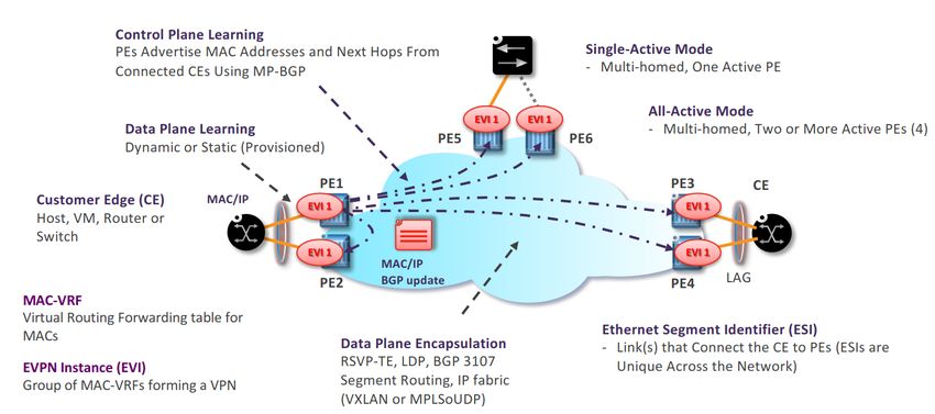
Investigative Research of an IP Peering Service for NetherLight
                                                                                                             Project report

                                                           Abstract
      In this project, we investigate how NetherLight, an exchange that facilitates high bandwidth point-to-point and
      multipoint connections for its clients, can set up a peering service where all its clients can connect. We define its
      requirements, study the best practices and gather common problems that need to be considered when building such
      service. We describe how route servers can be used, which IP address space is most suitable and what security
      measures should be taken. Then, we explored two different solutions, one using EVPN protocol and the other using
      OpenFlow with the Faucet controller. For both options, we described how they can be managed, monitored and
      how scalable they are. Finally, we compare both options and conclude that EVPN requires less effort to implement
      given current NetherLight infrastructure, but OpenFlow is a more advanced solution that offers a more fined-control
      of the traffic, less management effort and vendor independency.
Keywords— Peering service, EVPN, OpenFlow, Software Defined Network (SDN), Internet eXchange Point (IXP)

ing. Arnold Buntsma, ing. Mar Badidas Simó                                                                        page 2 of 28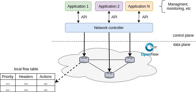
Investigative Research of an IP Peering Service for NetherLight
                                                                                                                                       Project report

Contents
1 Introduction                                                                                                                                                                                                                        4

2 Methodology                                                                                                                                                                                                                         5

3 Background                                                                                                                                                                                                                          5
  3.1 NetherLight . . . . . . . . . . . . . . . . . . . . . . . . . . . . . . . . . . . . . . . . . . . . . . . . . . . . . . . . .                                                                                                   5
  3.2 Best practices on peering services . . . . . . . . . . . . . . . . . . . . . . . . . . . . . . . . . . . . . . . . . . . . .                                                                                                    6

4 Requirements                                                                                                                                                                                                                        8

5 Generic Components                                                                                                                  8
  5.1 Route servers . . . . . . . . . . . . . . . . . . . . . . . . . . . . . . . . . . . . . . . . . . . . . . . . . . . . . . . . 8
  5.2 IP space . . . . . . . . . . . . . . . . . . . . . . . . . . . . . . . . . . . . . . . . . . . . . . . . . . . . . . . . . . . 9
  5.3 Security . . . . . . . . . . . . . . . . . . . . . . . . . . . . . . . . . . . . . . . . . . . . . . . . . . . . . . . . . . . 10

6 Solutions                                                                                                                        10
  6.1 EVPN . . . . . . . . . . . . . . . . . . . . . . . . . . . . . . . . . . . . . . . . . . . . . . . . . . . . . . . . . . . . 10
  6.2 SDN/OpenFlow . . . . . . . . . . . . . . . . . . . . . . . . . . . . . . . . . . . . . . . . . . . . . . . . . . . . . . . 13

7 On- and off-boarding workflow                                                                                                                                                                                                       16

8 Comparison between solutions                                                                                                    18
  8.1 MPLS-EVPN: . . . . . . . . . . . . . . . . . . . . . . . . . . . . . . . . . . . . . . . . . . . . . . . . . . . . . . . . 18
  8.2 VXLAN-EVPN: . . . . . . . . . . . . . . . . . . . . . . . . . . . . . . . . . . . . . . . . . . . . . . . . . . . . . . 19
  8.3 OpenFlow: . . . . . . . . . . . . . . . . . . . . . . . . . . . . . . . . . . . . . . . . . . . . . . . . . . . . . . . . . 19

9 Discussion                                                                                                                                                                                                                          19
  9.1 Generic services . . .    . . . . . .   .   .   .   .   .   .   .   .   .   .   .   .   .   .   .   .   .   .   .   .   .   .   .   .   .   .   .   .   .   .   .   .   .   .   .   .   .   .   .   .   .   .   .   .   .   .   19
  9.2 EVPN . . . . . . . .      . . . . . .   .   .   .   .   .   .   .   .   .   .   .   .   .   .   .   .   .   .   .   .   .   .   .   .   .   .   .   .   .   .   .   .   .   .   .   .   .   .   .   .   .   .   .   .   .   .   20
  9.3 SDN/OpenFlow . . .        . . . . . .   .   .   .   .   .   .   .   .   .   .   .   .   .   .   .   .   .   .   .   .   .   .   .   .   .   .   .   .   .   .   .   .   .   .   .   .   .   .   .   .   .   .   .   .   .   .   20
  9.4 Requirements . . . .      . . . . . .   .   .   .   .   .   .   .   .   .   .   .   .   .   .   .   .   .   .   .   .   .   .   .   .   .   .   .   .   .   .   .   .   .   .   .   .   .   .   .   .   .   .   .   .   .   .   20
  9.5 On- and off-boarding      workflow      .   .   .   .   .   .   .   .   .   .   .   .   .   .   .   .   .   .   .   .   .   .   .   .   .   .   .   .   .   .   .   .   .   .   .   .   .   .   .   .   .   .   .   .   .   .   21
  9.6 Research questions .      . . . . . .   .   .   .   .   .   .   .   .   .   .   .   .   .   .   .   .   .   .   .   .   .   .   .   .   .   .   .   .   .   .   .   .   .   .   .   .   .   .   .   .   .   .   .   .   .   .   21

10 Future Work                                                                                                                                                                                                                        21

11 Conclusion                                                                                                                                                                                                                         22

References                                                                                                                                                                                                                            23

Appendices                                                                                                                                                                                                                            28

Please notice that in this project, the word ”client” will be used with the pronouns he/him/his. However, ”client” does not
represent a single person, male or female, but an entire organisation or institution.

ing. Arnold Buntsma, ing. Mar Badidas Simó                                                                                                                                                                   page 3 of 28
Investigative Research of an IP Peering Service for NetherLight
Project report
1 Introduction
NetherLight is an exchange built and operated by SURFnet and facilitates high bandwidth connections for its clients [1].
SURFnet is the organization that created, operates, and maintains the National Research and Education Network (NREN) of
The Netherlands. Although NetherLight is part of SURFnet, their networks are separated. NetherLight connects research and
education networks with, for example, service providers by facilitating a layer 21 domain. On this layer 2 domain, NetherLight
offers point-to-point and multipoint connections between its clients. The logical overview of NetherLight’s infrastructure can
be seen in figure 1.
Figure 1: Logical Overview of NetherLight’s infrastructure.
NetherLight investigates offering a new service that allows their clients to set up BGP peerings with each other in a fast, man-
ageable, predictable, scalable, and reliable way. Preferably with minimal or no intervention from NetherLight’s management
and operations.
The concept of a peering service is widely used around the world on Internet eXchange Points (IXPs). IXPs offer peering services
where different parties, like ISPs, social media networks, and CDNs, connect and exchange traffic. The clients of NetherLight
are different from clients of an IXP. For NetherLight, the clients are mostly research facilities and exchange research data.
The main goal of this research project is to investigate what options there are to create a layer 2 underlay to facilitate layer 3
peering, as well as investigate how customers can connect to the peering network. Also, to investigate the operational environ-
ment, and give recommendations on which solution is best suited for the use case of NetherLight. The following main research
question was answered:
How can NetherLight facilitate a state-of-the-art peering service for its clients which is flexible, secure, man-
ageable and has a uniform set up?
To answer the main question, the following sub-questions have been defined:
1. What are the requirements for NetherLight (and its customers) for setting up the peering service?
2. What are the options and best practices for setting up a peering service that fulfils the requirements of NetherLight(and
its clients)?
3. How do (used) protocols behave in such environment and which problems can arise?
4. What would the uniform onboarding procedure be for clients who are going to use the peering service?
The requirements are set by NetherLight for the peering service and contain all the technical, functional and non-functional
demands of the solutions.
For answering the second question, we want to make use of the best-suited technologies to build a service that meets NetherLight’s
requirements. Best practices include considering route servers, as well as which IP ranges to use, security and manageability
considerations.
In the third sub-question, we look at how the peering service protocols work. We research if those have problems like an ARP
storm or how ARP spoofing can be prevented. Once known how these protocols will work, NetherLight can predict what will
happen in the network and proactively act on this.
In the last sub-question, we look at how clients can join the peering service in a uniform way that is easy and scalable, without
compromising the security of the service. We investigate how the configuration can be verified before connecting to the actual
peering network. We also look at how this service can be managed with minimum or no involvement of the NetherLight team.
1 Original OSI model: https://standards.iso.org/ittf/PubliclyAvailableStandards/s014258_ISO_IEC_7498-4_1989(E).zip
ing. Arnold Buntsma, ing. Mar Badidas Simó page 4 of 28Investigative Research of an IP Peering Service for NetherLight
Project report
This report is organised in the following sections: In section 2 (Methodology), the methodology is presented. Then, in section 3
(Background ), NetherLight and their current infrastructure is described and some best practices implemented by IXPs. Section
4 (Requirements), answers the sub question regarding the requirements from NetherLight. In section 5 (Generic Components),
there are described the generic components that are needed in all the solutions found. Then, in section 6 (Solutions) the different
researched solutions are described including their options on monitoring and manageability. In section 7 (On- and off-boarding
workflow ), the process to join and leave the peering service is described. Section 8 (Comparison between solutions) provides
a comparison of the researched solutions on the metrics manageability, security, and scalability. In section 9 (Discussion) we
discuss our findings, explain how they comply to the given requirements, motivate the given advice and answer our research
questions. Then after the discussion, in section 10 (future work ) can the future work be found. Finally, closing off with the
conclusion in section 11 (Conclusion).
2 Methodology
For conducting this project, the following approach was used: first step was to define the requirements of NetherLight for the
IP peering service. In appendix D the initial list of requirements can be viewed that the NetherLight team provided. These
requirements where further defined via interviews with the NetherLight team. The requirements have been used to set up the
criteria used to define and evaluate the solutions.
Secondly, a literature study has been performed to research possible solutions for the peering service and to find pitfalls and
their mitigation. We studied the current best practices on IXPs, as well as, the current state-of-the-art approaches for setting
a peering service. This study was done using scientific publications, protocol specifications and documentation. Other sources
of information regarding IXP practices were euro-ix2 , and the database peeringdb 3 .
Likewise, several Internet Exchanges were contacted to determine several solutions for the peering service and gather their best
practices. A list of contacted IXPs can be seen in appendix A and a list of IXPs that replied in the list below. The questions
asked are also in the appendix (see appendix B).
IXPs that answered our questions:
• AAIX - Klagenfurt, Austria. No web page available, information can be found at https://www.peeringdb.com/ix/377
• AMS-IX - Amsterdam, The Netherlands. https://www.ams-ix.net/ams
• CATNIX - Barcelona, Spain. https://www.catnix.net/
• Rheintal IX - Schaan, Liechtenstein. https://www.rheintal-ix.net/
• TouIX - Toulouse, France. http://touix.net/en
• TREX Regional Exchanges - Tampere, Finland. http://www.trex.fi/
We contacted the IXPs by mail or using their web form if no mail was available. Our questions were answered by mail (see
appendix C) except for TouIX, with whom we had two online meetings with their operator, Marc Bruyere.
From these communications, we learned that even though VPLS is used in a lot of IXPs, migrating to EVPN is highly recom-
mended because it was designed to overcome all of VPLS its shortcomings. A better description of VPLS is given in paragraph
6.1. All IXPs use public IP addresses in the peering service. Route servers are not always used, and they are necessary only
after the IXP has over a hundred members, but introducing them at that point is difficult. Also, it is a common practice not
to accept unnecessary protocols (Spanning Tree Protocol variants, routing protocols other than BGP, link local protocols, and
others (DHCP, GARP, GVRP, VTP, ...). All IXPs agree that ARP storms are a severe problem, and they should be avoided, as
they can bring down the entire network. Another common best practice is to allow one MAC address per port to prevent spoofing.
Finally, several solutions for a peering service have been investigated, compared, and proposed. These solutions meet NetherLight’s
requirements and include a detailed description of their advantages and disadvantages, possible shortcomings, and best practices.
3 Background
This section will provide some background information on NetherLight and its topology, and current best practices from IXPs.
3.1 NetherLight
NetherLight’s network is separate from SURFnet’s network. However, both networks are interconnected by multiple 100Gb/s
links. Clients connected to the SURFnet network can use NetherLight’s services using the SURFnet connection because of
their interconnection. Besides SURFnet, other parties connected to NetherLight include, but are not limited to, research and
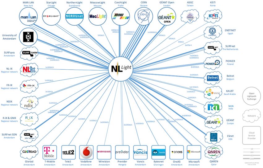
education facilities’ networks, and cloud service providers around the world. An overview of connected parties can be viewed in
2 https://www.euro-ix.net/
3 https://www.peeringdb.com/
ing. Arnold Buntsma, ing. Mar Badidas Simó page 5 of 28Investigative Research of an IP Peering Service for NetherLight
Project report
figure 2. This also shows the type of client they are, for example, an open lightpath exchange or (NREN) network. This figure
is not up-to-date4 , but will give an indication of the clients of NetherLight. NetherLight used to be a member of GLIF (Global
Lambda Integrated Facility) and is now a member of GNA-G 5 .
Figure 2: NetherLight’s connected networks (outdated) [1].
NetherLight currently offers VLANs (IEEE 802.1Q and IEEE 802.1ad) point-to-point and multipoint connections between their
clients. The VLANs are built using Ethernet VPN (EVPN) on top of an MPLS underlay network. A more detailed picture of
NetherLight’s topology and the relation between the network of SURFnet can be seen in figure 3. The dotted lines represent a
layer 2 domain spanning across the networks. A customer can have multiple links to a node or both nodes of NetherLight. The
two nodes are in different locations in Amsterdam.
3.2 Best practices on peering services
It is known that peering services have some pitfalls when building traditionally, as most IXPs have built their peering service
using VPLS. These pitfalls are mostly related to protocols that send broadcast or multicast traffic. In a broadcast domain that
consists of many clients, it is possible that a ’broadcast storms’ can cripple the network [2]. Therefore these storms need to be
taken care of, and will not cause the network to become inoperable.
Because a peering service is a network where many clients are connected, it is of utmost importance that traffic going over the
network is legitimate and not bogus. Therefore, it is wise to limit the type of packets that may enter the network. How and
which protocols must be filtered needs to be investigated in this research. For example, it is not advised to have DHCP, or
OSPF packets going over the network [2]. This is not only a waste of bandwidth but could also be a security risk if clients
receive control packets that are not intended for them but process them.
In a peering service, it is all about peering relations. Therefore, it is essential to keep those secure and no BGP hijacking6 can
take place, or incorrect prefixes are accepted. If this happens, the integrity of the routes will be compromised.
So to summarise, the following pitfalls need to be mitigated when creating a peering network:
4 An up-to-date version was not available
5 https://www.gna-g.net/
6 https://en.wikipedia.org/wiki/BGP_hijacking
ing. Arnold Buntsma, ing. Mar Badidas Simó page 6 of 28Investigative Research of an IP Peering Service for NetherLight
Project report
• Broadcast storms.
• Unwanted packet types.
• BGP hijacking.
There is a global initiative for the security of the peering service, that has set norms for routing security. This is provided by
MANRS, Mutually Agreed Norms for Routing Security 7 . This initiative ”provides crucial fixes to reduce the most common
routing threats” (sic) [3]. There is a special ’MANRS IXP Programme’ were IXPs can join to get the MANRS compliant status.
To achieve this status, an IXP must prove that it does at least three of the actions listed, where the first two are mandatory.
The action set is cited from their website 8 .
1. ”Prevent propagation of incorrect routing information. The IXP implements filtering of route announcements at the route
server based on routing information data (IRR and/or RPKI).”
2. ”Promote MANRS to the IXP membership. The IXP provides encouragement or assistance for members to implement
MANRS actions.” This can be done by one or more of the actions provided on their website 9
3. ”Protect the peering platform. The IXP has a policy of traffic that is not allowed on the peering fabric.”
4. ”Facilitate global operational communication and coordination between network operators. The IXP facilitates commu-
nication among members by providing mailing lists and member directories. The IXP and each of its members has at
least one valid, active email address and one phone number that other members can use in case of abuse, security, and
operational incidents.”
10
5. Provide monitoring and debugging tools to the members. The IXP provides a looking glass for its members.”
Figure 3: Overview of NetherLight’s topology
7 https://www.manrs.org/about/
8 https://www.manrs.org/ixps/
9 https://www.manrs.org/ixps/
10 https://en.wikipedia.org/wiki/Looking_Glass_server
ing. Arnold Buntsma, ing. Mar Badidas Simó page 7 of 28Investigative Research of an IP Peering Service for NetherLight
Project report
4 Requirements
The first research question is to find out the requirements of the peering service. In appendix D we can find the first list we
received from NetherLight. Then, trough multiple discussions with the NetherLight team, we detailed and specified them. The
following list contains the final requirements from NetherLight and their clients. The researched solutions should adhere to
these requirements.
• A detailed explanation of what the service is and how it works. ’The service’ refers to the peering service. The
detailed explanation includes a protocol stack, a description of how the solution operates, can be managed and scales.
• Clients set up BGP peerings with each other. The peering service has the objective to facilitate the BGP peerings
and traffic exchange between the clients. Therefore clients will setup BGP peerings with each other. Not all clients have
to peer with all other clients.
• Clients connect to the service using either one or two VLAN tags towards NetherLight. Clients that are
connected to NetherLight already use specific VLANs for specific services. Some clients use IEEE 802.1ad tags (a.k.a.
double tag) for current services. The requirement is that they will connect to the new service similarly, with either one
or two VLAN tags.
• There is a clear onboarding process. The full process of a client, that is physically connected to NetherLight and
wants to join the peering service needs to be described.
• The service needs to be well-manageable. Well-manageable means in this case that the clients will uniformly use the
service. Unwanted behaviour and configuration errors should be eliminated as much as possible. Minimal management
should be needed from NetherLight’s operational perspective.
• The service is secure and scalable. Secure means in this context that clients should not be able to interfere with
connections of other clients. This entails, for example, spoofing of MAC and IP addresses, and BGP hijacking. Scalable
means in this context that the peering service can scale to at least hundreds of clients.
• At least one of the solutions from this research work can be implemented on the current NetherLight
hardware (Juniper MX2008). This requirement makes sure that NetherLight can implement one solution without
having to change their current hardware setup.
5 Generic Components
In this section, the generic components have been presented that a peering service needs to consider. These do not depend on
the specific technology used. We have described route servers, IP address allocation, and security. These services should used
in each solution.
5.1 Route servers
A Route Server (RS) is a brokering system for exchanging network reachability information, BGP routes, between the peering
service clients [4]. These clients announce their BGP routes to the RS using an eBGP session. Then, the RS forwards this
information to each connected client according to its configuration. The type of peering that the clients set up using an RS is
called multilateral peerings (i.e., many-to-many), in contrast with bilateral peerings (i.e., one-to-one), where each client peers
with another individually. RSs use BGP to exchange Network Layer Reachability Information (NLRI) with each of its clients,
but it does not forward traffic, so it is not a router. Notice that the presence of an RS in exchanges does not prohibit the
creation of bilateral peerings between clients, but offers extra service. Therefore, bilateral peerings and route servers coexist in
peering services.
RSs are key enablers for providing the clients with more efficient and sophisticated peering options in an exchange [5]. Being n
the number of clients’ routers connected to the peering service, the largest amount of possible BGP sessions is n ∗ (n − 1)/2.
As the number of clients increases, the administrative overhead to set and maintain the BGP connections also increases. With
RSs, the amount of BGP peerings for a new client can be reduced from n ∗ (n − 1)/2 to the number of RSs [6]. In other words,
RSs will allow BGP connections over the peering service with low administrative overhead for the clients. Also, multilateral
connections through the RSs can be used as a backup if a bilateral session to a member becomes inactive. RSs also provide
several security mechanisms, to avoid prefix hijacking, for example, as described in 5.1.1 (Filtering and communities).
As stated by Fenioux [7], an RS can be considered as a single point of failure because multilateral peerings depend on it.
Therefore it is recommended to have at least two instances of an RS operating in a mirror configuration. Also, the RSs should
be located in a separate AS, as euro-ix [8] states it. This way, the RS behaves as a client of the exchange on its own, and clients
peer with it as they would do with any other client.
There are several daemons available for enabling Route Servers such as Quagga, FFRouting, ExaBGP, OpenBGPD and BIRD.
Making a comparison between these is out of scope for this project but one can be found at 11 . Using this comparison and the
11 https://www.bizety.com/2018/09/04/bgp-open-source-tools-quagga-vs-bird-vs-exabgp/
ing. Arnold Buntsma, ing. Mar Badidas Simó page 8 of 28Investigative Research of an IP Peering Service for NetherLight
Project report
best practices found from IXPs, BIRD was chosen because of its powerful filtering mechanisms [9]. All IXPs that we contacted
who were using route servers, used the BIRD daemon. BIRD12 (Bird Internet Routing Daemon, a recursive acronym) is an
open-source daemon for routing Internet Protocol packets on Unix-like operating systems.
BIRD maintains a Routing Information Base (RIB) with the paths it receives from its peers. BIRD supports any number of
routing tables. There is a default table, called master and other tables have to be defined in the configuration. These tables can
exchange routes between them. Filters stand between tables and can modify, reject or accept routes. It is a common practice
among IXPs [5] to maintain peer-specific RIBs, i.e., client-specific RIBs, and use the filtering to enable control for clients and
the route server administrator over what prefixes are exported and imported using the route server.
5.1.1 Filtering and communities
Filtering needs to be done properly otherwise, RS clients can get routes that should not be distributed to them, and BGP
security issues can arise. We have looked at various filter policies[7], [10]–[12] from IXPs that implemented RSs and we have
listed the most common ones:
• Filter bogon and martian prefixes, e.g. 192.168.0.0/16, 10.0.0.0/8 (RFC 1918 [13]). This prevents leaks of internal
routes and can be done using the list from Team CYMRU [14].
• Filter bogon AS Numbers. Paths that contain reserved and private AS Numbers need to be filtered.
• Filter prefixes that are too large. IP prefixes that have a size smaller than /8 for IPv4 and than /19 for IPv6 [15].
• Verify the AS PATH. Confirm there is at least one AS in AS PATH and the left-most AS is the peer’s AS. Filter
announcements that do not comply.
• Verify next-hop IP. The next-hop IP address should be the same as the source IP address of the packet for preventing
next-hop hijacking. An exception can be made to allow participants with multiple connections to advertise their other
IPs.
• Sanity check. Filter prefixes with an empty AS PATH (i.e. internal AS routes) or longer than 64 AS numbers.
• RPKI validation. Validate the Route Origin using ROAs. If RPKI is valid, then accept route. If RPKI is invalid, then
drop route. If RPKI is unknown, then revert to standard IRRDB prefix filtering. This prevents hijacking of prefixes.
• IRRDB filtering. For ensuring the origin AS is in the set from the member AS-SET.
Clients need to be able to decide how their routes are announced, and from whom they receive routes. This process can be
done using BGP communities. The amount of detail that can be given to the clients for filtering announcements is vast. We
present four basic functionalities:
• Block announcement of a route to a certain peer.
• Announcement of a route to a certain peer.
• Block announcement of a route to all peers.
• Announcement of a route to all peers.
Communities would allow NetherLight’ clients to decide how their routes are distributed in the RS. Without them, they would
not have control of who receives their announced routes and connecting to the RS would mean announcing all routes to all
clients equally, preventing the clients to control their routes distribution.
Filtering and communities allow very fine-grained control of the prefixes that are announced through the RSs from the clients of
the peering service. If an RS is implemented, proper control of the announced prefixes is crucial. As mentioned, the possibilities
are huge, and communities offered to the client can be extended. Due time limitations, we will not do into a deep analysis on
communities on the NetherLight specific case. Communities are described in RFC 1997, RFC 4360 and RFC 8096 [16]–[18].
Extended usage of communities can be found on CATNIX web page on route servers 13 .
5.2 IP space
The peering service is a layer 2 network that is realised by NetherLight. However, clients using the network are going to speak
IP on top of the layer 2 domain. Therefore an IP address strategy is needed. It is recommended to use a public range which
is at least a /23 subnet for IPv4 and /64 for IPv6. It should be a public range to ensure that they are globally unique. The
reservation should at least be a /23 because of growth expectations of ”hundreds of clients”, and a /23 allows up to 510 hosts in
the subnet. For IPv6 a /64 is recommended because a prefix smaller than /64 should not be used according to RFC 5375 [19].
When NetherLight would grow beyond their expectations the IPv4 space needs to be extended with a new IP address block.
The strategy for this was out of scope for this project. The IPv6 space is sufficient even if NetherLight would grow beyond their
expectations.
The IP addresses are statically assigned to the clients and should be 1 IPv4 address and 1 IPv6 address per interface. The
12 https://bird.network.cz/
13 https://www.catnix.net/en/route-servers/
ing. Arnold Buntsma, ing. Mar Badidas Simó page 9 of 28Investigative Research of an IP Peering Service for NetherLight
Project report
orchestration system can choose the IPv4 addresses by checking which is the next available one. It should be administrated
which IP address is assigned to which client and interface. For the IPv6 addresses, are a couple of options available to choose
the addresses. These are stated in RFC 5963 and listed below [20]. For IPv4, the first option could be used.
1. Decimal encoding of the client’s ASN. For example, if the peering service uses the prefix of 2001:db8::/64 and a client has
ASN 43231, the IPv6 address will be 2001:db8::43:231:1/64.
2. Hexadecimal encoding of the client ASN. This is less human-readable but can be preferred. Using the same example as
above, the IPv6 address would be 2001:db8::a8df:1.
3. Relate a portion of the IPv6 address with the IPv4 address. For example, one could use the host part of the IPv4
address in either decimal or hexadecimal encoding in the IPv6 address. For example, if the IPv4 address would be
145.100.96.103/24, then the IPv6 address can be 2001:db8::103:1/64.
4. Base the IPv6 address on the ID used to identify the client in the administration system of NetherLight uniquely. For
example if a client’s ID is 0x43231a1 the IPv6 address could be 2001:db8::432:31a1:1/64.
NetherLight should consider all options and choose one. We recommend using the first option because it makes it easy to
recognise which IPv6 address belongs to which ASN and thus which client.
RFC 5963 [20] and Bruyere [2] state that some IXPs use a separate VLAN for IPv6 traffic with the advantage of easily creating
statistics for IPv6 traffic. However, this does require an extra VLAN to be set up, which leads to extra room for errors and
more management efforts. Therefore we advise using the Dual-Stack option. This means that IPv4 and IPv6 run over the main
peering service.
5.3 Security
The following security best practices were collected by contacting different IXPs as listed in the methodology (section 2):
• Allow one MAC, and IP address combination per connected (virtual) interface to the peering network. Assign these
statically and drop anything that does not adhere to these rules. This can be done with layer 2 ACLs (on VLANs or
ports, either is possible) or FlowRules [21].
• Only allow the Ethernet types [2]:
– 0x0800 - IPv4
– 0x86DD - IPv6
– 0x0806 - ARP
• Drop all broadcast and multicast traffic from the client that is not broadcast ARP or multicast ICMPv6 ND.
• Drop all link-local protocols except ARP and ICMPv6 ND.
• Disable/Quarantine the port if abuse or malicious activity is detected, or reported by clients.
• Clients that do not want to peer with every one to set communities according to those defined in the filtering section
5.1.1 (Filtering and communities).
6 Solutions
In this section are the investigated solutions described. This was mostly a literature study, in addition to that, we have had
interviews with Marc Bruyere from TouIX, and had contact with multiple IXPs how they realised their peering service. It is
explained how the peering service can be realised and how the requirements are met. The following options are presented:
• EVPN
• SDN/OpenFlow
6.1 EVPN
Ethernet Virtual Private Network, or EVPN for short, is a protocol that is specified in 2015 for the BGP MPLS-Based EVPN.
This protocol is specified in RFC 7432 [22]. EVPN is a protocol defined to overcome certain limitations of Virtual Private
LAN Service (VPLS). The limitations are on ”multihoming and redundancy, multicast optimisation, provisioning simplicity,
flow-based load balancing, and multipathing” (sic) [22]. VPLS is a protocol designed to create a layer 2 domain that can span
across multiple locations. As mentioned in section 3 (background ), NetherLight currently uses EVPN to offer its services. It
has been running for over a year now and has been stable throughout that period of time. For this reason, together with the
VPLS issues that EVPN overcomes, VPLS will not be considered as an option for this research. EVPN can be run on different
underlay networks, such as MPLS or VXLAN. Currently, NetherLight uses MPLS as underlay technology.
Running EVPN on a VXLAN underlay is possible if one has IP connectivity between the sites that need to be connected.
However, if traffic engineering is needed, it can only be achieved with either MPLS and RSVP-TE or with the newer SR-MPLS
(Segment Routing). VXLAN is reliant on IP, on which it is not easy to do traffic engineering because it relies on third parties,
ing. Arnold Buntsma, ing. Mar Badidas Simó page 10 of 28Investigative Research of an IP Peering Service for NetherLight
Project report
i.e. peers, that need to respect the traffic engineering that was done, i.e. MED in BGP [23]. However, a VXLAN underlay
network is much easier to set up than an MPLS network. VXLAN only needs support at the edge nodes, while for MPLS, it is
needed to be supported by all nodes. Thus, if requirements do not include traffic engineering and the explicit use of MPLS, then
VXLAN would be a right and easy solution. However, if there is already an MPLS (core) network, traffic engineering is needed,
or if the core network is complicated and exists of many nodes, then MPLS as underlay network would be best suited. EVPN
works similarly on both underlay networks. An advantage of MPLS over VXLAN is that it has much less overhead. VXLAN
has a 50 byte overhead while MPLS only has 4 bytes overhead [24], [25]. This leads to better performance on the network in
terms of goodput. Both VXLAN-EVPN and MPLS-EVPN use MP-BGP as control plane, and the concepts are the same. The
next subsection will go into more detail of the EVPN solution. No distinction is made between the two underlay networks as
they have no other significant impact on the working of the protocol.
6.1.1 EVPN Overview
In this subsection, we give an overview of how EVPN operates. EVPN has a specific terminology that first needs to be under-
stood. The terminology is from RFC 4732 [22]:
CE: Customer Edge device. In most cases, this would be a router, but it does not have to be.
EVI: EVPN Instance spanning the Provider Edge devices participating in that EVPN.
ES: Ethernet Segment, the set of Ethernet links that are used by a customer site to connect to one or more PEs.
ESI: Ethernet Segment Identifier, unique non-zero identifier for an ES.
Ethernet Tag: Identifies a particular broadcast domain, for example, a VLAN. An EVI consists of one or more broadcast
domains.
MAC-VRF: Virtual Routing and Forwarding table for MAC addresses on a PE.
PE: Provider Edge device. In most cases a router. This device is on the edge of the MPLS infrastructure.
Single-Active Redundancy Mode: An ES is operating in this mode when only a single PE, among all attached PEs of an
ES, is allowed to forward traffic to and from that ES for a given VLAN.
All-Active Redundancy Mode: An ES is operating in this mode when all PEs are allowed to forward traffic to and from
the connected ES.
Now that the terminology is known, an overview of the protocol will be given. Starting with the EVI. An EVI is made up
of CEs that are connected to PEs, and the PEs provide the layer 2 domain for the CEs. A key benefit of EVPN is that the
MAC learning between the PEs happens in the control plane, instead of in the data plane where it would traditionally occur
[22]. By transferring the MAC learning from the data plane to the control plane, there are options available to control the
MAC learning process, e.g. control who learns what and apply policies. The control plane for EVPN is Multiprotocol BGP
(MP-BGP) [22]. The MAC addresses that are distributed via the control plane are the ones from the CEs attached to the PEs.
Another advantage of learning from the control plane is that it enables load balancing to multihomed clients, and improves
convergence times when a link failure occurs [22]. This is in addition to the load balancing done in the MPLS core. The PEs,
however, learn the MAC addresses of connected CEs using a method that is best suited for the CE. The learning could be,
among others, done via data-plane learning, IEEE 802.1x, LLDP, ARP. In Figure 4, an overview can be seen where all the
components are placed and work together in EVPN.
Figure 4: EVPN Fundamental Concepts by Khatri [26]
In the NetherLight topology, two Juniper routers currently work as PEs, while the clients’ routers are the CEs (see figure 3).
ing. Arnold Buntsma, ing. Mar Badidas Simó page 11 of 28Investigative Research of an IP Peering Service for NetherLight
Project report
6.1.2 EVPN implementation
Creating a peering service can be done with EVPN by creating an EVI with a VLAN where all clients connect. This connection
can be made using a specific VLAN tag on the client’s side, which will be directed to the peering service EVI. On the EVI is a
VLAN which is the main peering service.
NetherLight can create multiple VLANs in the peering EVI to separate multiple research groups. However, this requires addi-
tional management effort and is only scalable to 4095 groups and one peering VLAN. A reason for this could be to eliminate
ARP/IPv6 ND traffic, but this will not cause storms in EVPN because of the PEs act as an ARP/ND proxy. Thus ARP and
IPv6 ND traffic is not forwarded on the data plane but answered by the PEs and exchanged between the PEs via the MP-BGP
control plane. EVPN changes broadcast traffic by modifying it to unicast traffic. Because PEs have learnt all destinations via
the control plane, the broadcast traffic can be unicasted to the destination.
Putting this all together in a protocol stack shows the packet structure that will go over the network (see figure 5, 6). In the
PEs are the MPLS/VXLAN and EVPN labels stripped and added. What is interesting to see here, is that the VXLAN version
has an extra header than MPLS. Now it is made more clear why VXLAN has more overhead then MPLS.
Figure 5: MPLS-EVPN protocol stack
Figure 6: VXLAN-EVPN protocol stack
An overview of how NetherLight should implement the EVPN solutions can be seen in figure 7.
ing. Arnold Buntsma, ing. Mar Badidas Simó page 12 of 28Investigative Research of an IP Peering Service for NetherLight
Project report
Figure 7: Overview of proposed EVPN solution
6.1.3 Management
(MPLS-)EVPN can be managed most easily using an automation platform which pushes the correct configuration to the nodes
in the network. Other management systems like IPAM for IP management aid the automation platform. Currently, NetherLight
has the automation and orchestration tool Network Services Orchestrator (NSO) by Cisco 14 in production. This tool uses YANG
for modelling the services and NSO will put that model through a Network Element Driver (NED) which will generate the
configuration for a node. NSO can then push the configuration via Netconf, REST API, or CLI to the nodes [27]. NetherLight
has already templates for creating VLANs, EVIs, and adding clients to these. We recommend to use these and adapt them so
it will point to the peering service EVI and VLAN to keep management effort to a minimum.
6.1.4 Monitoring
For monitoring, currently, SNMP is used from the current Juniper routers. A problem with this is that it can not show
differentiation between protocols and look inside the packets. SNMP has only basic statistics. sFlow, is, however, sample-based,
meaning it will sample once every x packets. Therefore it will never be 100% accurate. sFlow uses a dedicated chip in the device
to offload the CPU of this task. The sample rate for NetherLight is hard to determine beforehand. A good balance should be
found in accuracy and resource usage (of the sFlow chip). Following the directives of sFlow 15 , the recommended sampling rate
for the NetherLight links are:
• 100 Gb/s link 1:5000
• 10 Gb/s link, 1:2000
• 1 Gb/s link, 1:1000
It can sample all types of traffic. It is also recommended for high bandwidth environments because it does not put the load on
the CPU and is sample-based and thus will not have to process all the packets [28]. Because of the dedicated chip and being
sample-based, it is a perfect solution for a high bandwidth environment. Also, all IXPs that we have contacted use sFlow for
their monitoring of traffic. sFlow packets consist of the sampled packet, in and out interface, sample rate, information about
how it was forwarded, and interface counters [29]. Those packets are then sent to an sFlow collector and analysed using an sFlow
analyser which will collect and analyse the packets respectively. The different aspects of the network that will be monitored are
out of the scope of this project.
6.2 SDN/OpenFlow
Software-Defined Networking is a paradigm that advocates for decoupling the network data plane and the control plane. Its
objective is to abstract the underlying infrastructure from the applications and network services [30]. OpenFlow is a standard
for implementing SDN in network equipment [31]. OpenFlow allows a network controller to make high-level switching decisions
and instruct the hardware on how to handle data packets. It consists of three main parts: flow tables installed in the hardware;
a controller that manages the network; and the OpenFlow protocol that allows the communication between the hardware and
the controller. A representation of an OpenFlow enabled network is shown in figure 8.
We advocate that an OpenFlow based solution can offer an innovative and state-of-the-art solution for NetherLight peering
service. We consider that a peering service that connects research groups is an ideal place to foment innovation in the Internet
ecosystem. SDN programmability, together with its fine-grained control capabilities, can provide high responsiveness, easy
network management and vendor independency. It would also provide higher levels of abstraction for network services and
14 https://www.cisco.com/c/en/us/products/cloud-systems-management/network-services-orchestrator/index.html
15 https://blog.sflow.com/2009/06/sampling-rates.html
ing. Arnold Buntsma, ing. Mar Badidas Simó page 13 of 28Investigative Research of an IP Peering Service for NetherLight
Project report
Figure 8: SDN paradigm with OpenFlow.
allow NetherLight, in the future, to create a broader range of programmable services.
Our initial thought in adapting NetherLight’s network architecture was the possibility to allow OpenFlow controlled connec-
tions between the PEs and the clients while maintaining the MPLS core network for steering the traffic between the PEs. The
Juniper routers used by NetherLight (MX2008 and MX408) support OpenFlow version 1.3. In this scenario, we could have
enabled OpenFlow on the Juniper interfaces where the clients are connected to, which would be configured, controlled and
monitored by an SDN controller. Then, the MPLS protocol would be configured on the interface(s) facing the core network.
This solution, though possible, is over-engineered. Adding an extra controller, an extra management system and monitoring just
for some interfaces while maintaining current infrastructure for the interfaces facing the core is adding unnecessary complexity.
NetherLight would have to maintain and control duplicate systems and work in parallel with two different technologies but
without any added benefit that could not be achieved using OpenFlow or MPLS independently. Therefore, for implementing a
solution using OpenFlow, a new core network is needed.
Without the current MPLS core network, both NetherLight locations need a new topology to connect. As current Juniper
MX2008 do not support OpenFlow with multi-table (see section 6.2.1), new hardware is needed. Just one device per location
will be considered following the directive of the NetherLight team. We show the proposed topology for NetherLight’s peering
service using OpenFlow in figure 9, with some clients as an example. As only two devices need to be connected, we propose a
direct connection between them, using link aggregation to allow for resilience.
Figure 9: Proposed OpenFlow topology
The SDN paradigm for deploying a peering service has been used in three Internet Exchanges or SDXs (Software Defined
eXchanges) in the entire world: Toulouse IXP (TouIX), NSPIXP-3 in Osaka and PIX-IE in Tokyo. All of them have been
implemented following the Umbrella approach [32]. In Stringer, Pemberton, Fu, et al. [33] a distributed router using OpenFlow
for exchanging traffic between the Research and Education Advanced Network of New Zealand (REANNZ) to the Wellington
Internet Exchange (WIX) has been implemented. All these projects have as reference the work published by Gupta, Vanbever,
Shahbaz, et al. [34] that introduces the concept of SDX and a prototype. The same authors propose an industrial-scale version in
Gupta, MacDavid, Birkner, et al. [35], called iSDX. Siem Hermans and Jeroen Schutrup [36], former SNE students, investigated
the possibility of converting AMS-IX to an SDX using iSDX, which concluded that was not possible due to scalability issues.
The Umbrella approach is different from their approaches and proves that it is in fact scalable. The stability has also been
ing. Arnold Buntsma, ing. Mar Badidas Simó page 14 of 28Investigative Research of an IP Peering Service for NetherLight
Project report
proven by the TouIX that has been running on OpenFlow since September 2015. Finally, there is the ENDEAVOUR project,
that leverages some of the problems presented by former SDX publications [37].
6.2.1 Faucet Controller
Faucet controller16 was chosen because it is based on Ryu. Ryu is a component-based software-defined networking framework
written in Python that was used to develop the SDN controllers for TouIX, NSPIXP-3 and PIX-IE. Faucet is based on Ryu for
production networks. It is light, compact and open source, built on the OpenFlow 1.3 standard. It uses the multi-table packet
processing pipeline, which achieves greater scalability on the number of flow entries as it distributes flow entries among several
tables. It also implements LACP (Link Aggregation Control Protocol), needed for the proposed topology. It can be installed
in Ubuntu Linux, running as an application.
For a peering service, Faucet could be configured using the directives developed on the Umbrella project by Bruyere [2] but
adapted to the NetherLight topology. Faucet requires hardware that supports OpenFlow version 1.3, with multi-table support.
It has been tested in multiple vendors’ hardware and virtual switches [38].
In figure 10, the usage of multi-tables and possible actions on each table in Faucet can be seen. This controller will allow fine-
grained control of the traffic. We propose the creation of one VLAN, where clients can connect to using a specific VID. However,
several VLANs can be created if NetherLight wants to create VLANs for specific groups of clients. The maximum number of
possible VLANs is limited to 4096, as it uses the 802.1Q header. Using QinQ (802.1ad) is also supported. The first table in
the flow pipeline will drop any packet that does not belong to the assigned VLAN on its incoming interface to eliminate VLAN
hopping. Also, Faucet’s default behaviour is to drop all packets that do not match any rule. Therefore, allowed EtherTypes
can be defined per VLAN. A quarantine VLAN is not needed: the clients will not be able to introduce any unwanted traffic as
the packets will be dropped before they enter the peering service. All the clients’ MAC addresses should be known in advance
in order to deploy the appropriate rules on the switches. IP addresses for the clients will be handed out by NetherLight and
therefore also known in advance to prevent clients using the wrong IP and MAC address combination.
Figure 10: Flow table diagram with possible actions
The peering service can take full advantage of the ability of OpenFlow to modify the packet headers on matching a given rule
[39]. VLAN tags can be changed on-the-fly, so if a client A uses the VLAN tag 100 for other services, it can be assigned an
unused one 200 that will be used for the other services. Then, a rule can be introduced: on any packet from client A with tag
100 traffic will be retagged to 200 and vice versa.
Another key feature is the elimination of the location discovery mechanisms based on broadcast packets (i.e., ARP request).
Using Umbrella [32] as a reference and adapting it to the proposed topology (figure 9) we can eliminate the ARP storm prob-
lems by translating broadcast to unicast traffic. This is done by replacing the MAC address of the broadcast packet to the
destination. For example: if the client A is connected to switch 1, and wants to know an IP of a client C connected to switch
2, it will send an ARP request to the broadcast MAC address (ff:ff:ff:ff:ff:ff). When switch 1 receives this packet, the switch
changes the broadcast address for the MAC address of client C and forwards it to the correct port. This is possible because
the Faucet controller has a global vision of the network. In figure 11, we can see the protocols in the SDN enabled peering service.
When considering scalability on OpenFlow networks, the primary element to consider is the number of rules needed per switch
and if the switch fabric can deal with them. In a peering service, the number of rules depends on the number of peering routers
connected to the fabric. None of the current implementations of OpenFlow in peering services has more or the same amount
of clients that NetherLight does. However, according to Bruyere [2], a system like we have described should scale without
problems. In figure 12 Bruyere shows the average number of rules required for an OpenFlow switch with the number of clients
present on different European exchange points. This amount of rules can be supported by most hardware. It can be derived
from the figure that the proposed solution is usable with the current amount of clients in NetherLight, as well as scalable when
new clients join.
16 https://faucet.nz/
ing. Arnold Buntsma, ing. Mar Badidas Simó page 15 of 28Investigative Research of an IP Peering Service for NetherLight
Project report
Figure 11: OpenFlow protocol stack
6.2.2 Monitoring and Management
For monitoring the described system, two main options can be implemented. The first option is Gauge. Faucet controls
and exposes the forwarding switch state that monitors port and flows status via Prometheus so an open-source network
monitoring system (NMS) (e.g. Grafana) can visualize it. Faucet can also be installed with another OpenFlow controller
component, Gauge. Gauge uses OpenFlow to connect to the devices and monitors flow and port state. It can export into
Prometheus, or InfluxDB or even a text log file. The complete list of metrics collected by Faucet and Gauge can be found in
https://docs.faucet.nz/_/downloads/en/stable/pdf/. With this system, a visualisation tool needs to be installed to obtain
a visual representation of the data collected by Gauge.
The second option, implemented as well in the EVPN solution, is sFlow. An OpenFlow enabled network is also compatible
with sFlow technology if the hardware supports it (as major vendors do). An important benefit of sFlow is that it decouples
monitoring from the control plane, so it does not use the controller or OpenFlow protocol to monitor the network. It is possible
to change SDN controllers, routing and switching protocols, move between network operating systems, or build your control
plane while maintaining the same level of visibility with sFlow. As mentioned in the EVPN solution, an sFlow collector and
analyser are necessary to display all collected information.
The management of this network cannot be done using industrial solutions. Faucet has been implemented in production very
few times and the Internet exchanges that use this controller have developed their own management tools. For the NetherLight
peering service, two approaches can be considered. First, option is to integrate IXP Manager 17 with the Faucet controller. IXP
Manager is an open-source full-stack management platform for Internet exchanges. A proof of concept of its integration with
Faucet already exists in a virtualised environment, which according to their creators 18 , will be made public soon (the timing
is not clear yet). We were granted access to it as we wanted to have a clear view of its current development. Currently, this
PoC works only for one specific topology, which we were able to recreate and add three clients. When adding the clients, IXP
Manager allows to configure the IP and MAC of the client, and these information is added to the tables of the devices following
the Faucet directives automatically.
IXP Manager is used for 92 IXPs around the world and has plenty of functionalities that NetherLight’s peering service can use,
e.g. provides a platform for clients to view their peerings, including managing route servers, looking glass features when using
the BIRD daemon and more. The second option is that NetherLight develops its implementation of a management platform
using Faucet’s northbound API. This would fit perfectly to NetherLight requirements but with an extra effort associated with
its development.
7 On- and off-boarding workflow
One of the requirements of NetherLight is the definition of the on-boarding and off-boarding processes for their clients. These pro-
cesses include the steps to be taken, both from NetherLight and the client. The process of physically connecting to NetherLight
17 https://www.ixpmanager.org/
18 Marc Bruyere and Christoff Visser
ing. Arnold Buntsma, ing. Mar Badidas Simó page 16 of 28Investigative Research of an IP Peering Service for NetherLight
Project report
Figure 12: Average number of rules required. From Bruyere [2]
will not be described.
First, all the necessary information about the peering service should be available for the clients: locations, possible bandwidth,
pricing, the presence or not of route servers and their available communities, allowed traffic on the peering service, on-boarding
procedure, etc.
A client, when expressing his will to use NetherLight’s peering service, should contact NetherLight with the location or locations
he wants to connect. Also, he should communicate the desired bandwidth, the MAC address(es) that shall be used, ASN(s),
contact information, and emergency technical contact. This can be done via email or using a web form. Supplying the clients
with a standard template to fill in will ensure uniformity and completeness of the information.
When NetherLight receives the client’s request to use the peering service, they should communicate to the client the VLAN
tag necessary to access the peering service. If the client already has this tag in use, another one can be assigned, as in both
solutions, EVPN and OpenFlow it can easily retag packets. Also, the client will be assigned public IP addresses (both IPv4
and IPv6) and instructions for properly configuring his connected port. Configuration templates would help the client to reduce
configuration mistakes and avoid unwanted traffic on the peering service. These templates should be instantiated with client-
specific information like IP addresses and VID.
For the EVPN solution, the client packets will be first directed to the quarantine EVI. After checking the configuration of the
client, if it is correct, the client’s traffic will be redirected to the main peering LAN. The changes between EVIs are transparent
to the client. If the client has not configured the interface correctly, he will be asked to review and change the configuration
until it is correct. For the SDN solution, a quarantine EVI or equivalent is not needed. After the client communicated the
MAC address(es), the appropriate flow rules can be generated by the management tool. Once in the peering service, the client
can peer with the route server to obtain BGP routes. Once this procedure is done, the client will be able to use the peering service.
In summary, the following information is required from a client to start the on-boarding:
• Desired bandwidth
• Location
• MAC Address(es)
• AS Number(s)
NetherLight will provide the following information to a client when on-boarding:
• VLAN ID
• IP address(es)
• ASN of the RS
ing. Arnold Buntsma, ing. Mar Badidas Simó page 17 of 28Investigative Research of an IP Peering Service for NetherLight
Project report
• Configuration template
When a client communicates that it wants to quit using the peering service, its MAC address will be retired from ACLs and
flow tables (for the SDN solution). The client will close his peering session with the route server, and his routes will not be
announced any more. Then, his IP addresses will be free again to be reused by another client in the future. The client will be
asked to stop using the peering service VLAN tag. Although it is not indispensable, NetherLight could announce that a client
will not be using the service anymore to all other clients using a mailing list. This way, clients would know beforehand if any
of their routes will be affected.
8 Comparison between solutions
A comparison of the solutions is given based on scalability, manageability, security, and implementation effort for NetherLight
(NL). These metrics are taken directly from the requirements. The definition of the terms can be found in the requirements
section 4. The plus and minus indicate how strongly they achieve those definitions from the requirements.
For scalability: that the solution can scale to at least 200 clients will mean that two pluses will be granted. If the solution is
scalable between 100-200 clients it will receive a single plus. If the solutions is scalable from 50-100, it will receive a minus.
And if the solutions is scalable to less then 50 clients it will receive a double minus.
For manageability to receive two pluses it needs to require minimal management effort from the NetherLight team once the
solution is implemented. If some management effort is required from the NetherLight team to run the day to day operations
the solution will receive a single plus. If a lot of effort is needed to run the day to day operation for the service it will receive a
minus. And if it is a full-time job to manage the service then it will receive two minuses.
For security two pluses are given when clients are unable to perform prefix hijacks and successfully spoof MAC or IP addresses.
If one of the spoofing actions if possible then the solutions will get one plus. If both spoofing actions are possible then one
minus will granted. If both spoofing attacks and prefix hijacks are possible, two minuses are granted.
For ease of implementation for NetherLight two pluses are granted if no additional hardware is needed and no additional protocol
needs to be implemented in the current infrastructure of NetherLight. If no additional hardware is needed but an additional
protocol is introduced, then it will receive a single plus. If a significant change of the core network is needed e.g. switch from
MPLS to IP, then it will receive a single minus. When new hardware is needed and a new protocol is added, the solution will
receive two minuses.
Scalability Manageability Security Implementation (for NL)
MPLS-EVPN ++ + ++ +
VXLAN-EVPN ++ − ++ −
OpenFlow ++ ++ ++ −−
Table 1: Comparison of peering service solutions
8.1 MPLS-EVPN:
Scalability: ++
Does not have a hard limit on scaling as long as the hardware can cope with the demand. Hundreds of clients can be achieved.
This is already proved by the current services at NetherLight for their current service. It can be used with a complex MPLS
core network. Also, with multiple PoPs and a multi-node core network. All nodes in the provider network (NetherLight) need
to support MPLS.
Manageability: +
When using an Orchestration & Automation platform, the service will be uniformly and easily manageable. Setup can be
initially complex depending on the network size and creating the workflows in orchestration and automation systems. Users can
join easily by configuring a VLAN, and NetherLight can put them in the peering EVI. Also, the ability to do traffic engineering
or segment routing is one of the strengths of MPLS-EVPN. However, because the quarantine EVI is implemented in the solution,
the manageability is only one plus for the reason that NetherLight needs to monitor the traffic in this EVI and contact the
clients when unwanted traffic is sent by them. This leads to more management effort.
Security: ++
Integrated mechanisms to eliminate ARP storms by using ARP proxy and doing static MAC and IP address entries in the
MAC-VRF. Loop prevention mechanisms by using a Designated Forwarder and Split Horizon for multihomed clients are imple-
mented. Layer 2 ACLs need to be configured for dropping unwanted traffic and EtherTypes that are not allowed. When used
ing. Arnold Buntsma, ing. Mar Badidas Simó page 18 of 28You can also read