MASTER'S THESIS COAP AND MQTT MEASUREMENTS OVER LORAWAN - JULTIKA
←
→
Page content transcription
If your browser does not render page correctly, please read the page content below
FACULTY OF INFORMATION TECHNOLOGY AND ELECTRICAL ENGINEERING
 DEGREE PROGRAMME IN WIRELESS COMMUNICATIONS ENGINEERING

 MASTER’S THESIS

CoAP and MQTT Measurements over LoRaWAN

 Author Md Kamrul Hasan

 Supervisor Jussi Haapola (Adjunct Professor)

 Second Examiner Konstantin Mikhaylov (Assistant Professor)

 July 2020
Hasan Md. (2020) CoAP and MQTT Measurements over LoRaWAN. The University of
Oulu, Faculty of Information Technology and Electrical Engineering, Degree Programme in
Wireless Communications Engineering. Master's Thesis, 45 p.

 ABSTRACT

Internet of Things (IoT) enables the system of interrelated computing devices such as
sensors and actuators. Thus, IoT faces few challenges to execute predefined functionalities
during device-to-device communication. Low latency, high bandwidth, privacy, security,
reliability, resource and energy efficiency are key challenges in the IoT paradigm. The
fundamental requirement includes uninterrupted secure and reliable services. The
challenges become even more controversial for low powered IoT devices during
information over the long-distance (measured in kilometer) especially when the
bandwidth is subject to free of cost. Different network layer supports are required for
present Internet of Things (IoT) solutions – from applications at a higher level to media-
based support at a lower level. The interoperability of the fragmented IoT solutions are
being enabled by various emerging integration platforms. However, Long-Range Wireless
Area Network (LoRaWAN) is used to exchange small data packet in such long distance.
On the other hand, IoT required suitable communication protocols for power critical IoT
devices. Many studies show the possibility of using Message Queue Telemetry Transport
(MQTT) and Constrained Application Protocol (CoAP) as two major enabling IoT
communication protocols to act as middleware to obtain low power consumption,
sporadic transmission, and robustness to interference. The main basis of the thesis work
is to measure and analysis the performance of the MQTT protocol over LoRaWAN. To
implement the analytical approach, MQTT and CoAP protocols are used as a transport
vehicle or interoperability middleware on a full TCP/IP-stack to connect end devices, and
data transmit over the LoRaWAN.
 This thesis performed the analytical performance for different Spreading Factors
(SF) or Data Rates (DR) along with different payload sizes (the message length) over
LoRaWAN by using MQTT and CoAP protocols. In LoRaWAN, the Receive_Delay1 and
Receive_Delay2, the minimum time duration needed to establish an MQTT connection is
one second for Receive_Delay1, while the maximum is two seconds for Receive_Delay2.
The analysis shows for uplink and downlink time and proposes various important facts
for future aspects.

Keywords: LoRaWAN, MQTT, CoAP, IoT, Spreading Factor, Uplink, Downlink,
CONNECT, DISCONNECT, and PUBLISH.
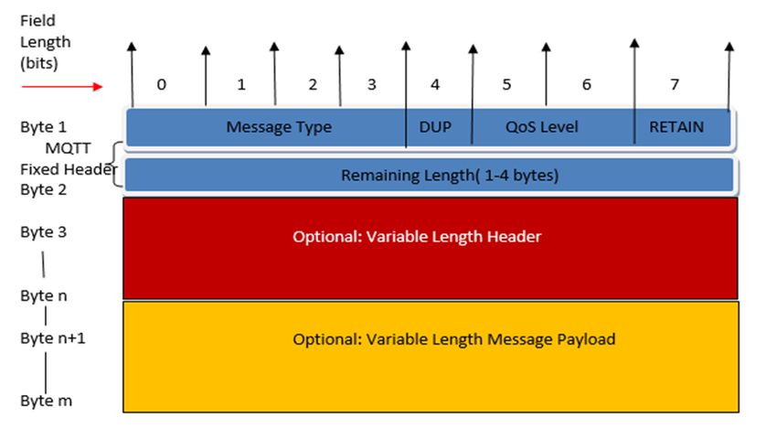
TABLE OF CONTENTS

ABSTRACT ............................................................................................................................... 2
TABLE OF CONTENTS ........................................................................................................... 3
FOREWORD ............................................................................................................................. 5
LIST OF ABBREVIATIONS AND SYMBOLS....................................................................... 6
1 INTRODUCTION ............................................................................................................ 8
 1.1 Demand of LoRaWAN ............................................................................................ 8
 1.2 The objective of thesis ............................................................................................. 9
 1.3 The approach of thesis ............................................................................................. 9
2 RELATED WORK ......................................................................................................... 10
 2.1 Related Protocol .................................................................................................... 10
 2.1.1 Advanced message queuing protocol ........................................................ 10
 2.1.2 Secure Message Queue Telemetry Transport ............................................ 11
 2.2 Related Technology ............................................................................................... 11
3 LORAWAN .................................................................................................................... 13
 3.1 LoRaWAN Technology ........................................................................................ 13
 3.2 LoRaWAN Specification ...................................................................................... 14
 3.2.1 Class A....................................................................................................... 15
 3.2.2 Class B ....................................................................................................... 15
 3.2.3 Class C ....................................................................................................... 16
 3.3 LoRaWAN Parameters .......................................................................................... 16
 3.3.1 Band channel frequencies for the EU ........................................................ 17
4 CONSTRAINED APPLICATION PROTOCOL ........................................................... 19
 4.1 CoAP Structure Model .......................................................................................... 19
 4.1.1 Messaging model ....................................................................................... 19
 4.2 CoAP Message Format .......................................................................................... 20
5 MESSAGE QUEUE TELEMETRY TRANSPORT ...................................................... 22
 5.1 MQTT Protocol ..................................................................................................... 23
 5.2 MQTT Message format ......................................................................................... 25
 5.2.1 RETAIN message format .......................................................................... 26
6 MQTT OVER LORAWAN ............................................................................................ 28
 6.1 Comparison of Protocols ....................................................................................... 28
 6.2 MQTT over LoRaWAN ........................................................................................ 30
 6.2.1 MQTT procedures over LoRaWAN .......................................................... 31
 6.3 Analysis of performance of MQTT over LoRaWAN ........................................... 33
 6.3.1 LoRaWAN transmission for MQTT ......................................................... 33
 6.3.2 CONNECT ................................................................................................ 36
 6.3.3 PUBLISH .................................................................................................. 38
 6.3.4 DISCONNECT .......................................................................................... 39
7 DISCUSSION ................................................................................................................. 41
8 CONCLUSIONS ............................................................................................................ 42
9 REFERENCES ............................................................................................................... 43
FOREWORD

This Under the Faculty of ITEE of the University of Oulu, this thesis has been prepared to
successful completion for the International Master's Degree Programme. This work is done at
the Centre for Wireless Communications research unit at The University of Oulu as a partial
completeness of master's degree requirement in ECE and the accomplishment of the thesis work
is set to measure CoAP and MQTT over the LoRaWAN . After completing all of my tasks of
this paper, I will be able to increase my practical knowledge and the theoretical knowledge. I
become familiar with CoAP, MQTT, and LoRaWAN. From my point of view, the whole works
are only possible to complete with the guidance of esteemed researchers who are working in
this diverse research unit. In my words of gratitude to both supervisor and technical supervisor
on my thesis are greatly helpful. The guidance of you at each stage made the timely
accomplishment of the work possible. Konstantin Mikhaylov (Assistant Professor), thanks a lot
for being a part of my journey, your suggestions were the appropriate directions for me. My
supervisor on the thesis, Dr. Jussi Haapola (Adjunct Professor), thanks for your encouragement
and supervision. Without your proper directions, the completion of the work was not possible
anymore. I would you like to say thanks to my friends particularly, Md Johirul Islam, Md
Sanaullah, Md. Ziaul Hoque and Famida Afroz Lopa for their company and fun during the
course of my master’s journey I will be grateful that whoever reads my thesis work many years
from now, I can appreciate the hardship and struggle you are going through. It is my own
suggestion, do not lose your hopes as there is always a bright light at the end of a tunnel.
Whereas I also faced great problems and tried to struggle to find out my exact results, and then
I was able to solve my questions and problems at the end. By exploring my own situations, I
am going to say that just stay focused and keep doing the good work. Nothing is impossible in
the thesis tasks. You have to find out your problems and solve them, as I did my works.

Oulu, Finland, July 24, 2020

Md Kamrul Hasan
LIST OF ABBREVIATIONS AND SYMBOLS

3G Third Generation
3GPP Third Generation Partnership Project
4G Fourth Generation Mobile Networks
ABP Authentication By Personalisation
ACK Acknowledgement
AES Advanced Encryption Standard
ALOHA Additive Links On-line Hawaii Area
AMQP Advanced Message Queuing Protocol
API Application Interface
AS Application Server
ASCII American Standard Code for Information Interchange
AWS Amazon Web Services
BLE Bluetooth Low Energy
BW Bandwidth
CoAP Constrained Application Protocol
CON Confirmable
CPU Central Processing Unit
CRC Cyclic Redundancy Check
CT Connection Timeout
dB Decibel
DR Data Rate
E2E Exchange to Exchange
ED End Device
ETSI European Telecommunications Standards Institute
FOpt Fields of Proficiency Testing
GW Gateway
HTTP Hyper Text Transfer Protocol
IBM International Business Machines Corporation
IETF Internet Engineering Task Force
IH Implicit Header
IoT Internet of Things
IPv4 Internet Protocol Version 4
ISM Institute for Supply Management
ITEE Information Technology and Electrical Engineering
KAT Keep Alive Time
Kbps Kilobits Per Second
KHz Kilohertz
LoRa Long Range
LoRaWAN Long Range Wide Area Network
LoWPAN Low-power Wireless Personal Area Networks
LPWA Low Power Wide Area
LPWAN Low Power Wide Area Network
LTE Long Term Evolution
LWM2M Lightweight Machine to Machine
LWT Last Will and Testament
M2M Machine-to-Machine
MAC Media Access Control
MB Megabytes
MHz Megahertz
MQTT Message Queuing Telemetry Transport
NAT Network Address Translation
NB-IoT Narrowband Internet of Things
NON Non-Confirmable
NS Network Server
OASIS Organization for the Advancement of Structured Information Standards
PHDR Physical Header
PHY Physical Layer
PL Payload
QoS Quality of service
RAM Random Access Memory
RFC Request For Comments
RL Remaining Length
RST Reset
SCADA Supervisory Control And Data Acquisition
SCTP Stream Control Transmission Protocol
SF Spreading Factor
SMQTT Secure Message Queue Telemetry Transport
TCP/IP Transmission Control Protocol/Internet Protocol
TKL Token Length
TLS Transport Layer Security
ToA Time On Air
UDP User Datagram Protocol
URI Uniform Resource Identifier
Wi-Fi Wireless Fidelity

npreamble Programmed Preamble Length
npayload Number of Payload Symbol
RS Symbol Rate
RX Receiver
Tpreamble Preamble Length
Tpacket Packet Duration
Tsym Symbol Period
+/- Plus, or Minus
1 INTRODUCTION

With the enhancement in the number of end-users and the increasing demand for machine to
machine communication use cases, it emerges that the existing communication system will soon
need a major evolution. Communication technology, especially wireless technology has
become an important part of our life, offering flexible choices based on connectivity and DRs.
To achieve long connectivity, over six miles, and optimal date rate, long-range (LoRa) devices
and long-range wide area network (LoRaWAN) protocol has some distinguished features [1].
 The LoRaWAN is a specification for wireless communication. Compared to other
technologies such as wireless fidelity (Wi-Fi), narrowband-Internet of things (NB-IoT) and
long-term evolution for machine type communications (LTE-M), LoRaWAN is more suitable
for this thesis work for a number of reasons. LoRaWAN is a newly wireless technology
intended for low-power wide area network (LPWAN) with low cost. It has low power
consumption and an optimized protocol designed for scalable wireless networks with millions
of devices. MQTT is an inconsequential publish and subscribe system where one can publish
and receive messages as a client. LoRaWAN supports long-range communication for MQTT
[28]. The MQTT protocol has much more messages but in this thesis, three messages which are
analysed with different spreading factors of LoRaWAN. Furthermore, CoAP is also one of the
most recent usage layer protocols established by the Internet Engineering Task Force (IETF)
for smart devices to link up the internet. Thus, lightweight protocol MQTT and CoAP are
expected to be deemed and used as a replacement of HTTP [3]. Lightweight protocol means
any protocol that has a leaner and lesser payload when being transmitted and used over a
network connection. It is simpler, easier and faster to manage than other communication
protocols used on a local and wide area network. These protocols are also needed for low power
consumption.

 1.1 Demand of LoRaWAN

One of the essential disruptions is brought by LoRaWAN technology to the IoT market. It is
the potential technology to spread any type of business standard from implementing privately.
It is also owned networks to subscribe connectivity to a LoRaWAN operator. LoRaWAN
technology is efficient for indoor or rural. Whereas LoRa technology is variable for indoor or
rural. Moreover, the cooperative nature of LoRaWAN has been promoting the emergence of
global open developer communities [1]. To support the remarkable demand for bandwidth, new
technology has entered the IoT field and it is called the LoRaWAN. It saturates the technology
gap of Cellular and wireless fidelity / Bluetooth low energy (BLE) based networks that require
either high power or high bandwidth or have a limited range or inability to enter deep indoor
environments. LoRaWAN technology is efficient for indoor or rural use cases in smart homes,
smart cities, buildings, smart metering, smart agriculture and logistics and smart supply chain.
Figure 1 shows the LoRaWAN position compared to the other technologies.
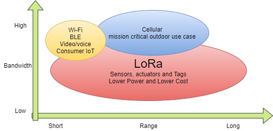
9

 Figure 1. Different technologies [4].

 1.2 The objective of thesis

For completing the objective of this thesis, it must measure the MQTT and CoAP protocols
over the LoRaWAN in an analytical way. In this thesis work, the new LoRaWAN technology
will be used as the base technology. It is known that LoRaWAN is low-power wide-area
network (LPWAN) [5]. In this work, different messages of MQTT needs to be analysed using
the various spreading factors (SFs) and payloads. Depending on the spreading factors, the
maximum payload size in Europe per message is from 55 to 250 bytes. In this case, three
messages, which are key for the MQTT uplink operation, i.e., connect, disconnect and publish
will be used for analysis. The LoRa uses the 868 MHz frequency band and this frequency is
license-exempt for usage. LoRa is also used for long-distance information transfer. The LoRa
modulation will enable to obtain up to 20 km transmission with low power. All these criteria
will be analytically discussed to obtain the concrete result. The LoRaWAN has three classes
(A, B and C) which will help to get the result in this thesis work. The result will be described
as a table at different time duration for required messages.

 1.3 The approach of thesis

In this section, the methodology of the work will be discussed. In this work, two lightweights
widely used protocols such as MQTT and CoAP have been selected. Prior to that many protocol
characteristics such as protocol key features, security, ability and comparison with other
protocols have been studied. In the comparison view, it is found out that MQTT and CoAP are
the most suitable protocols. Hence, three messages of MQTT protocols over the LoRaWAN
technology has been used for further analysis because MQTT is used for many to many
communications. An analytical study has been conducted to get time duration for different
messages of the protocols regarding the connecting, disconnecting and publishing. A complete
description about DR, SF and bandwidth (BW) can be found in my thesis work. Depending on
the DR, SF and BW total time duration of the protocol messages varies.
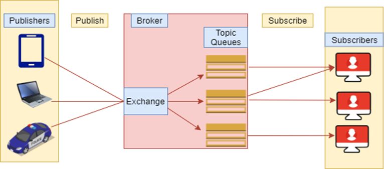
10

 2 RELATED WORK

This chapter describes the related work respective to the thesis objective. There are several
protocols which are working similarly with MQTT and CoAP protocols. To understand the
significance of the selected protocols, a deep study has been conducted about similar technology
in this work. Furthermore, LoRaWAN has also similar technologies which are described.

 2.1 Related Protocol

In this related protocol work, It has selected the advanced message queuing protocol (AMQP)
and Secure Message Queue Telemetry Transport (SMQTT) [6]. MQTT is a lightweight
protocol because all its messages have a small data footprint. Every message consists of a fixed
header two bytes, an optional variable header, a message payload. This limitation is to 256
megabytes (MB) of information and quality of service (QoS) level.

 2.1.1 Advanced message queuing protocol

Advanced message queuing protocol (AMQP) is called an open standard subscribe/publish type
protocol. AMQP is a new Organization for the Advancement of Structured Information
Standards (OASIS) standard and it runs over the transmission control protocol (TCP) [6].
Although AMQP has secured some ground inside the information communication technology,
it is still quite limited on the internet of things (IoT) industry. Furthermore, the AMQP
specification defines such elements as message orientating, queuing, routing (including point-
to-point and publish-and-subscribe), dependability and security. It is probably the only protocol
feasible for an end-to-end application with such models as weighty industrial machinery or
Supervisory control and data acquisition (SCADA) systems, wherever the devices and the
network are significantly efficient as a rule [7]. However, the most crucial different standards
are that the broker is separated between exchange and queues, as shown in Figure 2.

 Figure 2. AMQP architecture [8].

 The AMQP is an application layer protocol. The publish/subscribe (pub/sub) is meant to
decouple the client that sends as a publisher from the client or clients that receive as subscribers.
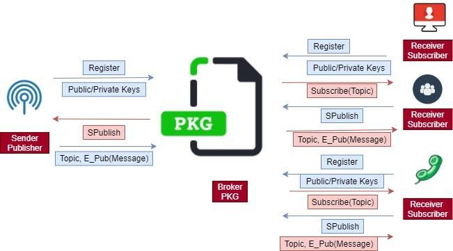
11

The client is any device of AMQP. The connection of a publisher and a subscriber is controlled
by the broker. The broker is a server which receives all messages.

 2.1.2 Secure Message Queue Telemetry Transport

SMQTT stands for Secure Message Queue Telemetry Transport which uses encryption based
lightweight attribute-based encryption. The most important advantage of utilizing such
encryption is the broadcast encryption feature, in which one message is being encrypted and
delivered to several other nodes, which is very common in IoT applications [25]. SMQTT is
intended only to enrich the MQTT security features. Figure 3 [6] shows SMQTT protocol [7].
Figure 3 is described in detail in below how sender publisher and receiver subscriber are
communicating through the broker.

 Figure 3.Secure MQTT protocol.

 The broker receives all messages from different clients. After receiving the messages, it is
used to route the proper destination clients. There are some public and private messages that
are received. The broker can receive all clients’ messages.

 2.2 Related Technology

In this chapter, it has made a comparison of different related technologies. Among them, here
is selected LoRaWAN technology for the thesis work and Table 1 shows in addition
Narrowband Internet of Things (NB-IoT) and Long Term Evolution (LTE-M). It just
highlighted the parameters of all the technologies. These are low power consumption
technologies.
12

Table 1. Different low power technologies [9]
 Technology
 Parameters LoRaWAN NB-IoT LTE-M

 Bandwidth 125 kHz 180 kHz 1.4 MHz
 Battery Life 15+ years 10+ years 10 years
 Coverage 165 dB 164 dB 156 dB
 Throughput 50 kbps 60 kbps 360 kbps
 Security AES 128 bit 3GPP (128 to 256 3GPP (128 to 256
 bit) bit)

 NB-IoT is also a low power wide area (LPWA) technology used to support a wide range of
new IoT services and devices. It also significantly enhances the power consumption of user
devices, spectrum efficiency and system capacity, especially in deep coverage. LTE-M is also
a type of low power wide area network radio technology standard. The power consumption of
LoRaWAN is less compared to NB-IoT and LTE-M. While it consumes less power, LoRaWAN
also gives a longer battery life compared to LTE-M and NB-IoT (15+ years compared to 10+
years). According to the above table, the battery life is better than LTE-M and NB-IoT. The
coverage of LoRaWAN is better than other technologies [9].
13

 3 LORAWAN

The LoRaWAN has some specifications making it a long-range, low power wide area
networking protocol [2]. It is designed for connecting battery operated ‘things’ to the internet
in national, regional or global networks. The key targets are IoT requirements for such as bi-
directional communication, end-to-end security, mobility and localization services [1]. Low
power wide area (LPWA) networking technology is the long-range communication, which
empowers new forms of services. There are several existing solutions for LPWA among which
LoRaWAN is unquestionably the most highly adopted one [10]. It ensures pervasive
connectivity in outdoor IoT applications while maintaining network configurations and
management simple [10]. LoRaWAN architecture defines an end to end data transfer solution,
as illustrated in Figure 4 below. The end devices(EDs) are basically several types of sensors
that communicate with LoRaWAN gateways (GWs) using the LoRa physical layer protocol
mainly on sub-GHz license-exempt bands such as 915MHz in USA, 868MHz in EU, and
470MHz in China [38].

 Figure 4. LoRaWAN solution architecture [15].

 As stated by Figure 4, several components are defined in a LoRaWAN as end device(ED),
gateways(GWs), network server and applications. The GWs perform with the EDs by using
LoRa and LoRaWAN technologies. GWs send out the LoRaWAN frames from the EDs to a
network server which is used as a back-haul interface with higher bandwidth typically Ethernet,
3G/4G [6]. The definition of LoRaWAN GW being as "one distributed antenna, common to all
networks" strengthens GW like a physical layer device with an inactive role in the overall
network [15]. LoRaWAN requires network server (NS) and an application server (AS) and this
idea can initially cause a little uncertainty. The AS hosts the applications. Such a NS is needed
because GWs can be considered "dumb" – sending all sensor data with a small amount or no
intelligence applied to what is sent [38].

 3.1 LoRaWAN Technology

Theoretically, the LoRaWAN specification contains three major components, such as physical
layer (PHY), the link layer and the network architecture [34]. The physical and link layers
specify the communication between a GW and an ED. LoRaWAN network is deployed in a star
topology where the GW relay data message between the ED and the network server. The
14

communication in the middle of an end node and GW are bidirectional. LoRaWAN consists in
different layers, a media access control (MAC) layer is one of them and it has been added to
regulate and extend the LoRa physical communication layer on top of the LoRaWAN
specification but below the application layer [16]. This MAC layer is known as the LoRaWAN
specification. The specification is public sourced, and it is adopted by the LoRa Alliance. The
LoRaWAN protocol also consists of a key wireless network features such as adaptive data rate
optimization, quality of service, exchange to exchange (E2E) encryption, security and other
advanced communication applications [12]. It is a new technology, remote and spread-spectrum
modulation method. It permits sending data at very low data rates for very long ranges. The
LoRaWAN modulation and low data-rate (down to few bytes per second) leads to very low
receiver sensitivity (down to -136 dBm). The maximum output power of +14 dBm means very
large link budgets; up to 165 dB [9]. It means more than 22 km (13.6 miles) in line of sight
(LOS) links and up to 2 km in non-line of sight (NLOS) links in the urban environment (going
through buildings) [13].

 3.2 LoRaWAN Specification

The LoRaWAN network protocol has a special specification which is enhanced for battery
powered EDs. LoRaWAN networks typically maintain GWs relay messages between EDs and
a central NS. The NS can route the packets from each device of the network to the related AS.
So the LoRaWAN has three classes which are described below in Figure 5 [14]. The figure
shows different classes and other layers.

 Figure 5. LoRaWAN classes [32].

 In the MAC options of Class A, when the uplink packet of end nodes, two downlinks are
scheduled to open to deliver a downlink packet. The Class A is the most energy-efficient,
however, it has the highest latency [32]. Class A has the basic class implementation in every
LoRa ED, and it aims applications with low-rate downlink data. It is also confirmed low energy
consumption and corresponds to low powered devices
15

 3.2.1 Class A

In Class-A, EDs of allowing for bi-directional communications. Each EDs uplink transmission
is supported by two short downlinks receive windows. The slot of the transmission scheduled
by the ED, which is based on its own communication, requires a small variation which is based
on an arbitrary time basis (ALOHA-type of the protocol). In class A, there are physical message
formats which distinguish between uplink and downlink messages.
Uplink Messages: These messages are sent by EDs to the NS and relayed by one or many
gateways. The uplink messages make use of the LoRa radio packet explicit mode in which the
LoRa physical header (PHDR) combined with a header cyclic redundancy check (CRC)
(PHDR_CRC) are contained. Here integrity of the payload is covered by a CRC. The physical
header Cyclic Redundancy Check (PHDR_CRC), PHDR and payload CRC fields are put in by
the radio transceiver [14]. Table 2 shows the uplink PHY structure.

Table 2. Uplink PHY structure [14]
 Preamble PHDR PHDR_CRC PHYPayload CRC

 3.2.1.1 Receive Windows

Each uplink transmission of the ED opens two shorts receives windows. The receive windows
are RX1 and RX2. The receive window start times are specified using the end of the
transmission as a reference, as shown in Figure 6.

 Figure 6. End devices receive slot timing [14].

 3.2.2 Class B

In Class B, EDs also allow for more receive slots compared to the Class A random receive
windows. Here Class B devices must open extra receive windows at scheduled times. At the
scheduled time, the ED opens it receives window and it also receives a time-synchronized
beacon from the GW. EDs of Class B support for a network. All the GWs synchronously
broadcast a beacon, delivering a timing reference to the EDs. According to this timing
reference, the EDs which can periodically open receive windows, hereafter is called “ping
slots”. The “ping slots” can be used by the network infrastructure to initiate a downlink
communication. A network is begun downlink using one of these ping slots is named a “ping”.
The GW selected to initiate this downlink communication is chosen by the NS based on the
signal quality signs of the last uplink of the ED. Figure 7 of beacon reception slot and ping slots
illustrate below [14].
16

 Figure 7. Beacon reception slot and ping slots [14].

 3.2.3 Class C

EDs of Class C almost always open received windows. The receive windows are closed during
the transmission. In Class C, ED will use more power to work than Class A or Class B, but it
recommends the lowest latency for server and ED communication. Class C devices implement
the similar two receive windows as Class A devices. However, they do not close the RX2
window until they need to send again. So, they may well receive a downlink in the RX2 window
at nearly any time, with downlinks sent for the purpose of ACK transmission or MAC
command. In Figure 8 shows in Class C ED reception slot timing.

 Figure 8. Class C end device reception slot timing [14].

 3.3 LoRaWAN Parameters

With the intention for support, the identification of LoRaWAN channel plans referenced by
other specification documents and the table below offer a quick reference of common name and
channel plans listed for every formal plan name. Table 3 shows the regional parameter common
names.
17

Table 3. Regional Parameter Common Names [41]
 Channel Plan Common Name
 EU863-870 EU868
 US902-928 US915
 CN779-787 CN779
 EU433 EU433
 AU915-928 AU915
 CN470-510 CN470
 AS923 AS923
 KR920-923 KR920
 IN865-867 IN865
 RU864-870 RU864

According to the European channel plan, this thesis works to select EU 868.

 3.3.1 Band channel frequencies for the EU

This section operates to the EU region where the ISM radio spectrum use is defined by the
European Telecommunications Standards Institute (ETSI). For accessing the physical medium,
the ETSI regulations require some restrictions such as the maximum and the maximum time
can transmit per hour. There is no limitation for a dwell time of the EU863-870 PHY layer. The
TxParamSetupReq MAC command is not implemented in EU863-870 devices. The following
encoding is applied for Data Rate (DR) and ED EIRP (TXPower) in the EU863-870 band.
EU863-870 TX Data rate Table 4 is shown in below.

Table 4. EU863-870 TX Data rate table [41]
 Data rate (DR) Configuration Indicative physical
 bit rate [bit/s]
 0 LoRa: SF12 / 125 kHz 250
 1 LoRa: SF11 / 125 kHz 440
 2 LoRa: SF10 / 125 kHz 980
 3 LoRa: SF9 / 125 kHz 1760
 4 LoRa: SF8 / 125 kHz 3125
 5 LoRa: SF7 / 125 kHz 5470
 6 LoRa: SF7 / 250 kHz 11000

 So LoRa has multiple bandwidths such as 125 kHz, 250 kHz and 500 kHz. The 500 kHz is
not used in the EU. In EU863-870, the maximum MAC Payload size length (M bytes) is
provided by the following Table 5. It is obtained from the limitation of the PHY layer dependent
on the efficient modulation rate used to consider a possible repeater encapsulation layer. In
maximum application, payload size in the absence of the non-compulsory fields of proficiency
testing (FOpt) control field (N) is also provided for information only. The value of N may be
tinier if the FOpt field is not clear: Table 5 illustrates the EU863-870 maximum payload size
(repeater compatible).
18

Table 5. EU863-870 maximum payload size (bytes) [41]
 Data rate (DR) M(bytes) N(bytes)
 0 59 51
 1 59 51
 2 59 51
 3 123 115
 4 230 222
 5 230 222
 6 230 222

 If the end device will never function with a repeater then the maximum application payload
length in the non-appearance of the optional FOpt control field will be.

Table 6 shows EU863-870 maximum payload size (not repeater compatible).

Table 6. EU863-870 maximum payload size(bytes) [41]
 Data rate (DR) M(bytes) N(bytes)
 0 59 51
 1 59 51
 2 59 51
 3 123 115
 4 250 242
 5 250 242
 6 250 242
19

 4 CONSTRAINED APPLICATION PROTOCOL

The Constrained Application Protocol (CoAP) is a particular web transfer protocol for use with
constrained networks and constrained nodes in the IoT. It is used for machine-to-machine
(M2M) applications, for example, smart energy and building automation. It is improved as an
Internet Standards in the document, RFC 7252 [21]. It has been projected to last for years still
there are some difficult issues. According to the architectural view, such as hypertext transfer
protocol (HTTP), CoAP is a document transfer protocol. The HTTP together with CoAP is
designed for the demands of constrained devices, whereas CoAP packets are far smaller
compared with the HTTP TCP protocols. CoAP is constructed to inter-manage with HTTP [17].

 4.1 CoAP Structure Model

The CoAP communicating model and HTTP are a client/server model and are comparably the
same. CoAP consists of a two-layers structure which is illustrated below. The first message
layer is called the bottom layer and it is designed to an agreement with the user datagram
protocol (UDP) and asynchronous switching. In addition, the communication method is
concerned with the request/response layer and dealt with the request/response message [18].
With the standardizing of CoAP, for instance, Lightweight Machine to Machine (LWM2M)
currently uses CoAP over UDP as a transport. Support for CoAP over TCP allows it to report
the issues above for specific placements and to protect investments in current CoAP
applications and deployments [20]. Figure 9 shows the model of the CoAP structure.

 Figure 9. Basic structure model of CoAP [21].

 4.1.1 Messaging model

In this layer, there are four types of messages which are called CON (confirmable), NON (non-
confirmable), ACK (Acknowledgement) and RST (Reset). These four types of messages are
described reliable message and unreliable message transport [18].
 The reliable message transport system: It must retransmit while waiting for getting ACK
with a similar message ID, applying default timeout and reducing calculating time
exponentially while CON is being transmitted. If any receiver is unable to process the message,
it will be responded with the replacement of ACK with RST. The reliable message transport is
illustrated in Figure 10 below [3].
20

 Figure 10. The reliable message transport [3].

 The unreliable message transport-system: Here, the message transporting system is
NON-type. If it contains a message ID, it will not need to be ACKed to oversee in case of re-
transmission. The unreliable message transport-system is illustrated in Figure 11.

 Figure 11. The unreliable message transport [3].

 4.2 CoAP Message Format

In CoAP message format, there are four bytes of binary fixed-length header. The format of
CoAP messages is encoded in an easy binary way. Every message is included with a specific
Message-ID. Message-ID is applied to distinguish duplicate packets and ensure reliability.
Dependability is provided by publishing a message as CON. A Confirmable message is re-
communicated, applying a default timeout and exponential back-off between re-transmissions
until the receiver transmits an ACK message with a similar Message-ID. Figure 12
demonstrates the CoAP message format. The description is also discussed below.
21

 Figure 12. CoAP message format [19].

Version (Ver): Here the 2-bit integer is unsigned, and the CoAP version number is indicated.
It should be set to 1 (01 binary). Additional values are held in reserve for future versions.
Messages with undetermined version numbers must be mutely unheeded.
Type (T): 2-bit unsigned integer. In this section, the messages are indicated by the type of
Confirmable (0), Non-confirmable (1), Acknowledgement (2), or Reset (3)
Token Length (TKL): This section is discussed about 4-bit unsigned integer. It is showing the
length of the variable-length Token field (0-8 bytes). The reservation lengths are 9-15 which
should not be sent and need to be dealt with as a message format error.
Code: In this 8-bit unsigned integer, the code is divided into a 5-bit detail (least significant bits)
and 3-bit class (most significant bits). It is known as "c.dd" wherever "dd" are two digits from
00 to 31 for the 5-bit subfield, and "c" is a digit from 0 to 7 for the 3-bit subfield. The class can
signify a request (0), a success response (2), a client error response (4), or a server error response
(5). (All other class values are reserved).
Message-ID: In the network byte order, the message-ID is unsigned 16-bit integer. Message
duplication applies for detection and it is also matched with the messages of the type
ACK/Reset to the messages of type Confirmable/Non-confirmable.
Token: The Token is applied to match up a response with a request. The token value maintains
a sequence which ranges from 0 to 8 bytes. Every Single request carries a client-created token
that the server must echo (without modification) in any subsequent response.
Options: A list with one or more options might be included with both requests and responses.
For instance, the URI in an application is transferred in several options and metadata that would
be kept in an HTTP header in HTTP is provided as options as well [20].
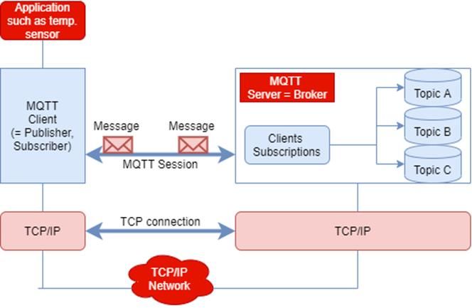
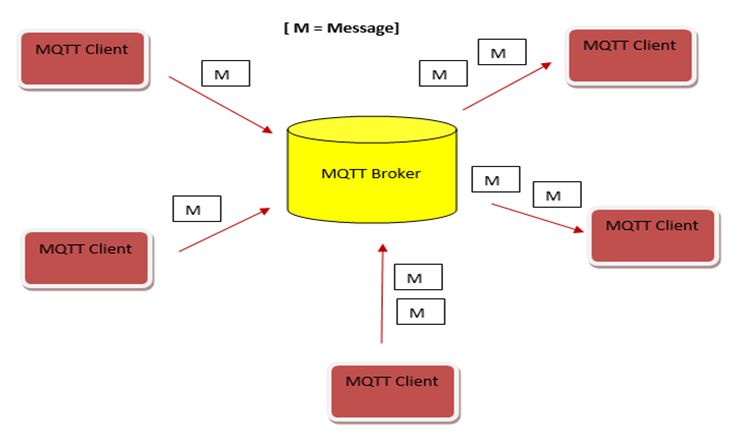
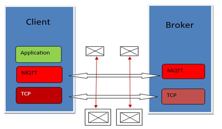
22

 5 MESSAGE QUEUE TELEMETRY TRANSPORT

MQTT(Message Queue Telemetry Transport) is a publish/subscribe, extremely simple and a
lightweight messaging protocol that allows embedded devices with restricted resources (CPU,
RAM, battery, etc.) to operate asynchronous communication on a constrained network [22]. It
is called the machine to machine(M2M) connectivity protocol [43]. The MQTT protocol is
designed for low-bandwidth, constrained devices, and untrustworthy networks [44]. The model
principles are to reduce network bandwidth and device resource requirements whereas, also
attempting to make sure reliability and some degree of assurance of delivery. These principles
are also used to create the protocol standard of the outgoing "machine-to-machine" or "Internet
of Things" world for connected devices. These devices are used for mobile applications and in
this case, the bandwidth and battery power are at a premium. As its name indicates, it is well-
matched for the telemetry data transport as sensors data. It can also be used for other purposes,
as example- the Facebook Messenger application for smartphones uses the MQTT protocol for
the messages exchanged in the middle of the clients [23]. The architecture of MQTT is depicted
in Figure 13.

 Figure 13. Simple MQTT architecture of broker and client [22].

 Generally, the MQTT protocol with a network contains lots of clients (up to ten thousand
devices) and a server known as "broker". Every single client connects to the broker running its
own unique identifier (client ID). Client connections are managed with the role of the broker to
transfer messages between them. Moreover, the responsibility is kept by the broker for handling
any message persistence and the broker can transmit them to the clients that were for the
moment disconnected but returned online; this feature is named "retain message". A client
ought to send a keep-alive message regularly to the broker to maintain the connection alive
when it is in idle state (not pulling or pushing messages) for a long time. If not, the broker
dismisses the connection after a timeout. Fundamentally, a connection timeout is computed by
the following equation.

 = 1.5⸱ , (1)
23

where CT is the connection timeout and KAT is the keep-alive time. Along with the equation,
the connection time is proportionate to the keep-alive time. Every part of the architecture is
based on TCP/IP, which is a suite of communication protocols used to interconnect network
devices. Every message switched between clients is packaged inside a TCP packet. Figure 14
shows the TCP packets where messages are wrapped inside. TCP/IP is called a set of
standardized rules that permit computers to communicate on a network such as an internet [22].

 Figure 14. MQTT is based on TCP/IP [22].

 5.1 MQTT Protocol

MQTT is one of the good commonly employed protocols in IoT projects. This protocol is a
lightweight protocol and it is also simple to implement in software and better-speed data
transmission. The MQTT protocol is very fast in delivering messages by using a
messenger/WhatsApp message [23]. The communication model is asynchronous with
messages. It decouples the data producer (publisher) and data consumer (subscriber) through
topics. MQTT is a simple protocol, aimed at low complexity, low footprint implementations
and low power [24]. It is going on connection-oriented transport (namely TCP). While MQTT
has been intended to be easy to implement, it yet comprises relatively complex protocol logic
for controlling connections, subscriptions and the numerous qualities of service levels related
to message delivery. According to the QoS, the MQTT protocol delivers application messages
on three levels. The delivery protocol is aimed exclusively to delivery of an application message
from senders to receivers [25]. The MQTT protocol also has some core elements, such as
clients, servers (=brokers), sessions, subscriptions and topics [24]. The core model of MQTT is
shown in Figure 15.
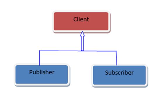
24

 Figure 15. MQTT core model [24].

 Therefore, clients are subscribed towards topics on the way to publish or receive messages.
Hence subscriber and publisher are exclusive roles of a client shown in Figure 16.

 Figure 16. Client combination of publisher and subscriber [24].

 Server topics are employed to receive subscriptions from clients and receive messages from
clients and these are also forwarded depending on client's subscriptions to create an interest in
the clients. Theoretically, topics are known as message queues. Topics improve the
publish/subscribe form for clients. Rationally, topics let clients exchange information with
defined semantics. Figure 17 shows the exchanging information.

 Figure 17. Topic with message queues [24].
25

 5.2 MQTT Message format

A mandatory fixed-length header which is two bytes, an optional message-specific variable
length header and message payload is contained with the MQTT messages. The optional fields
generally make protocol processing difficult. Though MQTT is optimized for bandwidth-
constrained and unreliable networks (typically wireless networks), Whereas the optional fields
are employed to decrease data transmissions quickly. MQTT is a protocol based on a binary
and the control elements are binary bytes and not text strings [26]. MQTT uses a command and
command acknowledgement format. The description of MQTT usage is explained in Figure
18 for network byte and bit ordering [24]. Table 7 also shows the fixed header fields in a short
description.

 Figure 18. MQTT uses network byte and bit ordering [24].
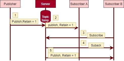
26

Table 7. The overview of fixed header fields is described by the table [26]
 Message fixed header Description / Values
 field

 0: Reserved 8: SUBSCRIBE

 Message Type 1: CONNECT 9: SUBACK

 2: CONNACK 10: UNSUBSCRIBE

 3: PUBLISH 11: UNSUBACK

 4: PUBACK 12: PINGREQ

 5: PUBREC 13: PINGRESP

 6: PUBREL 14: DISCONNECT

 7: PUBCOMP 15: Reserved
 Matching message flag. Shows to the receiver that this the
 DUP message may have meanwhile acceptance.
 1: Server (broker) or client re-delivers a PUB, REL,
 PUBLISH, SUBSCRIBE or UNSUBSCRIBE message
 (duplicate message)
 Signifies the level of distribution assurance of a PUBLISH
 message.
 QoS Level 0: At-most-once delivery, no guarantees, «Fire and Forget».
 1: At-least-once delivery, acknowledged delivery.
 2: Exactly once delivery.
 Further details see MQTT QoS.
 1: According to the order, the server to hold the last received
 RETAIN PUBLISH message and transmit it as a first message to the
 new subscriptions.
 Further details see RETAIN (keep the ending message).
 Turns the number of remaining bytes in the message, i.e. the
 Remaining Length length of the payload(optional) and the variable length
 header (optional).
 More details also see Remaining length (RL)

 5.2.1 RETAIN message format

When RETAIN=1, the server is instructed in a PUBLISH message to keeping the message.
After subscribing to the topic, a new client with the server sends the retained message. Typical
27

application scenarios: changes are published for the clients in the data, so subscribers obtain the
very last known good value. Example: Subscribers take the last known temperature value from
the temperature data topic. RETAIN=1 signifies to subscriber B and in this situation, the
message may possibly be published sometime in the past. Figure 19 shows the RETAIN
message format.

 Figure 19. Retain = 1, publisher [24].

 In the Retained message, MQTT broker stores that message and sends it to any new
subscriber. The messages which will be used in implementation are CONNECT,
DISCONNECT and PUBLISH. These messages are needed to enable delivery of the uplink
data for which the LoRaWAN is optimized. The connection of MQTT always exist between a
client and a broker. Clients are never able to connect to each other directly. For initiation, the
client sends a CONNECT message to the broker and the broker responds with a CONNACK
message and a status code. In this case, both client and broker need a TCP/IP stack. When the
connection is established, then the broker keeps it open until the client sends a disconnect
command or the connection break [27].
28

 6 MQTT OVER LORAWAN

In this section, it is needed to specify how the key MQTT & CoAP messages can be sent over
LoRaWAN class A MAC. It is needed to be mindful of the PHY layer limitations and MAC
procedures and what are the fundamental performance limits associated with this. The MQTT
has some limitations which are described below.
 The function of MQTT: MQTT sends a command to output and receives a subscribe
message. It is considered a publish and subscribe system where I can publish and receive
messages as a client. It also maintains a simple communication between multiple devices.
MQTT is low bandwidth and a simple messaging protocol which is designed for constrained
devices. It allows me to send commands to control outputs, read and publish data from much
more and sensor nodes. Consequently, it creates easiness to establish communication between
multiple devices [28].
 It operates over TCP: TCP has more processing and memory powered protocol than many
of the lightweight, power constrained IoT devices. TCP needs more handshaking to set up
communication relations before any messages can be replaced. This increases communication
and times wake-up, which can affect long-standing battery consumption. However, connected
devices of TCP tend to keep sockets open for each other with a persistent session. The power
and memory requirements are also added here.
 A centralized broker can limit scale: The scalability can be affected by a broker as there
is extra overhead for each device connected to it [48].

 6.1 Comparison of Protocols

MQTT protocol is the many to many protocols for passing messages. It stores data from
numerous electronic devices and maintains remote device monitoring. It runs over TCP that
means it supports event-driven message exchange through wireless networks.
 Whereas the CoAP is a one-to-one protocol for transferring messages between server and
client. This protocol is used to transmit a request to the application endpoints and send back the
reply of services and resources in the application.
 The AMQP protocol works at point-to-point for transporting message between two network
processes. It also uses TCP/IP protocol to transfer message in between networks. AMQP
contains three separate elements, namely Exchange, Message Queue and Binding. Typically, it
tracks message while a message is sent from server to destination users. The comparisons of
MQTT, CoAP and AMQP also described in Table 8 below [46].
29

Table 8. The analysis of messaging protocols for IoT Systems: MQTT, AMQP and CoAP
 Specification MQTT AMQP CoAP
 Architecture Client/Broker Client/Broker or Client/Server or
 Client/Server Client/Broker
 Abstraction Publish/Subscribe Publish/Subscribe or Request/Response or
 Request/Response Publish/Subscribe
 Header Size 2 Byte 8 Byte 4 Byte
 Message Size Small and Undefined Negotiable and Small and Undefined
 (up to 256 MB Undefined (normally small to fit
 maximum size) in single IP
 Datagram)
 Transport TCP (MQTT-Sensor TCP, SCTP (Stream UDP, SCTP (Stream
 Protocol Network) can use Control Control
 UDP) Transmission Transmission
 Protocol) Protocol)

 Moreover, machine-to-machine (M2M) communication protocol is used to manage remote
application based on IoT devices. M2M protocol typically communicates between two
machines which are predominantly cost-effective. It keeps the self-monitoring of machines and
permits the systems to adjust according to the changing environment. Additionally, the Figure
20 conveys the relative difference of these messaging protocols which are based on their usage
in accreditation and M2M/IoT from standard organisations.

 Figure 20. M2M/IoT usage vs standardisation [46].

The above graph shows that MQTT has been used by a large number of organisations. MQTT
is described as a M2M protocol and has been supported and run by a large number of
organisations such as Facebook, IBM, Cisco, Eurotech and Amazon Web Services (AWS) [46].
 It is an efficient way to communicate from one system to many systems with some feedback
from the recipient. So, the MQTT protocol has many-to-many communication protocol with
ACK while the AMQP sends a point-to-point communication system with tracking. However,
30

CoAP sends a response from receiver to sender. So, comparing AMQP over CoAP, AMQP
tracks the massage until it reaches, so it is not efficient compared to CoAP.
 The MQTT and CoAP both are useful as IoT protocols having some fundamental
differences. The MQTT is a many-to-many communication protocol where the messages are
passed between many clients through a central broker. However, CoAP primarily maintains a
one-to-one protocol for transferring state information between server and client. MQTT
communicates using publish or subscribe method while Request-Response method is used by
CoAP. It commonly uses TCP protocol which is slower but reliable transfer typically used at
Email and Web browsing. On the contrary, the CoAP mainly uses UDP protocol which is faster
and nonguaranteed transfer. In this case, MQTT is connection-oriented and acknowledgement-
based protocol whereas CoAP is connectionless without acknowledgement-based protocol. The
MQTT uses asynchronous transmission while CoAP uses both synchronous transmission and
asynchronous transmission. So MQTT protocol application reliability level is more than the
CoAP protocol [46].
 In this thesis work, an MQTT protocol is selected which is connection-oriented and ACK-
based protocol. It is also quite a reliable protocol which makes sure data transfer from clients
to the broker is based on acknowledgement. So, to transfer message from one broker to many
clients; MQTT protocol is needed. That is why It is used for analysis as it works as a reliable
ACK-based protocol which transfers message many-to-many.

 6.2 MQTT over LoRaWAN

The goal of the analysis in this thesis is, how MQTT protocol runs over the LoRaWAN. MQTT
is a message transmission protocol based on the lightweight, publish-subscribe network model.
Here, it goes over the TCP/IP and provides lossless, ordered and bi-directional connections
[29]. In this case, MQTT which message will be sent from ED to GW and finally MQTT server.
The choices are some of the most popular protocols such as MQTT, HTTP, AMQP, and CoAP.
All of them are suited for a specific scenario and environment. Well it has been selected the
MQTT protocol because it serves the purpose better compared to others for this application. It
delivers messages with a lower delay when the packet loss rate is low [30]. Figure 21 illustrates
the MQTT connection over the LoRaWAN [29].

 Figure 21. MQTT connection over the LoRaWAN [29].

 The MQTT can use publish-subscribe message model to provide one-to-many message
publish and decoupled applications. Three QoS levels are existing in MQTT as mentioned. “At
most once”- the delivery message at most once situation, where messages can arrive
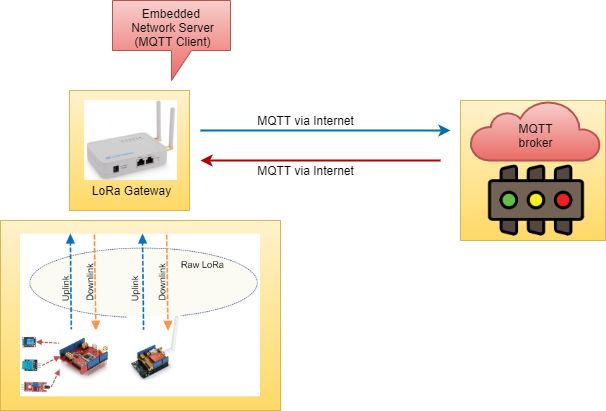
31

corresponding to the best works of the underlying TCP/IP network. “At least once”- the delivery
message in the at least once, a message is delivered at least one time to the receiver, but
duplicates may occur. “Exactly once”- the delivery message occurs exactly once. Small data
amounts are transmitted with a small header, a fixed length of only two bytes and protocol
exchanges are minimized to decrease network traffic. The network connection runs over
TCP/IP. MQTT protocol is thoroughly applied into the IoT solutions with very “Low-
bandwidth and unreliable links” [29]. It has two transmission ways described below.
For Uplink: The sensor transmits MQTT data from LoRaWAN wireless to LoRaWAN GW.
The GW will deal with these data and forward to a distant MQTT broker via the Internet.
For Downlink: A topic is subscribed by the ED in the MQTT broker, existing the update on the
topic, the gateway will realize and transmit the MQTT data to Local LoRaWAN network
[31]. The network structure for MQTT forwarding is depicted in Figure 22 below.

 Figure 22. Topology for MQTT connection [31].

 Sensor nodes are used in LoRaWAN, and they do not have to trouble with MQTT or with
the MQTT Server. They just apply send/receive MQTT data to/from the LoRaWAN gateway.
The LoRaWAN unpacks MQTT data to the gateway. The GW sends MQTT data through the
TCP to NS. The MQTT broker is unable to communicate with the local LoRaWAN network
[29].

 6.2.1 MQTT procedures over LoRaWAN

The LoRaWAN device is one of the critical parts of this system. The LoRaWAN, a MAC -layer
protocol that is implemented as a star-of-star topology to regulate LoRaWAN devices [35].
LoRaWAN device collects the data of activity and location information, then sends them to the
LoRa GW. In this system, the device works in Class A mode, which is the lowest power
consumption mode in LoRa systems [36]. Later the application server (AS) transmits the
message to MQTT broker. In this case, MQTT protocols higher in the protocol stack can also
be applied for the communication among GW, NS, and the AS. Figure 23 illustrates MQTT
over LoRaWAN.
32 Figure 23. MQTT message over the LoRaWAN [36]. According to Figure 24, a sequence diagram is drawn to show how messages are transferred from the ED to the MQTT server. In this section, it has chosen an elaborate lightweight publish- subscribe IP protocol (i.e. a LoRaWAN payload can be sent to many MQTT clients simultaneously each serving a different purpose or application) [36]. Likewise, secure one-to- many communication, UDP is more vulnerable to spoofing and denial of service attacks. In this thesis work, I have selected the MQTT protocol for this sequence diagram. The LoRaWAN solution sequence is explained below in Figure 24. Figure 24. LoRaWAN solution sequence diagram. To give an example, an ED is expected to send sensor data (temperature and humidity), (1 in hexagon shape as mention in state diagram) through LoRaWAN network to an application server so that a user can monitor an application (4 in hexagon shape as mention in state diagram). An experiment assuming a use case scenario where a user wants to turn ON / OFF a bulb resided at ED (1) from a remote position with an application (4). "ON" and "OFF" are the bulb state as payload where the payload size is 2 bytes (for two characters in “ON”) or 3 bytes (for three characters in “OFF”), respectively. Experiment setup also includes connect, publish; and disconnect which is discussed in detail in 6.3.2 – 6.3.4. Assuming ED has three bulbs: bulb1, bulb2 and bulb3. "ON" or "OFF" is their payload where payload size is two or three respectively. All these have same request pattern, but here bulb1 request pattern is shown in above Figure 24. LoRaWAN GW sends the message (received from end device) to the LoRaWAN network server (marked 2 as shown in the above figure). The network server reverses the prior process (i.e convert hex to ASCII of the message) and sends the newly available data to the application server (marked as 3 on the figure).
33 Finally, MQTT server (broker) sends the received message “bulb1, bulb2 and bulb3” to the application (marked as 4 on the figure). Here, steps 5 – 8 are illustrated the response happening whereas steps 1 – 4 are requested in the model. In the response, encoding and decoding takes place into step 6 and 8, respectively while these takes place into step 1 and 3 in the request cycle. The simulation is done in MQTT [40]. 6.3 Analysis of performance of MQTT over LoRaWAN The data transmission protocol analysed in this thesis provides an MQTT over LoRaWAN operated. The MQTT client publishes a message on a specific topic. The message is delivered by the MQTT broker to all the clients subscribed to that topic and sends the command via LoRa to the end node. The LoRaWAN, a MAC layer protocol that is implemented as a star-of-star topology to regulate LoRa devices. Class A in MAC layer is selected for analysis performance where ED sends an MQTT message to the gateway. Finally, for the EDs of Class A, each uplink transmission is followed by the two receive windows (RX1 and RX2) as this is illustrated in Figure 25. Figure 25. LoRaWAN class A ED uplink transmission phases [42]. According to the above Figure and following the common practice [41], the RECEIVE_DELAY 1 is 1s for RX1 window and RECEIVE_DELAY 1 is 2s. 1s and 2s are default value both of the windows (RX1 and RX2) [42]. ). Here RX1DROffset default value is zero; that is why there is nothing to make delay. Where RX2 uses a fixed data rate and frequency [41]. 6.3.1 LoRaWAN transmission for MQTT In terms of LoRa, the amount of spreading code applied to the original data signal is referred as the spreading factor (SF). There are six spreading factors (SF7 to SF12) in LoRa modulation. The LoRaWAN uses spread factors from 7 to 12. The SF7 is the shortest time on-air, and the SF12 will be the longest. Here SF = 6 is a different use case for the highest data rate transmission possible with the LoRa modem. When it is used the lower range of SF values, then the data rate is very high, and air-time is short. So, SF is the key variable of the quality of the service. Higher SFs means longer range but limits the QoS. The DR in achievable communication can be calculated from the bandwidth BW (Hz), coding rate (CR), and the SF. Two bandwidths are used (125kHz and 250kHz) in LoRa [41]. According to different locations LoRa uses different bands. Depending on TCP, MQTT uses TLS (Transport Layer Security) for data encryption and secure communication [36]. All the data are extracted through the application service by deploying a simple application interface (API). In this case, the MQTT broker is used to obtain
You can also read