ANALYZING AUTOMOTIVE RADAR SIGNALS WITH AN OSCILLOSCOPE - Automotive radars on the test bench
←
→
Page content transcription
If your browser does not render page correctly, please read the page content below

ANALYZING AUTOMOTIVE RADAR SIGNALS WITH
AN OSCILLOSCOPE
Automotive radars on the test bench

eBook | Version 01.00
2
SEEING THE WORLD THROUGH SENSORS
Driverless cars are virtually unique in symbolizing the power of future     The number of radar sensors per vehicle rises with each level of
technologies and digitalization to alter our everyday lives. Connected,     automation. Highly automated driving naturally places high demands on
automated driving holds the promise of significantly higher road safety     the technology. The latest systems operate in the microwave region to
and convenience. However, trusting an autonomous vehicle is a big step      determine the range, velocity and relative angle of detected objects and
for many people.                                                            perceive even minute movements. The only thing better than bandwidth
                                                                            is more bandwidth: the next generation of automotive radar sensors will
Five levels are defined for autonomous driving: assisted, partly            use 4 GHz signal bandwidth.
automated, highly automated, fully automated, autonomous. Partly
automated systems (level 2) already exist, and highly automated systems     Every radar component and its integration into the vehicle must be
(level 3) ready for series production are being developed.                  rigorously tested to ensure reliable operation. This eGuide describes how
                                                                            to measure and calibrate radar sensors using an R&S®RTP oscilloscope.
Together with other sensors such as lidar, cameras and ultrasound,
radars play a key role in current and future advanced driver assistance
systems (ADAS). Automotive radars act as eyes for the vehicles. They
are already being manufactured in the millions, and in top-end vehicles
they are standard equipment. Radars are not bothered by fog or snow.
By measuring attitude, separation and velocity, they can foresee critical
situations and avoid accidents.

                                                                              "Autonomous driving will come, but not as fast as some people think.
                                                                              A reliable legal framework is still missing. For example, some functions
                                                                              are allowed in the USA but not yet in Europe, And there are still many
                                                                              technical obstacles to be overcome."

                                                                              Jürgen Meyer, Vice President Market Segment Automotive, Rohde & Schwarz

                                                                                                     Rohde & Schwarz Analyzing automotive radar signals with an oscilloscope 3
4
AUTOMOTIVE RADARS ON THE TEST BENCH
Compact radar sensors with long range and high resolution are Due to the high frequencies, sophisticated T&M equipment is required
currently being developed for driver assistance systems and future fully to characterize these sensors in the development phase. For many
autonomous vehicles. Operating in the frequency range from 77 GHz of these measurements, the R&S®FSW85 spectrum analyzer with
to 81 GHz, the sensors use phased array antennas to obtain location its large measurement dynamic range and sophisticated analysis
information. The accuracy of the obtained data is directly correlated to features is an excellent choice. But it has only one input channel and is
the accuracy of the relative phase angles of the emitted signals, making therefore unable to measure the phase differences of multiple signals.
precise adjustment of the antenna system a crucial factor for precision. Oscilloscopes have an advantage here. The four-channel R&S®RTP,
for example, can act as a phase coherent receiver and simultaneously
analyze and compare up to four signals.
The R&S®RTP oscilloscope is ideal for characterizing the new
generation of radar sensors. The radar signals are either acquired
directly from the radar sensor as baseband signals or downconverted
by a mixer to the oscilloscope’s bandwidth."
Dr. Ernst Flemming, Director of Oscilloscope Product Management, Rohde & Schwarz
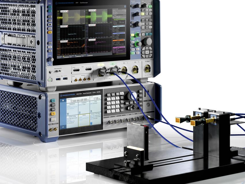
Rohde & Schwarz Analyzing automotive radar signals with an oscilloscope 5TEST SETUP
External mixers are used to downconvert the radar signals to the oscilloscope’s frequency range (Fig. 1). The R&S®FS-Z90 harmonic mixers in this
example use the sixth harmonic of a local oscillator (LO) to generate the desired output frequency. An R&S®SMA100B HF and microwave signal
generator serves as the LO, while the evaluation board of a commercial radar sensor acts as the radar signal source.
Automotive radar Radar signal analysis
(77 GHz to 81 GHz) IF, e.g. 3 GHz CH 1
RX 1 HF
♦ ♦
1 2 ♦ ♦
3 4
RX 2 HF
e.g. USB connection IF, e.g. 3 GHz CH 2
♦ ♦
3 3 ¸RTP064/¸RTP 084
oscilloscope
Power splitter
¸ZV-Z1227
PC with
♦ 3 ♦ 1 FH-SG-90 E band horn antenna
♦
control software
2 R&S®FS-Z90 harmonic mixer
♦ 3 R&S®RT-ZA17 high-precision,
low-loss matched cable pair
♦
¸SMA100B
signal generator 4 R&S®RT-ZA16 precision BNC to
SMA adapter (16 GHz)
Fig. 1: Test setup for multichannel radar analysis with an oscilloscope. The radar signal is downconverted to an IF frequency of 3 GHz by the harmonic mixers and fed to the oscilloscope.
The power splitter and one mixer are not needed for a test setup with only one channel.
6MEASUREMENT TASK
CONFIGURATION OF THE RADAR DEEMBEDDING FUNCTION SIMPLI-
SENSOR FIES SIGNAL ANALYSIS
The radar system uses a chirp sequence signal consisting of several high frequen- The IF signals from the mixers are fed to the oscilloscope inputs. The attenua-
cy pulses in direct succession. Each of these pulses is a chirp with a bandwidth tion and S-parameters of the individual components in the signal path can be
of approximately 4 GHz. The sensor is configured so that the frequency of the ra- taken into account by the hardware and software deembedding functions of the
dar signal rises linearly from 77 GHz to nearly 81 GHz (up chirp). The end of the R&S®RTP. The impact of deembedding is illustrated in Fig. 2. The mixer attenu-
sequence is followed by a break of several milliseconds (interframe time). During ates the received signal over the entire frequency range. The received signal
this time, the radar processor calculates the locations and speeds of the detected is detected with decreasing amplitude as the frequency increases (Fig. 2, left).
objects. Deembedding compensates for these losses (Fig. 2, right), enabling the oscillo-
scope to analyze the actual signal.
Fig. 2: An FMCW signal with deembedding disabled (left screenshot) and enabled (right screenshot). The frequency response correction reconstructs the signal in its original frequency range.
Rohde & Schwarz Analyzing automotive radar signals with an oscilloscope 7MEASUREMENT OPTIONS
SINGLE-CHANNEL ANALYSIS
Isolation of individual radar pulses with the width trigger Checking the modulation in the radar signal Other measurement functions help users quickly de-
Stable trigger conditions are essential for reliable sig- For the best possible spatial resolution, current au- termine important parameters such as the rise time
nal analysis with an oscilloscope. Oscilloscopes usu- tomotive radars use bandwidths up to 4 GHz. The of the linear frequency modulation. For example, the
ally offer advanced trigger options in addition to tra- R&S®RTP meets the associated T&M requirements. oscilloscope’s FFT function creates a spectrogram
ditional edge triggering. However, these options can With its high sampling rate and large memory, it cap- that shows how the radar signal changes over time.
only be used up to a certain bandwidth, depending tures the downconverted radar signal with a suffi- These two analysis methods (Figs. 2 and 3) allow us-
on the manufacturer. Thanks to its digital triggering, ciently high sampling frequency. The analysis tools ers to perform an initial check of the bandwidth and
the R&S®RTP can use the entire range of trigger op- included in the base configuration are sufficient to the modulation.
tions up to the maximum bandwidth. check the modulation in the radar signal. The down-
converted signal that is used starts at 1 GHz and rises Investigating an FMCW radar signal with the R&S®VSE
Simple edge triggering is not useful for these mea- linearly to 5 GHz. An initial check of these frequen- software's transient analysis function
surement tasks since the oscilloscope will trigger cies starts with a frequency measurement that is con- The R&S®VSE vector signal explorer software offers
on virtually any point of the signal due to the nature figured to perform many frequency measurements advanced analysis tools for investigating radar sig-
of the radar pulse. A pulse width trigger, which can within one acquisition (frequency tracking). The result nals, for example to check the linearity of a frequency
be used to trigger on the interframe time between is a display of the downconverted frequency versus modulated continuous wave (FMCW) radar signal,
pulses, is more useful because it allows individual time fIF(t). which has a large influence on the Doppler properties
pulses or entire pulse sequences to be detected and of a target. The software’s R&S®VSE-K60C transient
analyzed. The trigger condition can be configured for At higher frequencies, the data points are closer to- chirp measurements option performs this measure-
specific radar signal parameters, for example to only gether, making the measurement more difficult. ment with high accuracy (Fig. 4). The R&S®VSE-K60C
display pulses with a specific duration. Noise often increases, but can be filtered out by the displays the frequency response fIF(t) and calculates
oscilloscope’s lowpass filter math function. It is pos- the deviation from the ideal linear phase. The soft-
See also the "Trigger on radar RF pulses with an oscil- sible to change the scaling of fIF(t) (increase the fre- ware can be installed directly on the oscilloscope or
loscope" application card: quency axis) to display the radar signal in its original on an external computer. The data is transferred from
https://scdn.rohde-schwarz.com/ur/pws/dl_down- frequency range fHF(t) (Fig. 3). the oscilloscope to the computer via Ethernet, for
loads/dl_application/pdfs/Trigger-on-radar-RF-pulses_ example.
ac_en_3609-2000-92_v0100.pdf
8Fig. 3: Top: With suitable scaling and filtering, the radar signal can be displayed
in its original frequency range fHF(t). Measurement functions provide important
parameters, such as the slew rate of the chirp. Bottom: The FFT shows the power
profile of the chirp.
Fig. 4: Transient analysis of a chirp sequence signal with the R&S®VSE-K60C transient
chirp measurements option. The pulse power versus time is shown at the top left. The
linear frequency response can be seen in the top middle and in the spectrogram on the
bottom left. The software lists the properties of the detected pulses in a table (bottom
middle). The properties can also be investigated in detail in graphical form. The chirp
rate and frequency deviation are shown on the right.
Rohde & Schwarz Analyzing automotive radar signals with an oscilloscope 9MEASURING PHASE AND AMPLITUDE DIFFERENCES
WITH MULTICHANNEL ANALYSIS
Many automotive radars are equipped with multiple transmit and receive anten-
na arrays. These determine the directivity of the antenna and allow beamforming Using FFT to determine phase properties
and detection of the direction of the target. To specifically investigate the transmit For the phase measurement, the analysis range is limited to a narrow time
properties, for example, multiple mixers can be operated simultaneously on the corridor, and the phase difference of the two input channels is calculated
oscilloscope. The setup is similar to that for single-channel analysis; the LO signal from the phase properties determined by FFT (Fig. 5).
simply has to be distributed to all the mixers (Fig. 1).
The advantage of the indirect method using FFT is the larger time analysis
Oscilloscope as phase coherent receiver range. Whereas a single measurement of the phase difference in the time do-
When used as a phase coherent receiver, the oscilloscope analyzes multiple sig- main can be strongly dominated by noise, in the frequency domain multiple
nals relative to each other. Typically, the phase differences and difference between signal periods are compared with each other, resulting in a significantly small-
er measurement uncertainty.
the two spectra are analyzed. The FFT function of the R&S®RTP is also helpful. It
is used to calculate the amplitude spectra of the signals in the two channels. The
difference is then calculated with another math function and displayed.
Fig. 5: Multichannel measurement of a chirp sequence.
The pulses are shown in the time domain (top), the
spectra of the individual channels in the middle, and
the amplitudes and phase difference are shown on the
bottom left and bottom right, respectively.
10DEBUGGING BY CORRELATING RADAR
SIGNALS WITH OTHER SIGNALS
Simultaneous acquisition of CAN bus or automotive Ethernet signals together with
radar signals
The R&S®RTP oscilloscope can measure the amplitude and phase differences of
multiple antenna paths simultaneously and correlate the radar signals with other
signals, such as the supply voltage or digital bus signals (Fig. 6). Simultaneously
acquiring CAN bus or automotive Ethernet signals together with radar signals is
particularly helpful during development and debugging. The analysis time of the
radar sensor can be determined from the delay between the radar signal and the
bus protocol signal. If the measured delay exceeds a specified time, deployment
in autonomous vehicles is not acceptable.
Fig. 6: Measurement of the delay between the radar
signal (left) and the CAN protocol frame (right). The
oscilloscope triggers on the radar signal and, using
the “Trigger to Frame“ function, measures a delay of
9.54 ms from when the radar signal is transmitted to
when the protocol transfer starts (bottom left).
Rohde & Schwarz Analyzing automotive radar signals with an oscilloscope 11PORTFOLIO
Type Designation Application
R&S®RTP064/R&S®RTP084 Oscilloscope Radar signal analysis on up to four channels
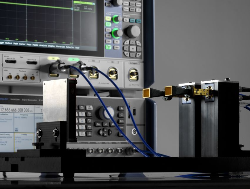
¸SMA100B Signal generator Local oscillator source
¸ZV-Z1227 Power splitter Feeds the LO signal to the two harmonic mixers
2 × FH-SG-90 E band horn antenna The horn antenna receives the radar signal
The harmonic mixers downconvert the radar signal
2 × R&S®FS-Z90 Harmonic mixers
is to an IF frequency of 3 GHz
High-precision, low-loss matched cable pair, Matched HF cable pair with 3.5 mm plugs on both
R&S®RT-ZA17
length: 1 m ends
Adapts SMA connector to BNC connector on the
R&S®RT-ZA16 Precision BNC to SMA adapter
R&S®RTP
The software’s R&S®VSE-K60C transient chirp
R&S®VSE Vector signal explorer software measurements option analyzes transients with
high accuracy
12AUTOMOTIVE TEST SOLUTIONS
As a leading global manufacturer of test and measurement equip-
ment, Rohde & Schwarz offers expert know-how for all phases of Analysis of radar signals is described in
automotive development – from predevelopment to R&D to pro- detail in the application note “Automotive
duction. OEMs, Tier 1s and chip suppliers benefit from the com- Radar – Chirp Analysis with R&S®RTP
pany’s reliable solutions for high frequency, high bandwidth and Oscilloscope”.
high-speed test challenges. Rohde & Schwarz is the market lead-
er for testing radar sensors, automotive Ethernet conformance,
connectivity (5G, V2X, eCall, GNSS), infotainment, EMI precompli-
ance and EMC. The company also offers outstanding solutions for
in-circuit and functional testing (ICT/FCT) during ECU production.
All of these test solutions will ensure maximum efficiency in com-
pliance with the highest quality standards, assuring that various
automotive components function correctly, coexist successfully https://www.rohde-schwarz.com/
and communicate with the outside world without errors. applications/automotive-radar-chirp-
analysis-with-r-s-rtp-oscilloscope-ap-
plication-note_56280-667909.html
https://www.rohde-schwarz.com/video/77-ghz-automotive-radar-part-3-video-
detailpage_251220-666562.html
Rohde & Schwarz Analyzing automotive radar signals with an oscilloscope 1314
Rohde & Schwarz Analyzing automotive radar signals with an oscilloscope 15
About Rohde & Schwarz
The Rohde & Schwarz electronics group offers innovative
solutions in the following business fields: test and mea-
surement, broadcast and media, secure communications,
cybersecurity, monitoring and network testing. Founded
more than 80 years ago, the independent company which
is headquartered in Munich, Germany, has an extensive
sales and service network with locations in more than
70 countries.

www.rohde-schwarz.com

Rohde & Schwarz customer support
www.rohde-schwarz.com/support

                                                                                                         3609966392
                                                                   3609.9663.92 01.00 PDP 1 en
R&S® is a registered trademark of Rohde & Schwarz GmbH & Co. KG

                                                                                                 3609.9663.92 01.00 PDP 1 en
PD 3609.9663.92 | Version 01.00 | April 2020 (jr)
Trade names are trademarks of the owners
Analyzing automotive radar signals with an oscilloscope
Data without tolerance limits is not binding | Subject to change
© 2020 Rohde & Schwarz GmbH & Co. KG | 81671 Munich, Germany
You can also read