Smart Thermostat RDS110 - Siemens
←
→
Page content transcription
If your browser does not render page correctly, please read the page content below
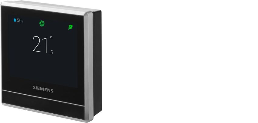
Smart Thermostat
RDS110

                     To control heating applications in apartments, single family homes, dormitories,
                     and other residential as well as commercial spaces.
                     ●   Backlit, auto-dimming 90 mm color LCD touch screen for intuitive local operation
                     ●   Mobile app for smartphones
                     ●   Patented1) self-learning algorithm with PID response
                     ●   Green leaf button for energy-optimized operation
                     ●   Air quality indication via built-in sensor
                     ●   Operate automatically following a scheduler
                     ●   Multifunctional inputs for operating mode switchover contacts, remote sensors,
                         etc.
                     ● Two relay outputs for heating equipment, humidifier, dehumidifier or domestic hot
                         water boiler
                     ● Satisfy EU.BAC certification level AA for Home Control and Class IV according to
                         the Eco design directive
                     1) Patent pending

A6V10807602_en--_h                                                                               Siemens AG
2021-07-16                                                                                Smart Infrastructure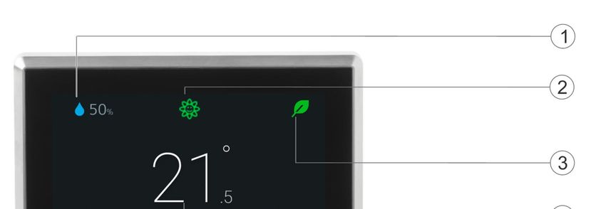
Room thermostat features
                ● Direct temperature and operating mode selection
                ● RoomOptiControl function with Green leaf *) button for energy-optimized operation
                ● Air quality indication: “Good”, “Okay”, “Poor”
                ● Temperature setting limitation for use in public spaces
                ● Screen lock protection against unauthorized access
                ● Manual switchover between “At home”, “Away” and “Off” on touch screen
                ● Room temperature control using the built-in temperature sensor or an optional remote
                   sensor
                ● Optional temperature averaging using an additional remote temperature sensor
                ● Patented self-learning algorithm with PID response (patent pending) guaranteeing opti-
                   mum temperature control performance in all room types
                ● Optimum start control function that advances the switch-on time to ensure the selected
                   setpoint is reached as required
                ● Floor temperature limitation using a remote sensor in electric floor-heating applications
                ● Humidity control using the built-in humidity sensor or an optional remote sensor
                ● Presence detection using a built-in PIR sensor or approach sensor
                ● Two multifunctional inputs, optional and configurable for:
                            – Universal contact
                            – Operating mode switchover contact
                            – Remote room temperature sensor
                            – Floor temperature sensor
                            – Outside air temperature sensor
                            – Remote humidity sensor
                       ●   Two relay outputs for:
                            – Heating equipment (see “Use” for examples)
                            – Extra output for domestic hot water (DHW) boiler, humidifier or dehumidifier
                       ●   Periodic pump/valve operation to protect against seizing
                       ●   Navigation wizard for guided, fast commissioning
                       ●   Remote firmware upgrade capability

                       *) The Green leaf indication informs the user that the system provides energy-optimized op-
                       eration. When the leaf is red, the thermostat setting has been changed. Touch the red leaf to
                       return the setting to energy-optimized operation. See the user guide for more information on
                       this function.

Remote operation and monitoring
                ● Mobile app for smartphones based on iOS and Android operating systems
                ● Support “Dark” and “Light” background colors on mobile app
                ● Manual switchover between “At home”, “Away” and “Off” operating modes on mobile app
                ● Individual scheduler for each day of the week can be programmed via mobile app with
                   the following operating modes (max. 5 modes per day)
                            – “Comfort”: To enjoy comfort and coziness when you are at home.
                            – “Economy”: To save energy when maximum comfort is not required, e.g. in the even-
                              ing or at night.
                             – “Unoccupied”: To save energy costs by reducing the temperature setpoint, e.g. when
                               the room is unoccupied.
                       ●   Individual scheduler for domestic hot water boiler
                       ●   User account management

2
Siemens                                                                                           A6V10807602_en--_h
Smart Infrastructure                                                                                         2021-07-16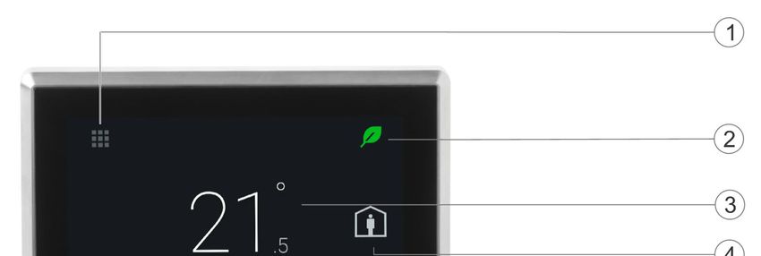
●   Monitoring of temperature and humidity
                       ●   Monitoring of indoor air quality: “Good”, “Okay”, “Poor”
                       ●   Secure access and data transmission with the Siemens Cloud Computing Platform

Use
                       The RDS110 is designed to control heating applications in apartments, single family homes,
                       dormitories, and other residential as well as commercial spaces.

                       RDS110 controls the following plant components:
                       ● Gas boiler
                       ● Radiator with valve
                       ● Radiator with pump
                       ● Electric floor heating
                       ● Fan with electric heating
                       ● Floor heating with valve
                       ● Floor heating with pump
                       ● Electric radiator
                       ● Electric boiler
                       ● Generic heating device

                             NOTICE

                       When selecting the gas boiler application, ensure a hydronic heating is used. The
                       RDS110.R is not calibrated for use in combination with a gas-fired ducted heating system.

                       In addition, an external relay is available to optionally control a domestic hot water (DHW)
                       boiler, humidifier or dehumidifier.
                       Two multifunctional inputs, optional and configurable for:
                       ● Operating mode switchover contact
                            – The operating mode can change according to contact status.
                       ●   Remote room temperature sensor
                            – The remote temperature sensor can acquire the current room temperature. If the
                               sensor input signal is lost, the thermostat controls the room according to the internal
                               sensor.
                       ●   Floor temperature sensor
                            – The floor heating limitation function prevents the floor temperature from exceeding a
                              preset value.
                       ●   Outside air temperature sensor
                            – The outside air temperature sensor can acquire outside air temperature information
                              for display on touch screen.
                       ●   Remote humidity sensor
                            – The thermostat can control a standalone humidifier or dehumidifier. The relative
                              humidity is measured by the remote humidity sensor or internal humidity sensor.

Mechanical design
                The room thermostat consists of the following parts:
                ● Housing front with touch screen and sensors
                ● Housing rear with terminals and relays
                ● Metallic mounting plate for wall mounting
                ● Accessories

                                                                                                                         3
Siemens                                                                                              A6V10807602_en--_h
Smart Infrastructure                                                                                         2021-07-16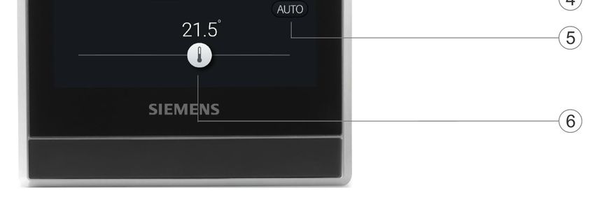
Operation and settings

                       Normal display

                       1   Tap to display detailed information and additional setting possibilities.
                       2   Shows if the system is in an energy-optimized mode. If the leaf is red, predefined
                           settings were changed. Tap the red leaf to restore energy-saving mode. The leaf again
                           turns green.
                       3   Room temperature*)
                       4   Tap to toggle between “At home” and “Away”.
                       5   Shows if the thermostat works automatically (    ) or manually (    ). Using a
                           scheduler can mean the following:
                           ● If there is Cloud connection and the scheduler has already been set, the thermo-
                              stat follows the scheduler. A temporary change of the temperature setpoint only
                              takes effect during the currently scheduled mode.
                           ● If there is Cloud connection, but no scheduler has been set, the thermostat follows
                              the default scheduler set by the system.
                           ● If there is no Cloud connection, the thermostat cannot retrieve scheduler infor-
                              mation.

                       6   Temperature setpoint slider. Icon color changes as setpoint is changed.
                           ● If you increase the setpoint by dragging the slider to the right to warm up the room,
                              the slider color changes to orange.
                           ● If no heating occurs, the slider color changes to white.

                            NOTICE

                       After initial setup of the thermostat, the displayed room temperature may not be correct be-
                       cause the temperature sensors need time for calibration. Wait for at least one hour for the
                       calibration.

4
Siemens                                                                                                A6V10807602_en--_h
Smart Infrastructure                                                                                           2021-07-16
Idle display

                       1    Room relative humidity
                       2    Shows room air quality:
                            ● If the icon is green, air quality is good.
                            ● If the icon is orange, air quality is okay.
                            ● If the icon is red, air quality is poor.

                       3    Shows if the system is in an energy-optimized mode. If the leaf is red, predefined
                            settings were changed. Tap the red leaf to restore energy-saving mode. The leaf again
                            turns green.
                       4    Room temperature
                       Note: Depending on how the thermostat is set up, the displayed options in idle mode may
                       differ.

Type summary

                       Product number                  Stock number                 Description

                       RDS110                          S55772-T100                  Room thermostat

Ordering
                       ●   When ordering, indicate product number, stock number and description.
                       ●   Order valve actuators separately.

                                                                                                                    5
Siemens                                                                                           A6V10807602_en--_h
Smart Infrastructure                                                                                      2021-07-16
Inbox items

                       Items                                      Quantity

                       Thermostat (front and rear)                1

                       Metallic mounting plate                    1

                       Set of screws and plastic insert           1

                       Quick guide                                1

                       Mounting instructions                      1

                       Activation code sticker                    1

                       Wiring sticker                             1

Equipment combinations

                       Remote sensors

                       Type of unit        Product no.    LG-     Pt1000   NTC 10k DC 0…10 V Datasheet*
                                                          Ni1000 at 0 °C   at 25 °C
                                                          at 0 °C

                       Room temperature sensors

                       - Wall-mounted      QAA24          x                                   1721

                                           QAA2012               x                            1745

                                           QAA2030                         x                  1745

                                           QAA2061                                 x          1749

                                           QAA2061D2)                              x          1749

                       - Flush-mounted1)   AQR2531AN      x                                   1408
                                           W

                                           AQR2532NN                               x          1411
                                           W

                       - Concealed         QAA64          x                                   1722
                                           (vandal-proof)

                       Outdoor temperature sensors

                                           QAC22          x                                   1811

                                           QAC2012               x                            1811

                                           QAC2030                         x                  1811

                                           QAC3161                                 x          1814

                       Cable temperature sensors

                                           QAP21.3        x                                   1832

                                           QAP22          x                                   1831

6
Siemens                                                                                   A6V10807602_en--_h
Smart Infrastructure                                                                              2021-07-16
Type of unit Product no. LG- Pt1000 NTC 10k DC 0…10 V Datasheet*
Ni1000 at 0 °C at 25 °C
at 0 °C
QAP21.3/800 x 1832
0
QAP2012.150 x 1831
QAP1030.200 x 1831
Room humidity sensors
- Wall-mounted QFA2000 x 1857
- Wall-mounted QFA2020 x (T) x (r.h.) 1857
including
temperature QFA2060 x (T+r.h.) 1857
QFA2060D2) x (T+r.h.) 1857
- Flush-mounted1) AQR2534AN x (T) x (r.h.) 1410
including W
temperature + AQR2540Nx
AQR2535NN x (T+r.h.) 1410
W
+ AQR2540Nx
* The documents can be downloaded from http://siemens.com/bt/download by specifying the
product number as shown in the above table.
1) Requires a mounting plate and/or design frames.
2) With digital display.
Actuators
Type of unit Product no. Datasheet*
Electromotoric actuator SFA21/18 4863
SUA21/3 A6V10446174
Electrothermal actuator (for STA23.. 4884
radiator valves) AC 230 V, NC
Electrothermal actuator (for STA73.. 4884
radiator valves) AC 24 V, NC
Electrothermal actuator STP23.. 4884
AC 230 V (for small valves
2.5 mm), NO
Electrothermal actuator STP73.. 4884
AC 24 V (for small valves
2.5 mm), NO
7
Siemens A6V10807602_en--_h
Smart Infrastructure 2021-07-16Accessory
Type of unit Product no. Datasheet*
White decoration frame and metallic ARG100.01 A6V11190640
mounting plate for installation on S55772-T102
rectangular conduit box (1 set)
* The documents can be downloaded from http://siemens.com/bt/download by specifying the
product number as shown in the above table.
Product documentation
Topic Title Document ID
Mounting and installation Mounting instruction A5W90001424
Installation and operation User guide A6V10877569
Startup wizard Quick guide A5W90001422
CE declaration A5W90002476
Product environmental declaration A5W90003412
Related documents such as environmental declarations, CE declarations, etc., can be down-
loaded at: http://siemens.com/bt/download.
Notes
Security
CAUTION
National safety regulations
Failure to comply with national safety regulations may result in personal injury and property
damage
● Observe any national provisions and comply with the appropriate safety regulations.
Engineering
See the product documentation for information on engineering, selection and sizing connect-
ing cables for supply voltage and field devices.
Installation
The mounting plate of the thermostat can be installed on CEE/VDE conduit boxes and on
square boxes 75 x 75 mm. For installation on a rectangular conduit box (e.g. 105 x 72 mm),
accessory ARG100.01 must be ordered, which includes 1 set of white decoration frame and
bigger mounting plate.
WARNING
No internal line protection for supply lines to external consumers
Risk of fire and injury due to short-circuits
● Adapt the line diameters as per local regulations to the rated value of the installed over-
8
Siemens A6V10807602_en--_h
Smart Infrastructure 2021-07-16current protection device.
● The AC 230 V mains supply line must have an external circuit breaker with a rated cur-
rent of no more than 10 A.
● Properly size the cables to the thermostat and for the outputs for AC 230 V mains volt-
age.
● Use only AC 230 V isolated wired cables, as the conduit box carries AC 230 V mains
voltage.
● Remove wired bridge L - Q11 when loads work with voltages other than AC 230 V.
● Inputs X1-M-X2: Several switches may be connected in parallel. Consider overall max-
imum contact sensing current for switch rating.
● Disconnect from power supply before removing the front of the thermostat.
Commissioning
Refer to the Quick guide and User guide (see Product Documentation) to configure your de-
vice. Commissioning includes the following:
● Internet connection
● Application setup
● Account registration and device pairing
Note:
Before configuring your thermostat, make sure you are connected to the Internet, have a
valid email address, and a smartphone.
Mounting
● The devices are suitable for wall mounting.
● Recommended height: 1.50 m above the floor.
● Do not mount the devices in recesses, shelves, behind curtains or doors, or above or
near heat sources.
● Avoid direct solar radiation.
● Seal the conduit box or the installation tube if any, as air currents can affect sensor read-
ings.
● Adhere to allowed ambient conditions.
Operation
End users can operate the thermostat directly on the touch screen, or download the mobile
app “Siemens Smart Thermostat RDS” and perform operations on their smartphones,
including:
● Creating and managing accounts
● Setting the operating mode (Auto, away, home, manual)
9
Siemens A6V10807602_en--_h
Smart Infrastructure 2021-07-16● Changing the room temperature (by setting new setpoints)
● Setting a weekly scheduler (heating and domestic hot water)
● Green leaf (switching to energy-optimized operation)
Supported smartphone types are as follows:
Operating system
OS OS version App store
iOS iOS 12 or above App store®
Android AndroidTM 10.0 or above Google PlayTM
Maintenance
The thermostat is designed for maintenance-free operation.
Disposal
The device is considered an electronic device for disposal in accordance
with the European Guidelines and may not be disposed of as domestic
garbage.
● Dispose of the device through channels provided for this purpose.
● Comply with all local and currently applicable laws and regulations.
Warranty
Technical data on specific applications are valid only together with Siemens products listed
under "Equipment combinations". Siemens rejects any and all warranties in the event that
third-party products are used.
Radio equipment directive
The equipment is using harmonized frequency in Europe and complies with the Radio
Equipment Directive (2014/53/EU, formerly 1999/5/EC).
10
Siemens A6V10807602_en--_h
Smart Infrastructure 2021-07-16Technical data
Power supply
Power supply
Operating voltage AC 230 V (+10% / -15%)
Frequency 48…63 Hz
Power consumption Max. 9 VA
Standby power consumption (LCD off) 0.6 W
Max. external supply line fusing 10 A circuit breaker
Radio parameters
Radio parameters
Frequency band 2.4…2.4835 GHz
Maximum radio-frequency power 18 dBm
WLAN standard IEEE 802.11b/g/n (HT20)
WLAN channel 1~13
11
Siemens A6V10807602_en--_h
Smart Infrastructure 2021-07-16Inputs
Connections to multifunctional inputs X1 - M - X2
Passive temperature sensors
- Cable length max. (copper cable section) 90 m (1.5 mm2 wire), 70 m (1 mm2 wire)
60 m (0.75 mm2 wire), 40 m (0.5 mm2 wire)
- NTC type NTC10K at 25 °C
Room temperature range 0…50 °C
Outdoor temperature range -50…80 °C
- Ni type Ni1000 at 0 °C
Room temperature range 0…50 °C
Outdoor temperature range -50…80 °C
- Pt type Pt1000_375/Pt1000_385 at 0 °C
Room temperature range 0…50 °C
Outdoor temperature range -50…80 °C
Active DC 0 V ...10 V sensors Min./max. configurable via parameters
- Room temperature range (default) 0…50 °C
- Outdoor temperature range (default) -50…80 °C
- Humidity range (default) 0…100%
Digital contacts
- Operating action Selectable NO/NC
- Contact sensing DC 14…40 V, 8 mA (typ.)
- Parallel connection Max. 20 thermostats per switch
- Input function Selectable
Outputs
Switching capacity of relay
Voltage Q11, Q12, Q14 Potential free, AC 24…230 V
Current, min max resistive (inductive) 5 mA...5(2) A
Voltage Q21, Q22, Q24 Potential free, AC 24…230 V
Current, min max resistive (inductive) 5 mA...5(2) A
Note: Connecting different voltages on Q1x and Q2x is allowed (double insulation).
NOTICE
Remove wired bridge L-Q11 when loads work with voltages other than AC 230 V.
12
Siemens A6V10807602_en--_h
Smart Infrastructure 2021-07-16Operational data
Setpoint setting range
0…50 ℃
12…35 ℃ (default)
Built-in room temperature sensor
Temperature range Accuracy at 25 ℃ Display resolution
0…50 ℃ ±0.5 K 0.5 K
Built-in room humidity sensor
Humidity range Accuracy at 25 ℃ Display resolution
0%...100% ±5% r.h. 1%
Connections
Interfaces
Micro USB A service port is limited to firmware upgrades
and onsite diagnosis by professionals.
Wiring connections
Screw terminals Solid wires or prepared stranded wires:
Max. 1 × 0.5... 2.5 mm2 (14…20 AWG)
Conformity
Ambient conditions and protection classification
Safety class as per EN60730 Class II
Degree of protection of housing as per EN IP30
60529
Classification as per EN 60730
Function of automatic control devices Type 1
Degree of contamination 2
Overvoltage category III
Climatic ambient conditions
13
Siemens A6V10807602_en--_h
Smart Infrastructure 2021-07-16Ambient conditions and protection classification
Storage as per EN 60721-3-1 Class 1K3
Temperature -25...65 °C (-13... 149 °F)
Humidity 5...95%
Transport (packaged for transport) as per EN Class 2K3
60721-3-2 Temperature -25...65 °C (-13... 149 °F)
Humidity 5...95%
Operation as per EN 60721-3-3 Class 3K5
Temperature -5...50 °C (23... 122 °F)
Humidity 5...95%
Mechanical ambient conditions
Storage as per EN 60721-3-1 Class 1M2
Transport as per EN 60721-3-2 Class 2M2
Operation as per EN 60721-3-3 Class 3M2
Standards, directives and approvals
EU conformity (CE) A5W90002476*)
RCM conformity A5W90002477*)
China CMIIT ID 2017DJ1647, A5W90002478*)
EAC conformity Eurasian Conformity*)
Environmental compatibility The product environmental declaration
A5W90003412*) contains data on
environmentally compatible product design
and assessments (RoHS compliance,
materials composition, packaging,
environmental benefit, disposal).
*) The documents can be downloaded from http://siemens.com/bt/download.
eu.bac certification
Type License Application Energy Efficiency Label Control accuracy (K)
RDS110 217739 Water heating AA 0.5
systems (radiator)
See product list at: http://www.eubaccert.eu/licences-by-criteria.asp
14
Siemens A6V10807602_en--_h
Smart Infrastructure 2021-07-16Eco design and labeling directives
Based on EU Regulation 813/2013 (Eco design directive) and 811/2013
(Labelling directive) concerning space heaters, combination heaters, the
following classes apply:
Application with On/Off operation of a heater Class I Value 1%
PWM (TPI) room thermostat, for use with Class IV Value 2%
On/Off output heaters
General data
General
Dimension Refer to Dimensions on page 18
Weight Thermostat with package, user document and 435 g
accessory
Thermostat 231 g
Color Silver plating
Housing: Pantone black
Diagrams
Connection terminals
Terminal Use
L Mains connection, live conductor
N Mains connection, neutral conductor
Q11 Control input (com)
Q12 Control output; NC contact
Q14 Control output; NO contact
Q21 Control input (com)
Q22 Control output; NC contact
Q24 Control output; NO contact
X1, X2, M Multifunctional inputs
15
Siemens A6V10807602_en--_h
Smart Infrastructure 2021-07-16Wiring diagrams
● The thermostat is delivered with one wired bridge ① (L-Q11) for easy installation of
AC 230 V HVAC equipment (example 1).
● When loads use voltages other than AC 230 V, bridge ① must be removed before wiring
the loads to the thermostat (example 2).
● If the load current through Y2 is more than 3 A, bridge between L-Q11 cannot be used.
Adapt parameter “Q22/Q24 electrical load” in “Advanced Settings” / “Optimization”.
● For application with higher currents (Y1 > 3 A or Y2 > 2 A), adapting parameter
“Q22/Q24 electrical load” in “Advanced Settings” / “Optimization” accordingly is recom-
mended.
Basic
① AC 230 V
Advanced
Example 1: Loads = Example 2: Loads Y1, Y2 ≠
AC 230 V AC 230 V
① AC 230 V on Y1, Y2
Y1 HVAC equipment B1, B2 External sensors
Y2 DHW / Dehumidifier / Humidifier S1, S2 External switches
WARNING
The total current rating must not exceed 8 A.
16
Siemens A6V10807602_en--_h
Smart Infrastructure 2021-07-16Application examples
Applications
Gas boiler Electric boiler
Radiator with valve Floor heating with valve
17
Siemens A6V10807602_en--_h
Smart Infrastructure 2021-07-16Applications
Radiator with pump Floor heating with pump
Electric radiator Electric floor heating
Fan with electric heating Key
N1 RDS110
B1 Floor temperature sensor
Y1 Valve
M1 Circulating pump
K1 Heat generator (e.g. boiler)
18
Siemens A6V10807602_en--_h
Smart Infrastructure 2021-07-16Dimensions
RDS110
Front and rear modules Metallic mounting plate
ARG100.01
White decoration frame Metallic mounting plate
Revision history
Edition Date Software version Changes Section Pages
7 July 2021 32.2.48 or higher Removed information about window Cover page 1
contact. Room thermostat 2
features 3
Use 8
Installation
6 Jan 2019 32.2.27 or higher Changed setpoint setting range from Technical data 12
“12…35 ℃” to “0…50 ℃, 12…35 ℃
(default)”.
5 July 2018 32.2.27 or higher - - -
19
Siemens A6V10807602_en--_h
Smart Infrastructure 2021-07-16Edition Date Software version Changes Section Pages
4 May 2018 32.2.18 or higher ● Added EAC logo Cover page 1
● Added EAC conformity Technical data 13
● Updated application names Application 17
examples
3 April 2018 32.2.18 or higher ● Added standby power consump- Technical data 11
tion figure.
2 January 32.2.18 or higher ● Changed operating modes from Remote operation 2
2018 Comfort, Pre-comfort and Econ- and monitoring
omy to Comfort, Economy and
Unoccupied.
● Added “Dark” and “Light” back-
ground color support for mobile
app.
1 August 2017 32.2.10 New document --- ---
20
Siemens A6V10807602_en--_h
Smart Infrastructure 2021-07-16Issued by
© Siemens Switzerland Ltd, 2021
Siemens Switzerland Ltd
Technical specifications and availability subject to change without notice.
Smart Infrastructure
Global Headquarters
Theilerstrasse 1a
CH-6300 Zug
+41 58 724 2424
www.siemens.com/buildingtechnologies
Document ID A6V10807602_en--_h
Edition 2021-07-16You can also read