Series 2 0.0 Single - Owners Manual - Argon ...
←
→
Page content transcription
If your browser does not render page correctly, please read the page content below
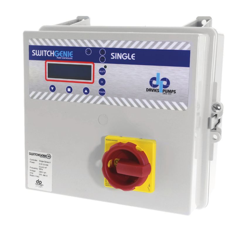
PUMP CONTROLLER

Series 2
                                                              0.0
                        Intelligent                        Instantaneous
                        Controller    Run dry protection   digital readout

  Year
 Warranty

    MADE IN ITALY   Single - Owners Manual
PUMP CONTROLLER
SWITCH
Single
Introduction
PRESENTATION 3
DESCRIPTION 3
HANDLING 3
General use and safety
WARNINGS 4
CAUTION 4
KEYPAD AND LIGHTS INDICATIONS 5
ALARMS 6
TYPICAL INSTALLATIONS 8
Installation
ASSEMBLING 10
OPERATION MENU 11
ELECTRICAL CONNECTIONS 12
ADJUSTMENTS AND SETTINGS 14
(BASIC)
ADJUSTMENTS AND SETTINGS 16
(ADVANCED)
TRIMMER SETTINGS 33
CONTACT ALARM OUTPUTS 33
Maintenance
PUMPS STOP 34
SERVICE 34
SPARE PARTS 34
WASTE DISPOSAL 34
NOTES 35
WARRANTY 36
Certifications
CERTIFICATE OF CONFORMITY 39
2 SWITCHGENIE | argondistributors.co.nzIntroduction SWITCH
Single
PRESENTATION
The purpose of this manual is to provide the Our units must be installed in sheltered, well-
necessary information for the proper installation, ventilated, non-hazardous environments and
use and maintenance of SwitchGenie Single. must be used at a maximum temperature of
The user should read this manual before operating +40°C and minimum of -5°C.
the unit. Improper use may cause damage to
the machine and lead to the forfeiture of the
warranty coverage. Always specify the model
identification code when requesting technical
information.
DESCRIPTION
These control panels are designed for controlling • Panel alarm LED
1 motor or electric pump used in pressurization • 12V DC output for buzzer
systems or in applications for emptying wells or • Alarm output relay 12VDC or NO
water tanks.. contact
Argon Distributors shall not be liable for any • Alarm output relay 230V or 400V
damage caused or suffered by the unit as a • Min/max voltage, current, frequency
result of its unauthorised or improper use. • Phase failure
• Min COS FI
TECHNICAL FEATURES • Motor Klixon
• Water in oil chamber
Self learning of the motor data; min-max
amperage protection (A); dry running protection
using cos and min current; min and max
voltage protection (V); phase failure protection;
start and stop delay; delay network restore,
protection delay, frequency 50-60Hz.
HANDLING STORING
The control panel must be handled with If for any reason the unit is not installed
care, as falls and knocks can cause damage after it has reached its destination it must be
without any visible external signs. stored properly.
The external packaging and the separately
PRELIMINARY INSPECTION packed accessories must remain intact, and
After you have removed the external packaging, must be protected from the weather,
visually inspect the control panel to make sure it especially from freezing temperatures,
has suffered no damage during shipping. and from any knocks or falls.
If any damage is visible, inform your supplier
as soon as possible, no later then five days from
the delivery date.
SWITCHGENIE | argondistributors.co.nz 3Safety information PUMP CONTROLLER
SWITCH
Single
WARNINGS
RISK OF ELECTRIC SHOCK
Failure to follow the instructions in this manual, carries a risk of electric shock.
RISK FOR PEOPLE AND PROPERTY
Failure to follow the prescriptions in this manual, carries a risk of damage to
persons and/or property.
WARNING
Failure to observe the prescriptions in this manual, cause damage to the pump,
the unit or the system.
CAUTION
ATTENTION: PUMPS
• Make sure the pumps are fully primed before you start it.
• Make sure the pumps are running with the correct rotation.
• The electric pumps or the motors can start up automatically.
ATTENTION: ELECTRICAL CONNECTION
• The control panel must be connected by a qualified electrician in compliance
with the electrical regulations in force.
• The electric pumps or the motors and the panel must be connected to an efficient
grounding system in compliance with the electrical regulations locally in force.
• Ground the unit before carrying out any other operation.
ATTENTION: SERVICE
As a general rule, always disconnect the power supply before proceeding to
carry out any operation on the electrical or mechanical components of the unit
or system.
4 SWITCHGENIE | argondistributors.co.nzGeneral use SWITCH
Single
KEYPAD AND LIGHTS INDICATIONS
Power Alarm
PUMP CONTROLLER
Pump On
SINGLE
Down Set Up
CONTROL PANEL
PW PW
blue light indicates the panel is connected to power and is live.
ALARM
red light to indicates a general alarm and pump stop. (min/ max Amp, min/
max V, min/max level, motor klixon, water in oil chamber, phase failure).
START
green light to indicate pump start; fixed on to indicate pump running, flashing
to indicate auto-setting mode.
AUT
AUT the button activates the auto-setting mode and automatic pump operation
(if the green light is on, the automatic mode is active).
0 0
pump stop button and reset alarms, sound alarm output turn-off.
MAN
MAN activation of pump manually; holding it down, the motor is operated in by-pass
mode, with all protections bypassed.
SWITCHGENIE | argondistributors.co.nz 5General use PUMP CONTROLLER
SWITCH
Single
ALARMS
The control panel signals a series of alarms that All alarms are displayed on the panel (red LED
may occur during operation. Some of these stop flashing), while the display shows the code/alarms
the pumps, while others are only displayed. occurred until the cancellation by the operator.
ALARM ALARM PUMP RELAY LED
CODE DESCRIPTION STOP ON SIGNAL
AL 1 MIN VOLTAGE YES YES
AL 2 MAX VOLTAGE YES YES
AL 3 LOW FREQUENCY NO YES
AL 4 HIGH FREQUENCY NO YES
AL 5 DRY RUNNING P1 YES YES
AL 6 MAX AMPERAGE P1 YES YES
AL 7 MAX STAR PER HOUR NO YES
WATER IN OIL CHAMBER
AL 8 P1
NO YES
AL 9 KLIXON P1 YES YES
AL 10 MIN LEVEL YES YES
AL 11 MAX LEVEL NO YES
* Phase failure will cause the pump and panel to shut down. Operation will be restored when
power supply is correct.
The alarm “AL 11” will attempt to start the pump without other signal inputs
6 SWITCHGENIE | argondistributors.co.nzGeneral use SWITCH
Single
ALARM WITH STOP PUMP
Following the detection of an alarm and the consequent blocking of the pump, the
control panel provides the following operations:
• Try the first restart after 5 min.
• In case of a negative result, make another attempt after 30 min. and 3 other
attempts with intervals of 60 min.
• After 5 attempts if the alarm persists, the control panel permanently blocks the
pump and the alarm remains active until the user intervenes.
DELETE ALARM
P1
To delete an alarm (for example dry run), press the pump (P1)
button “0” as follows:
• the first press of the “0” button removes only the voltage from
the buzzer terminals (“mute” function)
• the second press of the “0” button reset the alarm.
If the alarm is not reset (by pressing the “0” key twice), at the
next alarm signal, the panel will remain in “mute” mode.
IMPORTANT!
If after having canceled an alarm, the same alarm occurs again,
it is recommended to locate the cause of the failure before starting again.
SWITCHGENIE | argondistributors.co.nz 7General use PUMP CONTROLLER
SWITCH
Single
TYPICAL INSTALLATIONS
Picture 1 Picture 2
H H
Max
Start/stop
Max
Start/stop
Min Min
Picture 3 Picture 4
K2
H H
Pressure Switch
Max
Max
Min
Min COM Min
COM
KEY
Clear water float Pressure Switch H Water in seal chamber
Pump pressure
transducer
Waste water float
Piezorestive Sensor
Level Probe Klixon
8 SWITCHGENIE | argondistributors.co.nzGeneral use SWITCH
Single
TYPICAL INSTALLATIONS
Picture 5 Picture 6
H H
Start/stop
Max
Start
Stop
Min Waste water Float
Picture 7 Picture 8
H
Start/stop
Min
Start/stop
KEY
Clear water float Pressure Switch Water in seal chamber
Pump pressure
transducer
Waste water float
Piezorestive Sensor
Level Probe Klixon
SWITCHGENIE | argondistributors.co.nz 9Installation PUMP CONTROLLER
SWITCH
Single
ASSEMBLING If use an electric screwdriver pay attention not to
Fix the control panel to a stable support with damage the thread or the screws.
screws and screw anchor using the holes After installing, remove all plastic or metallic
arranged in the box (pic. 1). surplus (ex. Pieces of copper of the cables or
To fix the cables in their terminals use a tool plastic shavings of the box) inside the box before
of the proper size to avoid damaging screws. suppling power.
259.9 132.7 259.9
191.0
239.8
239.8
257.3
330.0 150.0 330.0
270.0
380.0
380.0
411.0 fig. 1
300.0 140.0 300.0
LINE OF SUPPLY CURRENT
Connect the unit at ground before carrying Make sure that the power-supply-cable can bear
out any other operation. the nominal current and connect it to the terminals
of the general switch of the control panel.
The voltage input corresponds to the data If the cables are exposed, they must be
written on the panel and on the pump: appropriately protected.
• (400V ± 10% 50/60Hz x il SWITCHGENIE -400/...) The line must be protected with an Earth
• (230V ± 10% 50/60Hz x il SWITCHGENIE -230) Leakage and magnetic switch measured in
accordance with the regulations locally in force.
LINE OF MOTOR POWER SUPPLY
Connect the unit at ground before carrying When starting, make sure that the motor
out any other operation. respects the right direction of rotation for the
pump usually indicated by an arrow printed on
The voltage input corresponds to the data the motor.
written on the motor:
• (400V±10% 50/60Hz three-phase)
• (230V±10% 50/60Hz single-phase)
10 SWITCHGENIE | argondistributors.co.nzInstallation SWITCH
Single
OPERATION MENU
The Switchgenie control panels have a simple configuration menu which allows a wide range of
settings and options to be easily set up to control and protect a pump system.
The main LCD screen has three views which can be changed using the up/down arrows to view
operating data. Main view shows current power supply voltage and Hz with operating mode and
type, this will also display alarm code in case of a failure. Second screen shows live motor current
and timer values if active. Third screen is active if using a 4-20mA sensor and shows current
pressure value.
There is an initial quick start configuration and an advanced configuration menu which are set using
the buttons and LCD screen to set.
Basic Quick Start Menu:
This menu is accessible when the panel is connected to the power supply for the first time and
allows basic configuration and self learning of pump data (without accessing advanced menu) for
quick set up and operation. All electrical and hydraulic connections must be complete and pump
system primed for operation.
Advanced Menu:
The advanced menu can only be accessed when internal dip switch 2 is set to ON position. When
settings are complete, return switch to OFF position to prevent unauthorised changes to parameters
from the control panel external buttons.
The seven advanced levels can be viewed using the up/down arrows to scroll through the levels.
Each level can be entered using the confirm button and then the up/down arrows to scroll through
the parameters.
Each parameter can be altered by pressing the confirm button, then use the up/down arrows to
select a value and press confirm to set.
Use the up/down arrows and confirm button to work back and exit the menu.
• M01 Utility: Language/Start Delay/Manual Button/Max Level Alarm Delay
• M02 General: Start Delay/Stop Delay
• M03 Net Control: Nom Voltage/Min Voltage/Max Voltage/Nom Frequency/Frequency Range
• M04 Pump 1: Autotuning/Nom Current/Min Amperage/Max Amperage/Starts Per Hour/Min Cos.
• M05 –
• M06 Program: Operation/Type/Self Holding/BMS
• M07 Sensor: Parameters/Full Scale/Min Level/Max Level/Start P1-Stop P1
• M08 Timer: Engage Timer/Timer T1 On/Timer T1 Off
• Exit
See the following step by step instructions for details on how to complete quick start and advanced
menu configurations.
Pressing and holding the up or down arrows allows the user to quickly change the required value.
SWITCHGENIE | argondistributors.co.nz 1112
trimmer 1
SW1 dip-switch
SwitchGenie 230V
12V buzzer alarm output
SWITCHGENIE | argondistributors.co.nz
4÷20 mA sensor
Installation
CLC
2 3C
PUMP CONTROLLER
H2O water in oil chamber
ELECTRICAL CONNECTIONS
G1 float switch min level
G2 float switch 2
G3 float switch 3
N
G4 float switch max level
230 V
K klixon
50÷60 Hz
L
1
M
NO/12 VDC output alarm
2 3
N L C
230 VAC output alarm
Capacitor
SWITCH
Singletrimmer 1
SW1 dip-switch
12V buzzer alarm output SwitchGenie 400V
4÷20 mA sensor
U
Installation
CLC
2 3C
M
V
H2O water in oil chamber
W
G1 float switch min level
G2float switch 2
R
G3float switch 3
S
400 V
50÷60 Hz
T
G4 float switch max level
K klixon
NO/12 VDC output alarm
400 VAC output alarm
SWITCH
Single
SWITCHGENIE | argondistributors.co.nz
13Installation PUMP CONTROLLER
SWITCH
Single
BASIC QUICK START MENU
CONTROL PANEL TURN ON
>LANGUAGE
>ITA
After making all the electrical connections,
switch on the control panel and wait for the
initial message to appear on the display.
LANGUAGE SETTING (OBLIGATORY)
Step 1 Step 2 Step 3
>LANGUAGE >LANGUAGE >LANGUAGE
>ITA >ITA >ENG
Select the display language by scrolling the menu When completed, press the confirm button (step 3)
with the appropriate arrows (step 1 and 2). to continue.
PUMP TRIGGER
P1 Step 4
AUTOTUNING: P1 MANUAL PX
PUSH CONFIRM /Min Cos.
3 sec.
To proceed with self-learning,
the pumps must first be activated. Press confirm to go to Auto-tuning
Do not press Confirm: First manually start and run the
pump by pressing and holding the "MAN' button
for 3 seconds.
14 SWITCHGENIE | argondistributors.co.nzInstallation SWITCH
Single
AUTOTUNING (OBLIGATORY)
Step 5 Step 6 Step 7
AUTOTUNING: P1 AUTOTUNING: P1 CONFIRM DATA?
PUSH CONFIRM xxxV xxA 09 YES no
To start the self-learning of the pump data, Before starting the self-learning
press confirm and the pump will run for 10 seconds procedure, it is necessary to
to learn operating data. (step 5). check with a tester that the
mains voltage corresponds to
For the final confirmation of the data (step 7) type the nominal one or at least to
“YES”, or enter “NO” to go back (to step 5). the mains voltage.
IMPORTANT!
After pressing the final confirmation button, self-learning is no longer possible
from basic menu.
To perform the self-learning again it is necessary to access the advanced menu MO4
CONTROL PANEL OPERATIVITY
Step 8
xxxV xxHZ
POTABLE EMPTY
Once the self-learning phase is completed, the By pressing the “AUT” button the panel
panel screen displays the data learned. becomes operational.
PRESET PARAMETERS
LANGUAGE: selected STOP DELAY: 1 sec.
TURN ON DELAY: 2 sec. OPERATION:emptying
MANUAL KEY: unstable TYPE: potable
START DELAY: 4 sec. SELF HOLDING: on
To change any of these settings, acess the advanced menu.
SWITCHGENIE | argondistributors.co.nz 15Installation PUMP CONTROLLER
SWITCH
Single
ADJUSTMENTS AND SETTINGS (ADVANCED MENU)
ACCESS TO ADVANCED MENU
ON DIP-SWITCH 2
The control panel is set as standard with the dip-switch
2 in the “OFF” position. To access the “ADVANCED
MENU” and modify the various parameters, switch
1 2 3 4 5
off the control panel and set dip-switch 2 to “ON”.
Then turn the control panel back on to display.
the “ADVANCED MENU” will be on the screen.
SETTING PARAMETERS
>SETTING To access the advanced menu and set the various
>PARAMETERS [OK] parameters, press confirm. On the display will appear
in cascade all the functions. To enter each individual function,
select it with the arrows and enter the confirmation button.
EXIT M06 PROGRAM
M01 UTILITY M07 SENSOR
M02 GENERAL M08 TIMER
M03 NET CONTROL EXIT
M04 PUMP 1
CONFIRM MODIFICATIONS AND EXIT FROM ADVANCED MENU (EXAMPLE)
LANGUAGE M01 UTILITY >M01 UTILITY
>ENG >LANGUAGE LANGUAGE
>M01 UTILITY >EXIT >SETTING
M02 GENERAL M01 UTILITY >PARAMETER [OK]
ON DIP-SWITCH 2
Once the setting of the various parameters has been
confirmed (for example the LANGUAGE parameter), to
exit the “ADVANCED MENU” bring the dip-switch 2
1 2 3 4 5
back to the “OFF” position.
16 SWITCHGENIE | argondistributors.co.nzInstallation SWITCH
Single
M01 UTILITY
ACCESS TO FUNCTION MODIFIED PARAMETERS
LANGUAGE (default: as selected)
Language selection
>M01 UTILITY START DELAY (default: 2 sec.)
M02 GENERAL Control panel switch-on delay after restart (in sec.)
MANUAL KEYPAD (default: OFF)
Possibility of operating the “MAN” button in stable or
unstable mode (ON: stable / OFF: unstable)
MAX LEVEL ALARM DELAY (default: OFF) Possibility
to delay 15 minutes. (not modifiable) the maximum
level alarm. The display will show the alarm and the
pump will start (if available), only the alarm relay and the
buzzer will be delayed.
CHANGE LANGUAGE
M01 UTILITA’ >LINGUA LINGUA
>LINGUA ITA >ITA
LINGUA M01 UTILITY >EXIT
>ENG >LANGUAGE
CHANGE START DELAY
M01 UTILITY >START DELAY START DELAY
>START DELAY 002 SEC >002 SEC
START DELAY M01 UTILITY >EXIT
>102 SEC >START DELAY
SWITCHGENIE | argondistributors.co.nz 17Installation PUMP CONTROLLER
SWITCH
Single
CHANGE “MAN” BUTTON (STABLE/UNSTABILE)
M01 UTILITY >MAN. MODALITY MAN. MODALITY
>MAN. MODALITY OFF >OFF
MAN. MODALITY M01 UTILITY
>ON >MAN. MODALITY >EXIT
CHANGE MAX LEVEL ALARM DELAY
M01 UTILITY >MAX LEV ALL.DEL MAX LEV ALL.DEL
>MAX LEV ALL.DEL OFF >OFF
MAX LEV ALL.DEL M01 UTILITY >EXIT
>ON >MAX LEV ALL.DEL
18 SWITCHGENIE | argondistributors.co.nzInstallation SWITCH
Single
M02 GENERAL
ACCESS TO FUNCTION MODIFIED PARAMETERS
PUMP START DELAY (0-99 sec. Default 4s.)
M01 UTILITY
>M02 GENERAL PUMP STOP DELAY (0-99 sec. Default 1s.)
CHANGE START DELAY
M02 GENERAL >START DELAY START DELAY
>START DELAY 04 >04
START DELAY M02 GENERAL >EXIT
>04 >START DELAY
CHANGE STOP DELAY
M02 GENERAL >STOP DELAY STOP DELAY
>STOP DELAY 01 >01
STOP DELAY M02 GENERAL >EXIT
>01 >STOP DELAY
SWITCHGENIE | argondistributors.co.nz 19Installation PUMP CONTROLLER
SWITCH
Single
M03 NET CONTROL
ACCESS TO FUNCTION MODIFIED PARAMETERS
NOMINAL VOLTAGE (0-450V) Default Set by
M02 GENERAL Auto-tuning.
>M03 NET CONTROL MINIMUM VOLTAGE (1-100%) Default 90%
MAXIMUM VOLTAGE (1-100%) Default 90%
NOMINAL FREQUENCY (50/60Hz) Default set by
Auto-tuning.
FREQUENCY RANGE ( 0-10%) Default 10%
CHANGE NOMINAL VOLTAGE
M03 NET CONTROL >NOM. VOLTAGE NOM. VOLTAGE
>NOM. VOLTAGE XXX VOLT >XXX VOLT
NOM. VOLTAGE M03 NET CONTROL >EXIT
>XXX VOLT >NOM. VOLTAGE
CHANGE MINIMUM VOLTAGE
M03 NET CONTROL >MIN VOLTAGE MIN VOLTAGE
>MIN VOLTAGE 090 % >090 %
MIN VOLTAGE M03 NET CONTROL >EXIT
>090 % >MIN VOLTAGE
20 SWITCHGENIE | argondistributors.co.nzInstallation SWITCH
Single
CHANGE MAXIMUM VOLTAGE
M03 NET CONTROL >MAX VOLTAGE MAX VOLTAGE
>MAX VOLTAGE 110 % >110 %
MAX VOLTAGE M03 NET CONTROL
>110 % >MAX VOLTAGE >EXIT
CHANGE NOMINAL FREQUENCY
M03 NET CONTROL >NOM. FREQUENCY NOM. FREQUENCY
>NOM. FREQUENCY 50 HZ >50 HZ
NOM. FREQUENCY M03 NET CONTROL >EXIT
>50 HZ >NOM. FREQUENCY
CHANGE FREQUENCY RANGE
M03 NET CONTROL >FREQ. RANGE FREQ. RANGE
>FREQ. RANGE 10 % >10 %
FREQ. RANGE M03 NET CONTROL >EXIT
>10 % >FREQ. RANGE
SWITCHGENIE | argondistributors.co.nz 21Installation PUMP CONTROLLER
SWITCH
Single
M04 PUMP 1
ACCESS TO FUNCTION MODIFIED PARAMETERS
AUTOTUNING
>M04 PUMP 1 It allows the self-learning of the data to be carried out again
NOMINAL CURRENT (0-999A) Default set by Auto-tuning.
M06 PROGRAM MINIMUM AMPERAGE (1-140%) Default 85%.
MAXIMUM AMPERAGE (1-140%) Default 130%
Max current setting for overcurrent protection
START PER HOUR (1-99) Default 30.
Set max number of pump starts per hour
The amperage value and cosφ shown on the display MIN COSφ (default: 75% of value read in autotuning)
may differ ±5% from the nominal value of the pump
(nameplate data) since the control panel is not a Set min. cosφ for dry running protection
measuring instrument. The same value may differ
depending on the operating conditions of the
installation.
AUTOTUNING
M04 PUMP 1 >AUTOTUNING AUTOTUNING
>AUTOTUNING ON >ON
AUTOSET: P1 M04 PUMP 1 >EXIT
XXXV XXA 09S >AUTOTUNING
CHANGE NOMINAL CURRENT
M04 PUMP 1 >NOM. CURRENT NOM. CURRENT
>NOM. CURRENT 000.1 >000.0
NOM. CURRENT M04 PUMP 1 >EXIT
>XXX.X >NOM. CURRENT
22 SWITCHGENIE | argondistributors.co.nzInstallation SWITCH
Single
CHANGE MINIMUM AMPERAGE
M04 PUMP 1 >MIN AMPERAGE MIN AMPERAGE
>MIN AMPERAGE 085 % >085 %
MIN AMPERAGE M04 PUMP 1
>XXX % >MIN AMPERAGE >EXIT
CHANGE MAXIMUM AMPERAGE
M04 PUMP 1 >MAX AMPERAGE MAX AMPERAGE
>MAX AMPERAGE 130 % >130 %
MAX AMPERAGE M04 PUMP 1 >EXIT
>XXX % >MAX AMPERAGE
CHANGE START PER HOUR
M04 PUMP 1 >START PER HOUR START PER HOUR
>START PER HOUR 06 >06
START PER HOUR M04 PUMP 1 >EXIT
>XX >START PER HOUR
SWITCHGENIE | argondistributors.co.nz 23Installation PUMP CONTROLLER
SWITCH
Single
CHANGE MIN COSφ
M04 PUMP 1 >MIN. COSφ MIN. COSφ
>MIN. COSφ X.XX >X.XX
MIN. COSφ M04 PUMP 1
>X.XX >MIN. COSφ >EXIT
24 SWITCHGENIE | argondistributors.co.nzInstallation SWITCH
Single
M06 PROGRAM
ACCESS TO FUNCTION MODIFIED PARAMETERS
OPERATION CONTROL (Default 'Empty")
For tank emptying select “EMPTY” or filling select ”FILL“
M04 PUMP 1 to set float swtch operation
TYPE
>M06 PROGRAM Selection of clear or dirty water types for level float switch
configuration.
For Waste Water' type, only empty function is available.
SELF HOLDING
Mostly used for waste water applications: 4 float switches being
used (G1 stop the pump, G2 start
SELF HOLDING OPERATION pump 1, G4 max level alarm and start the pump)
If the self holding is ON and the water level is going up, BMS (remote emergency Start/stop)
G1 is up, G2 goes up and starts pump 1. If the water level is To start/stop the control panel by remote button, the use
going down, G2 goes down but it does not stop pump 1, of the ‘BMS’ function takes place through the G4 input.
G1 goes down and stops the pump. (contact closed: pump enabled. Open contact: pump disabled)
OPERATION (EMPTY/FILL)
M06 PROGRAM >OPERATION OPERATION
>OPERATION EMPTY >EMPTY
OPERATION M06 PROGRAM >EXIT
>FILL >OPERATION
TYPE (POTABLE/WASTE WATER)
M06 PROGRAM >TYPE TYPE
>TYPE POTABLE >POTABLE
TYPE M06 PROGRAM >EXIT
>WASTE >TYPE
SWITCHGENIE | argondistributors.co.nz 25Installation PUMP CONTROLLER
SWITCH
Single
SELF HOLDING
M06 PROGRAM >SELF HOLDING SELF HOLDING
>SELF HOLDING ON >ON
SELF HOLDING M06 PROGRAM
>OFF >SELF HOLDING >EXIT
BMS SETTING
M06 PROGRAM >BMS BMS
>BMS OFF >OFF
BMS M06 PROGRAM >EXIT
>ON >BMS
26 SWITCHGENIE | argondistributors.co.nzInstallation SWITCH
Single
M07 SENSOR (sensor/transducer 4÷20 mA)
ACCESS TO FUNCTION MODIFIED PARAMETERS
M06 PROGRAM PARAMETERS (Default off)
>M07 SENSOR Setting unit of measure (mt/bar/celsius). Use bar for pressure
transducers and mt for piezoresistive sensors.
FULL SCALE
Set the full scale value specified by the manufacturer of the
sensor used (default value 160.0mt)
0-10 bar transducer = 010.0
MINIMUM LEVEL (Default 5.0)
The “SENSOR” function allows to use the control Parameter active only with unit of measure in mt
panel with piezoresistive, piezocapacitive level sensors MAXIMUM LEVEL (Default 100)
or pressure transducers (logic 4÷20 mA).
Parameter active only with unit of measure in mt
ATTENTION: Switch off the control panel before Start P1/Stop P1. Default is 10.0 - 20.0
connecting the sensor.
Check correct orientation of transducer leads
SET PARAMETERS
M07 SENSOR >PARAMETERS PARAMETERS
>PARAMETERS OFF >OFF MT/BAR/CEL
PARAMETERS M07 SENSOR
>XXX >PARAMETERS >EXIT
SET FULL SCALE
M07 SENSOR >FULL SCALE FULL SCALE
>FULL SCALE 160.0 >160.0
FULL SCALE M07 SENSOR
>160.0 >FULL SCALE >EXIT
SWITCHGENIE | argondistributors.co.nz 27Installation PUMP CONTROLLER
SWITCH
Single
SET MINIMUM LEVEL
M07 SENSOR >MIN LEVEL MIN LEVEL
>MIN LEVEL 005.5 >005.0
MIN LEVEL M07 SENSOR >EXIT
>005.0 >MIN LEVEL
SET MAXIMUM LEVEL
M07 SENSOR >MAX LEVEL MAX LEVEL
>MAX LEVEL 100.0 >100.0
MAX LEVEL M07 SENSOR
>100.0 >MAX LEVEL >EXIT
PUMP 1 START
M07 SENSOR >P1 START P1 START
>P1 START 010.0 >010.0
P1 START M07 SENSOR
>XXX.X >P1 START >EXIT
28 SWITCHGENIE | argondistributors.co.nzInstallation SWITCH
Single
PUMP 1 STOP
M07 SENSOR >P1 STOP P1 STOP
>P1 STOP 020.0 >020.0
P1 STOP M07 SENSOR
>XXX.X >P1 STOP >EXIT
IMPORTANT!
For the mt and celsius parameters you can select the “FILL” and “EMPTY” programs (see page 19)
• FILL: START value < STOP value
• EMPTY: START value > STOP value
For the bar parameter can be selected only the “EMPTY” program
• EMPTY: START value < STOP value
SWITCHGENIE | argondistributors.co.nz 29Installation PUMP CONTROLLER
SWITCH
Single
M08 TIMER
ACCESS TO FUNCTION MODIFIED PARAMETERS
M07 SENSOR
>M08 TIMER ENGAGE TIMER T1 (default: OFF)
TIMER T1 ON 0-720min (default is 0min.)
Setting the working minutes of the pump
TIMER T1 OFF 1-1440min (default is 0min)
Setting the pause minutes of the pump
SET DUTY/STAND-BY
M08 TIMER >AB.TIMER T1 AB.TIMER T1
>AB.TIMER T1 OFF >OFF
AB.TIMER T1 M08 TIMER >EXIT
>on >AB.TIMER T1
TIMER T1 ON
M08 TIMER >timer t1 on timer t1 on
>timer t1 on 000 min >000 min
timer t1 on M08 TIMER
>xxx min >timer t1 on >USCITA
30 SWITCHGENIE | argondistributors.co.nzInstallation SWITCH
Single
TIMER T1 OFF
M08 TIMER >timer t1 off timer t1 off
>timer t1 off 0000 min >0000 min
timer t1 off M08 TIMER
>xxxx min >timer t1 off >USCITA
SWITCHGENIE | argondistributors.co.nz 31Installation PUMP CONTROLLER
SWITCH
Single
TRIMMER SETTINGS
To change manually the threshold f o r protection, PROTECTION DELAY
interrupt the power supply to the control The pump protection switching
panel working on the trimmers. Please delay has been set at 5 sec
.
follow the below instructions:
TRIMMER SETTING
TRIMMER 1: PROBE SENSITIVITY CHANGE
Probe sensivity (CLC) and water in oil chamber sensor trimmer
regulation.
It is possible to change the sensitivity of the CLC probes and the
+ – water sensor in the oil chamber,interrupting the power supply
to the control panel and acting on trimmer 1 (clockwise to
increase and counterclockwise to decrease sensitivity).
ALARM CONTACT OUTPUTS
SINGLE PHASE VERSION THREE PHASE VERSION
Alarm outputs: Alarm outputs:
• L-OUT / N = 230 VAC • L-OUT / N = 400 VAC
• + -12 / NO = 12V d.c. or contact NO • + -12 / NO = 12V d.c. or contact NO
12 V d.c. output
free contact NO
32 SWITCHGENIE | argondistributors.co.nzNote PUMP CONTROLLER
SWITCH
Single
38 SWITCHGENIE | argondistributors.co.nzMaintenance SWITCH
Single
PUMPS STOP
MODE BUTTON STOP
The motor stops when the “MANUAL” button is
MANUAL MAN
released or once you press the 0 button.
When the input commands are disable/non active once
AUTOMATIC 0
you digit the 0 button.
Turn the main switch in the interlocking door to “OFF”
OFF position.
SERVICE
SwitchGenie does not require any routine maintenance DANGER!
provided that its working limits are observed. Make sure that SwitchGenie is
Any maintenance operations must be performed disconnected from the power
by qualified and experienced personnel, in supply before performing
compliance withthe safety regulations in force. any maintenance operations.
SPARE PARTS
Always state the exact model identification Use only original spare parts when replacing any
number when requesting technical information faulty components. The use of unsuitable spare
or spare parts from our sales and service centre. parts can cause malfunctions, personal injury
and damage to property.
WASTE DISPOSAL
After the control panel has been installed and CAUTION!
started, the customer must provide for the Contamination of the
appropriate elimination/disposal of the waste environment with hazardous
materials according to the legislation locally substances such as battery
in force. If the control panel or parts of it must acid, fuel, oil, plastic, copper,
be taken out of service and dismantled, follow etc., may cause serious
local regulations regarding sorted waste disposal. damage to the environment
Refer to the appropriate recycling centres. and endanger people’s health.
SWITCHGENIE | argondistributors.co.nz 33Certifications PUMP CONTROLLER
SWITCH
Single
CERTIFICATE OF CONFORMITY
SWITCHGENIE SINGLE and DUAL models
ARE IN CONFORMITY
WITH COMMUNITY DIRECTIVES REGARDING:
• European • Electromagnetic
directive compatibility
2006/95/CE directive
2004/108/CE
AND AS APPLICABLE TO HARMONIZED STANDARDS:
• EN 61439-1 • EN 55014-2
• EN 61439-2 • EN 61000-3-2
• EN 60204-1 • EN 61000-3-3
• EN 55014-1
34 SWITCHGENIE | argondistributors.co.nzNote SWITCH
Single
SWITCHGENIE | argondistributors.co.nz 35Note PUMP CONTROLLER
SWITCH
Single
36 SWITCHGENIE | argondistributors.co.nzNote SWITCH
Single
SWITCHGENIE | argondistributors.co.nz 37SWITCH
Single
Warranty Policy for Davies Pump Controllers
Your Davies Pump Controller, when used for its designed purpose should give
you years of trouble free service. Please take the time to read and understand the
operator’s manual for this product before installing and operating. Failure to install and
operate as per the operation instructions will render warranty on this unit void.
Davies Pump Controllers are warranted to be free of material and manufacturing
defects at the time of purchase. Warranty Period: 2 Years from date of purchase.
This warranty is limited to the cost of the product and does not cover travel charges,
removal and re-installation charges, consumables, Electrician or Plumbers charges
or any other third party costs unless authorized by Argon Distributors prior to being
carried out.
Argon distributors will repair or replace for the consumer any portion of the failed item
which has proved to be defective within the warranty period. Replacement product or
parts may include refurbished parts or components.
The warranty does not cover Damage or malfunction resulting from:
A. Misuse, accident, fire, water, lightning, negligence, abuse, product modifications.
B. Repairs or attempted repairs by unauthorized persons
C. Damages to product caused by transit
D. Removal or installation of the product
E. Normal wear and tear.
F. Water and Insect ingression
G. Exposure to corrosive conditions
H. Foreign objects in the liquid being pumped
I. Electrical power fluctuations
J. Freight
Argon Distributors liability is limited to the cost of the product and shall not
be liable for:
A. Damage to other property caused by defects in the product.
B. Loss of use of the product.
C. Loss of time, loss of profits, loss of business opportunity, loss of goodwill
D.
E. Claims under this warranty must give evidence of the Date of purchase, Invoice
Copy, Model, Serial Number, photos and information of the installation as soon as the
failure has occurred.
Owner’s detail must be noted.
If any of the above is unclear please contact your supplier or warranty
manager at ARGON DISTRIBUTORS.
SWITCHGENIE | argondistributors.co.nz 39Proven solutions through experience
argondistributors.co.nzYou can also read