Rosemount 2140:SIS Level Detector - Vibrating Fork - Emerson
←
→
Page content transcription
If your browser does not render page correctly, please read the page content below
Safety Manual
                                00809-0200-4140, Rev CA
                                            March 2021

Rosemount™ 2140:SIS Level Detector
Vibrating Fork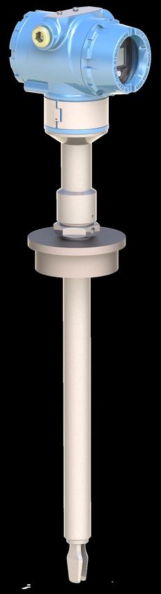
Safety messages

      NOTICE
      Read this manual before working with the product. For personal and system safety, and for optimum product performance,
      ensure you thoroughly understand the contents before installing, using, or maintaining this product.
      For technical assistance, contacts are listed below:

      Customer Central
      Technical support, quoting, and order-related questions.
      •   United States - 1-800-999-9307 (7:00 am to 7:00 pm CST)
      •   Asia Pacific- 65 777 8211

      North American Response Center
      Equipment service needs.
      •   1-800-654-7768 (24 hours a day — includes Canada)
      •   Outside of these areas, contact your local Emerson representative.

          WARNING
      Failure to follow safe installation and servicing guidelines could result in death or serious injury.
      Ensure the level detector is installed by qualified personnel and in accordance with applicable code of practice.
      Use the level detector only as specified in this manual. Failure to do so may impair the protection provided by the level detector.
      The weight of a level detector with a heavy flange and extended fork length may exceed 37 lb. (18 kg). A risk assessment is
      required before carrying, lifting, and installing the level detector.
      For installations in hazardous locations, the level detector must be installed according to the Rosemount 2140 and 2140:SIS Level
      Detectors Product Certifications document.

          WARNING
      Explosions could result in death or serious injury.
      Verify that the operating atmosphere of the level detector is consistent with the appropriate hazardous locations certifications.
      Before connecting a handheld communicator in an explosive atmosphere, ensure that the instruments in the loop are installed in
      accordance with intrinsically safe or non-incendive field wiring practices.
      In explosion-proof/flameproof and non-incendive installations, do not remove the housing covers when power is applied to the
      level detector.
      Both housing covers must be fully engaged to meet flameproof/explosion-proof requirements.

          WARNING
      Electrical shock could cause death or serious injury.
      Avoid contact with the leads and terminals. High voltage that may be present on leads can cause electrical shock.
      Ensure the power to the level detector is off, and the lines to any other external power source are disconnected or not powered
      while wiring the level detector.
      Ensure the wiring is suitable for the electrical current and the insulation is suitable for the voltage, temperature, and environment.

2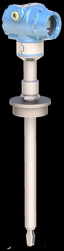
WARNING
Process leaks could result in death or serious injury.
Ensure the level detector is handled carefully. If the process seal is damaged, gas might escape from the vessel (tank) or pipe.

   WARNING
Physical access
Unauthorized personnel may potentially cause significant damage to and/or misconfiguration of end users’ equipment. This could
be intentional or unintentional and needs to be protected against.
Physical security is an important part of any security program and fundamental to protecting your system. Restrict physical access
by unauthorized personnel to protect end users’ assets. This is true for all systems used within the facility.

   CAUTION
Hot surfaces
The flange and process seal may be hot at high process temperatures. Allow to cool before servicing.

   CAUTION
The products described in this document are NOT designed for nuclear-qualified applications.
Using non-nuclear qualified products in applications that require nuclear-qualified hardware or products may cause inaccurate
readings.
For information on Rosemount nuclear-qualified products, contact your local Emerson Sales Representative.

                                                                                                                                   3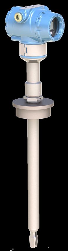
4
Safety Manual                                                                                                                                        Contents
00809-0200-4140                                                                                                                                    March 2021

Contents
Chapter 1           Before you begin........................................................................................................ 7
                    1.1 About this document................................................................................................................... 7
                    1.2 About this product.......................................................................................................................7
                    1.3 Related documents......................................................................................................................8

Chapter 2           Installation and commissioning..................................................................................9
                    2.1 Safety Instrumented System (SIS) certification............................................................................ 9
                    2.2 Safety certified identification....................................................................................................... 9
                    2.3 Installation.................................................................................................................................10
                    2.4 Configuration............................................................................................................................ 10

Chapter 3           Proof tests................................................................................................................19
                    3.1 Overview................................................................................................................................... 19
                    3.2 Comprehensive proof testing.................................................................................................... 20
                    3.3 Partial proof-testing...................................................................................................................22

Chapter 4           Operating constraints.............................................................................................. 25
                    4.1 Specifications............................................................................................................................ 25
                    4.2 Product repair............................................................................................................................26

Appendix A          Terms and definitions...............................................................................................27

Rosemount 2140:SIS Level Detector                                                                                                                                    5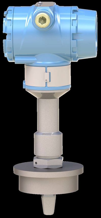
Contents                    Safety Manual
March 2021               00809-0200-4140

6            Rosemount 2140:SIS Level Detector
Safety Manual Before you begin
00809-0200-4140 March 2021
1 Before you begin
1.1 About this document
This document provides information about how to install, commission, and proof test a
Rosemount 2140:SIS Level Detector to comply with Safety Instrumented Systems (SIS)
requirements.
Note
The following conditions must apply:
• The level detector has been installed correctly and completely according to the
instructions in the Reference Manual and Quick Start Guide.
• The installation complies with all applicable safety requirements.
• The operator is trained in local and corporate safety standards.
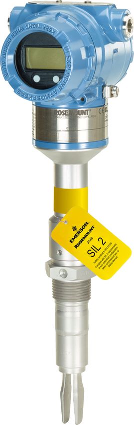
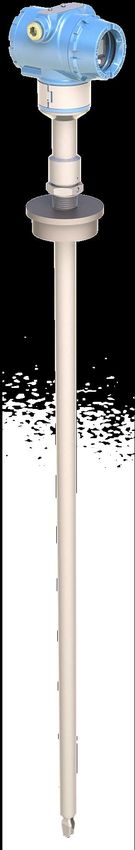
1.2 About this product
The Rosemount 2140:SIS Level Detector consists of a tuned fork with a driver and receiver
element, and integral interface electronics. The level detector is based on the principle
that the resonant frequency of a tuned fork changes when it is immersed in a liquid. The
frequency change is detected and used to switch an electronic output. The device output
is 4-20 mA.
1.2.1 Application examples
Figure 1-1: Example Level Detection Applications
A B C
A. High and low alarm
B. Pump control
C. Overfill prevention
Rosemount 2140:SIS Level Detector 7Before you begin Safety Manual
March 2021 00809-0200-4140
1.3 Related documents
You can find all product documentation at Emerson.com/Rosemount.
For more information, see the following documents:
Table 1-1: Related Documentation
Document Document type
00809-0100-4140 Reference Manual
00813-0100-4140 Product Data Sheet
00825-0100-4140 Quick Start Guide
00825-0200-4140 Product Certifications
8 Rosemount 2140:SIS Level DetectorSafety Manual Installation and commissioning
00809-0200-4140 March 2021
2 Installation and commissioning
2.1 Safety Instrumented System (SIS) certification
For safety instrumented systems usage, the 4-20 mA analog output is used as the primary
safety variable. It is configured to activate the alarm function if an error occurs. The
Rosemount 2140:SIS may be used in high level or low level safety related applications.
The measurement signal used by the logic solver must be the discrete current levels set at
the instrument output used to indicate the sensor condition. A change in liquid level
through the switch point of the level detector results in the user configured discrete
current value being set at the output by the instrument. The HART® protocol must only be
used for setup, calibration, and diagnostic purposes, not for safety critical operation.
The Rosemount 2140:SIS is IEC 61508 certified to:
• Type B low-demand device
• SIL 2 @ HFT = 0
• SIL 3 @ HFT = 1
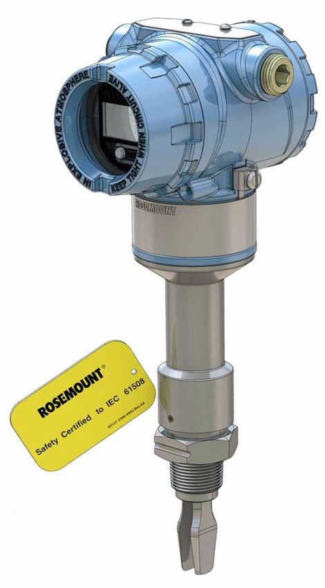
2.2 Safety certified identification
All Rosemount 2140:SIS Level Detectors must be identified as safety certified before
installing into SIS systems.
Procedure
1. Verify the model code starts with "2140F".
2. Verify the software (SW) is V01.01.00 or later.
Figure 2-1: Identification
HW XX . XX . XX
SW XX . XX . XX A
SERIAL No. XXXXXXXXXXXX B
MODEL: 2140FXXXXXXXXXX C
D
E
A. SW version
B. Model code
C. Serial number
D. Yellow stripe for locating device from distance
E. Yellow tag for locating device from distance
Rosemount 2140:SIS Level Detector 9Installation and commissioning Safety Manual
March 2021 00809-0200-4140
2.3 Installation
Refer to the Rosemount 2140 and 2140:SIS Product Data Sheet for the specifications and
Reference Manual for installation instructions.
2.4 Configuration
2.4.1 Hardware configuration for SIS applications
Alarm level switch
Under alarm conditions, the output current is forced to a high or low level beyond the
normal 4 mA to 20 mA operating range.
The Alarm Level hardware switch is set to a 'H' or 'L' position to determine if it is the high or
low alarm current. Figure 2-2 shows the Alarm Level switch inside the housing.
Read-only switch
The Read-Only hardware switch is set to the Locked position to prevent configuration
changes using the optional Local Operator Interface (LOI) or HART® interfaces.
Figure 2-2 shows the Read-Only switch inside the housing.
Figure 2-2: Alarm Level and Read-only Switches
Without LOI display With LOI display
A
B
A. Alarm Level switch
B. Read-only switch
Related information
High and low alarm levels
10 Rosemount 2140:SIS Level DetectorSafety Manual Installation and commissioning
00809-0200-4140 March 2021
2.4.2 Software configuration for SIS applications
Sensor operating mode
The level detector has three sensor operating modes:
• Normal (default for Rosemount 2140)
— Sensor fault detection is not enabled. Do not select this option for SIS applications.
• Enhanced, Fault=Wet (default for Rosemount 2140:SIS)
— The level detector is forced to indicate a wet fork in a fail-safe state.
• Enhanced, Fault=Dry
— The level detector is forced to indicate a dry fork in a fail-safe state.
Sensor output delay
When there is a detected change in the condition of the fork, from wet-to-dry or dry-to-
wet, the Sensor Output Delay parameter can action a delay of up to 3600 seconds before
the change of state is indicated. The default delay is one second.
Depending on the application, a suitable delay can prevent constant switching of the
output current. If, for example, there are waves in a tank, then there may be splashes
causing intermittently detected changes in process conditions. The sensor output delay
ensures that the fork is dry or wet for a suitable period before switching the output
current.
Media density selection
The level detector is capable of operating with liquid densities ranging from 400 to 1300
kg/m3. Use the Media Density Selection parameter to select a density range for the
process level application. Possible settings are shown in Table 2-1.
Table 2-1: Media Density Settings
Setting Range
0.4 – 0.6 SG 400 to 600 kg/m3
0.5 – 0.9 SG 500 to 900 kg/m3
0.8 – 1.3 SG 800 to 1300 kg/m3
Sensor fault delay
When the level detector is operating in Enhanced Mode and detects a fork sensor fault, the
Sensor State parameter indicates a fault state after a delay.
The default setting is 5 seconds. It can be set to a value in the range 0 to 3600 seconds.
Note
When the level detector is operating in Normal mode, a fork sensor fault is not detected
and Sensor State continues to indicate a valid state.
Rosemount 2140:SIS Level Detector 11Installation and commissioning Safety Manual
March 2021 00809-0200-4140
Current output operating mode
Options to select are:
• Dry on
• Wet on
The Sensor State variable uses these settings of "Dry on" and "Wet on" to associate with
when the Output State variable is indicating ‘on’ (1.0).
Configuration examples
Empty-vessel detector application
Figure 2-3 shows an empty-vessel detector application where a low level alarm can be
indicated by the output being switched on. This should also be the fail-safe state when a
fault occurs (dry=fault). The output switches off again when the liquid level rises and
immerses the fork.
Figure 2-3: Low Level Alarm ('Dry On' Configuration)
A
A. When configured to operate in 'Dry On' mode, the output switches 'on' when the liquid
level falls below the fork.
12 Rosemount 2140:SIS Level DetectorSafety Manual Installation and commissioning
00809-0200-4140 March 2021
Application with a full-vessel detector and an empty-vessel detector
Figure 2-4 shows an application with a full-vessel detector and an empty-vessel detector.
Level alarms are indicated by a Rosemount 2140:SIS switching its output off. The top-
mounted level detector should be configured to have a fail-safe state of a wet fork
(wet=fault). The side-mounted level detector needs a fail-safe state of a dry fork
(dry=fault).
Figure 2-4: High and Low Level Alarms ('Wet On' and 'Dry On' Configurations)
A
B
A. The level detector is configured to operate in 'Dry On' mode. When the liquid level rises
above the fork, the system output is switched off.
B. The level detector is configured to operate in 'Wet On' mode. When the liquid level falls
below the fork, the system output is switched off.
Current output type
The current output can be configured to switch between standard instrument levels 8 and
16 mA and 4 and 20 mA. In addition, a custom mode is provided, where the user can
define, between 4 and 20 mA, custom current levels via the Custom On Current and
Custom Off Current parameters to indicate wet and dry conditions, dependent on the
setting of the Current Output Operating Mode.
Rosemount 2140:SIS Level Detector 13Installation and commissioning Safety Manual
March 2021 00809-0200-4140
Switched 4 and 20 mA output
The Current Output Type parameter can be configured to switch the output current
between 4 mA and 20 mA levels.
Figure 2-5 shows the effects on the current output when the Current Output Type is set to
'4 and 20 mA'. The Current Output Operating Mode is 'Dry On', custom alarm levels are
selected and set to 3.6 mA, and the alarm level hardware switch is set to 'L'.
Figure 2-5: Current Output Type Set to 4 and 20 mA
24
20
16
8
4
3.6
A B C
A. Output is 'on' when the fork is dry
B. Output is 'off' when the fork is wet
C. Output is in a fail-safe state (fault=wet)
14 Rosemount 2140:SIS Level DetectorSafety Manual Installation and commissioning
00809-0200-4140 March 2021
Switched 8 and 16 mA output
The Current Output Type parameter can be configured to switch the output current
between 8 mA and 16 mA levels.
Figure 2-6 shows the effects on the current output when the Current Output Type
parameter is set to '8 and 16 mA'. The Current Output Operating Mode is 'Wet On',
custom alarm levels are selected and set to 23 mA, and the alarm level hardware switch is
set to 'H'.
Figure 2-6: Current Output Type Set to 8 and 16 mA
24
20
16
8
4
3.6
A B C
A. Output is 'off' when the fork is dry
B. Output is 'on' when the fork is wet
C. Output is in a fail-safe state (fault=wet)
Rosemount 2140:SIS Level Detector 15Installation and commissioning Safety Manual
March 2021 00809-0200-4140
Custom switched output
The Current Output Type parameter can be configured to switch the output current
between two customer-defined levels.
Figure 2-7 shows the effects on the current output when the Current Output Type
parameter is set to 'Custom'. The Current Output Operating Mode is 'Wet On', the
Custom Off Current is 5 mA, the Custom On Current is 15 mA, Rosemount alarm levels
are selected, and the Alarm Level hardware switch is set to 'H'.
Figure 2-7: Current Output Type Set to Custom
24
20
16
8
4
3.6
A B C
A. Output is 'off' when the fork is dry
B. Output is 'on' when the fork is wet
C. Output is in a fail-safe state (fault=wet)
16 Rosemount 2140:SIS Level DetectorSafety Manual Installation and commissioning
00809-0200-4140 March 2021
High and low alarm levels
The software settings in Table 2-2 are used together with the Alarm Level hardware setting
to specify a fixed output current under an alarm condition.
The "NAMUR" and "Rosemount" alarm levels have preset fixed values that cannot be edited.
When “Custom” alarm levels is selected, fixed output current values must be entered
using High and Low Alarm Current parameters.
Table 2-2: Alarm Current Levels
Alarm and saturation type Low alarm level (mA) High alarm level (mA)
NAMUR ≤ 3.6 (option code C5) ≥ 22.5 (option code C4)
Rosemount ≤ 3.75 (option code C8) ≥ 21.75 (default)
Custom (option code C1) 3.6 – 3.8 20.2 – 23.0
Rosemount 2140:SIS Level Detector 17Installation and commissioning Safety Manual March 2021 00809-0200-4140 18 Rosemount 2140:SIS Level Detector
Safety Manual                                                                                           Proof tests
00809-0200-4140                                                                                         March 2021

3                     Proof tests
3.1                   Overview
                      The Rosemount 2140:SIS must be tested at regular intervals to reveal faults which are
                      undetected by automatic diagnostics. It is the user's responsibility to choose the type of
                      testing and the frequency of these tests.
                      Results from periodic proof tests shall be recorded and periodically reviewed. If an error is
                      found in the safety functionality, the device shall be put out of operation and the process
                      shall be kept in a safe state by other measures.
                      Note
                      For a valid result, always perform the proof test on the product that will be stored in the
                      tank while the device is in operation.

3.1.1                 Suggested proof tests
                      The following proof tests are suggested:
                      • (A) Comprehensive proof test
                      • (B) Partial proof test
                      Table 3-1 can be used as a guidance for selecting the appropriate proof test.
Table 3-1: Suggested Proof Tests
Proof     Device(1)                Proof test   Remaining                 Test coverage                   Can be
test #                             coverage     dangerous,                                              performed
                                   (%) of DU    undetected     Output      Measurement       Sensor      remotely
                                                failures      circuitry     electronics

          2140:SIS T0 Dry On       55%          7 FIT
          2140:SIS T0 Wet On       59%          7 FIT
A                                                                Yes            Yes            Yes          No
          2140:SIS T1 Dry On       54%          5 FIT
          2140:SIS T1 Wet On       56%          6 FIT
          2140:SIS T0 Dry On       20%          12 FIT
          2140:SIS T0 Wet On       26%          12 FIT
B                                                                Yes            Yes            No           Yes
          2140:SIS T1 Dry On       26%          9 FIT
          2140:SIS T1 Wet On       26%          10 FIT

(1) T0 = Standard terminal block
    T1 = Transient protection terminal block

                      Related information
                      Comprehensive proof testing
                      Partial proof-testing

Rosemount 2140:SIS Level Detector                                                                                   19
Proof tests Safety Manual
March 2021 00809-0200-4140
3.1.2 Proof test interval
The time intervals for proof testing are defined by the SIL verification calculation (subject
to the PFDAVG). The SIL verification calculation is an analytical method to calculate an
appropriate proof test interval for the specific safety function based on equipment’s
reliability and required risk reduction for the specific SIF.
The proof tests must be performed more frequently than or as frequently as specified in
the SIL verification calculation, in order to maintain the required safety integrity of the
overall SIF.
3.1.3 Tools required
• HART host/communicator
• Current meter
• Safety logic solver
3.2 Comprehensive proof testing
Comprehensive proof-testing requires a different method to local and remote partial
proof-testing. It takes several hours to perform with all safety measures being followed.
3.2.1 Impact on SIF and process
In order to achieve the product safe state, the sensor must be either removed from or
immersed in the process medium, depending on the operating mode. The process cannot
be allowed to operate whilst the proof test is being performed.
3.2.2 Perform comprehensive proof test
The suggested testing consists of setting the output to a maximum and minimum, and
checking the sensor and associated analog output levels.
Procedure
1. Inspect the accessible parts of the level detector for any leaks or damage.
2. Bypass the safety function and take appropriate action to avoid a false trip.
3. Using Loop Test, simulate the high alarm current output, and verify that the analog
current reaches that value.
4. Using Loop Test, simulate the low alarm current output, and verify that the analog
current reaches that value.
5. Change process conditions for the fork to experience the configured alarm
condition, and verify the analog output reaches the configured ‘off’ output current
within the expected time period.
See Transmitter response time for help with this.
20 Rosemount 2140:SIS Level DetectorSafety Manual Proof tests
00809-0200-4140 March 2021
6. Change process conditions for the fork to experience the normal (dry on or wet on)
condition, and verify the analog output reaches the configured ‘on’ output current
within the expected time period.
See Transmitter response time for help with this.
7. Remove the bypass and otherwise restore normal operation.
Related information
Loop testing
3.2.3 Loop testing
Start a loop test using AMS Device Manager
Procedure
1. Select Service Tools → Simulate.
2. Click on Loop Test.
3. Follow on-screen instructions to perform a loop test.
Start the loop test using a handheld communicator
Procedure
1. From the Home screen, select Service Tools.
2. Select Simulate → Loop Test.
3. Follow on-screen instructions to perform a loop test.
Start the loop testing using a LOI
Procedure
1. Press any LOI configuration button to activate the menu.
2. Scroll down ( ) and then select TEST ( ) .
3. Scroll down ( ) and then select LOOP TEST ( ) .
4. Select a loop test option:
• Select SET 4MA (i.e. 4 mA).
• Select SET 20MA (i.e. 20 mA).
• Select SET CUSTOM.
5. Follow on-screen instructions to perform the loop test.
6. Exit the menu system by either waiting one minute for the EXIT MENU? prompt, or
scrolling down menus to find and select BACK TO MENU and EXIT MENU.
Rosemount 2140:SIS Level Detector 21Proof tests Safety Manual
March 2021 00809-0200-4140
3.3 Partial proof-testing
The level detector has local and remote partial proof-testing support as standard.
3.3.1 Impact on SIF and process
The process cannot be allowed to operate whilst the proof test is being performed.
3.3.2 Perform partial proof test
The suggested testing exercises the signal processing and output, but does not test the
sensor.
Procedure
1. Inspect the accessible parts of the level detector for any leaks or damage.
2. Bypass the safety function and take appropriate action to avoid a false trip.
3. Start the partial proof-test procedure.
4. Verify the analog output reaches the configured:
a) Low alarm current - for one quarter of the proof-test duration.
b) ‘Off’ output current - for one quarter of the proof-test duration.
c) ‘On’ output current - for one quarter of the proof-test duration.
d) High alarm current - for one quarter of the proof-test duration.
5. Remove the bypass and otherwise restore normal operation.
Related information
Starting local partial proof-testing
Starting remote partial proof-testing
Duration of partial proof-test
3.3.3 Starting local partial proof-testing
By default, the partial proof-testing sequence is not started at every power-up. It can be
started by an operator using the Local Operator Interface (LOI).
Procedure
In the menu system, select TEST → PROOF TEST or, when no LOI is not fitted, by using the
single external push-button fitted to the top of the level detector (underneath the
movable nameplate).
22 Rosemount 2140:SIS Level DetectorSafety Manual Proof tests
00809-0200-4140 March 2021
3.3.4 Starting remote partial proof-testing
Start partial proof test using AMS Device Manager
Procedure
1. Select Service Tools → Maintenance → Test.
2. Select Partial Proof-Test and follow the on-screen instructions.
Start partial proof test using a handheld communicator
Procedure
1. From the Home screen, select Service Tools.
2. Select Maintenance → Operation → Partial Proof Test.
3. Follow on-screen instructions during the partial proof-test.
3.3.5 Duration of partial proof-test
The Proof-Test Duration parameter determines the duration of the whole partial proof-
testing sequence.
Four steps performed are:
• Low Alarm Current step
— The analog output current is overridden to the Low Alarm level (as configured).
• Off Current step
— The analog output current is overridden to the level of the ‘off’ switched output
state (as configured).
• On Current step
— The analog output current is overridden to the level of the ‘on’ switched output
state (as configured).
• High Alarm Current step
— The analog output current is overridden to the High Alarm level (as configured).
Note
Setting a value of “0 s” (zero seconds) results in the analog output not being exercised
during the proof-test. Only a diagnostic check of the device is performed in this case.
Rosemount 2140:SIS Level Detector 23Proof tests Safety Manual
March 2021 00809-0200-4140
Configure proof test function using AMS Device Manager
Procedure
1. Select Configure → Manual Setup → Operation.
2. Edit the Duration field if changing the setting for how long the partial proof-test
lasts.
3. In Start-up Proof Test list, select Enabled or Disabled.
Configure proof test function using a handheld
communicator
Procedure
1. From the Home screen, select Service Tools.
2. Select Manual Setup → Operation → Proof Test.
3. Choose the partial proof-test parameter to change:
a) Select Duration for setting how long the partial proof-test lasts.
b) Select Start-up Proof-Test for setting if partial proof-testing at start-up is
enabled or disabled.
Configure proof test function using the LOI
Procedure
1. Press any LOI configuration button to activate the menu.
2. Scroll down ( ) and then select EXTENDED MENU ( ).
3. Scroll down ( ) and then select PROOF TEST ( ).
4. Choose the proof-test parameter to change:
a) Select DURATION for setting how long the partial proof-test lasts.
b) Select START-UP for setting if partial proof-testing at start-up is enabled or
disabled
5. Exit the menu system by either waiting one minute for the EXIT MENU? prompt, or
scrolling down menus to find and select BACK TO MENU and EXIT MENU.
24 Rosemount 2140:SIS Level DetectorSafety Manual Operating constraints
00809-0200-4140 March 2021
4 Operating constraints
4.1 Specifications
The Rosemount 2140:SIS must be operated according to the functional and performance
specifications provided in the Rosemount 2140 and Rosemount 2140:SIS Product Data
Sheet.
4.1.1 Failure rate data
The FMEDA report includes failure rate data, assessment details, and assumptions
regarding failure rate analysis.
4.1.2 Transmitter response time
The transmitter response time for all output types is the greater of 10 seconds or the
selected seconds delay using the output delay setting.
Table 4-1: Transmitter response time
Current Supply voltage Safety alarm Transmitter Switch point Switch point
Output levels (leakage response (water)(3) (other
Type currents)(1) time(2) liquid)(4)
4-20 mA 10.5 to 42.4 Vdc 3.6 mA 10 s minimum 11 to 15 mm 0 to 30 mm
(1) Logic solver trip levels should be set higher than these values in order to ensure reliable trips.
(2) The transmitter response time is the greater of 10 seconds or the configured seconds delay of the
Output Delay setting.
(3) Operating (switching) point measured from lowest point of fork when liquid is water.
(4) Operating (switching) point measured from lowest point of fork when liquid is not water.
Related information
Sensor output delay
4.1.3 Diagnostic test interval
< 60 min
4.1.4 Useful lifetime
50 years
• based on worst case component wear-out mechanisms
• not based on wear-out of process wetted materials
Rosemount 2140:SIS Level Detector 25Operating constraints Safety Manual
March 2021 00809-0200-4140
4.2 Product repair
The Rosemount 2140:SIS is repairable by major component replacement. All failures
detected by the device diagnostics or by the proof test must be reported. Feedback can be
submitted electronically at Go.EmersonAutomation.com/Contact-Us (Contact Us).
26 Rosemount 2140:SIS Level DetectorSafety Manual Terms and definitions
00809-0200-4140 March 2021
A Terms and definitions
λDU Dangerous Undetected
λDD Dangerous Detected
λSU Safe Undetected
λSD Safe Detected
Diagnostic test The time from when a dangerous failure/condition occurs until the
interval device has set the safety related output in a safe state (total time
required for fault detection and fault reaction).
Element Term defined by IEC 61508 as “part of a subsystem comprising a
single component or any group of components that performs one or
more element safety functions”
FIT Failure In Time per billion hours
FMEDA Failure Modes, Effects and Diagnostic Analysis
®
HART protocol Highway Addressable Remote Transducer
HFT Hardware Fault Tolerance
High demand The safety function is only performed on demand, in order to transfer
mode the EUC (Equipment Under Control) into a specified safe state, and
where the frequency of demands is greater than one per year (IEC
61508-4).
Low demand The safety function is only performed on demand, in order to transfer
mode the EUC into a specified safe state, and where the frequency of
demands is no greater than one per year (IEC 61508-4).
PFDAVG Average Probability of Failure on Demand
PFH Probability of dangerous Failure per Hour: the term "probability" is
misleading, as IEC 61508 defines a rate.
Proof test The effectiveness of a proof test is described using the coverage
coverage factor factor which specifies the share of detected dangerous undetected
failures (λDU). The coverage factor is an indication of a proof test’s
effectiveness to detect dangerous undetected faults.
Safety deviation The maximum allowed deflection of the safety output due to a failure
within the device (expressed as a percentage of span).
Any failure causing the device output to change less than the Safety
Deviation is considered as a "No Effect" failure. All failures causing the
device output to change more than the Safety Deviation and with the
device output still within the active range (non-alarm state) are
considered dangerous failures.
Rosemount 2140:SIS Level Detector 27Terms and definitions Safety Manual
March 2021 00809-0200-4140
Note
The Safety Deviation is independent of the normal performance
specification or any additional application specific measurement
error.
SIF Safety Instrumented Function
SIL Safety Integrity Level – a discrete level (one out of four) for specifying
the safety integrity requirements of the safety instrumented
functions to be allocated to the safety instrumented systems. SIL 4
has the highest level of safety integrity, and SIL 1 has the lowest level.
SIS Safety Instrumented System – an instrumented system used to
implement one or more safety instrumented functions. An SIS is
composed of any combination of sensors, logic solvers, and final
elements.
Systematic A measure (expressed on a scale of SC 1 to SC 4) of the confidence
capability that the systematic safety integrity of an element meets the
requirements of the specified SIL, in respect of the specified element
safety function, when the element is applied in accordance with the
instructions specified in the compliant item safety manual for the
element.
Transmitter The time from a step change in the process until transmitter output
response time reaches 90% of its final steady state value (step response time as per
IEC 61298-2).
Type B device Complex device using controllers or programmable logic, as defined
by the standard IEC 61508.
Useful lifetime Reliability engineering term that describes the operational time
interval where the failure rate of a device is relatively constant. It is
not a term which covers product obsolescence, warranty, or other
commercial issues.
The useful lifetime is highly dependent on the element itself and its
operating conditions (IEC 61508-2).
28 Rosemount 2140:SIS Level DetectorSafety Manual 00809-0200-4140 March 2021 Rosemount 2140:SIS Level Detector 29
00809-0200-4140
                                                                         Rev. CA
                                                                           2021

For more information: www.emerson.com
©2021 Emerson. All rights reserved.

Emerson Terms and Conditions of Sale are available upon
request. The Emerson logo is a trademark and service mark of
Emerson Electric Co. Rosemount is a mark of one of the
Emerson family of companies. All other marks are the property
of their respective owners.
You can also read