Apogee Imaging Systems Camera Installation Guide
←
→
Page content transcription
If your browser does not render page correctly, please read the page content below
Apogee Imaging Systems
        Camera Installation Guide

Version 1.9
Apogee Imaging Systems

Disclaimer

Apogee Imaging Systems, Inc. assumes no liability for the use of the information contained in this
document or the software which it describes. The user assumes all risks. There is no warranty of
fitness for a particular purpose, either express or implied.

The information contained in this document is assumed to be correct, but in no event shall
Apogee Imaging Systems Inc. be held responsible for typographical errors or changes in the
software not reflected in this document.

The specifications contained in this document are subject to change without notice.

Support

The Apogee Imaging Systems Camera Installation Guide is provided as a courtesy to our
customers, and comes without warranty of fitness for any purpose or application, either
expressed or implied. The user assumes all risk for the use of the information contained in this
document and the software it describes.

Copyright © 2003-2014 Apogee Imaging Systems, Inc.
All rights reserved.

Alta, Aspen and Ascent are registered trademarks of Apogee Imaging Systems, Inc.

The section “Using MaxIm DL/CCD” contains material copyright of Diffraction Limited.

The section “Installing Micro-Manager (µManager) Software” contains material copyright of Vale
Lab, UCSF.

All other trademarks mentioned in this document are the property of their respective owners, and
are used herein solely for informational purposes only.

Apogee Imaging Systems, Inc.
151 N. Sunrise Road, Suite 902
Roseville, CA 95661

(916) 218-7450
(916) 218-7451 (Fax)
www.ccd.com

Camera Installation Guide                                                             Page 2 of 25
Apogee Imaging Systems

1 Introduction and Setup
Thank you for purchasing an Apogee camera system. This installation guide covers installing,
discovering, and configuring Apogee cameras on the Microsoft Windows family of operating
systems. Apogee USB and Ethernet camera systems are designed and tested using the
Windows XP 32 bit, Vista 32 and 64 bit and Windows 7 32 and 64 bit operating systems, in order
to assure the best possible user experience and performance. Apogee Imaging Systems, Inc. has
not verified or tested, and has no plans to support, cameras on previous versions of Microsoft
Windows.

Apogee Imaging Systems recommends the following process for getting your new camera up and
running as quickly as possible:
        1) Install Maxim DL/CCD application software
        2) Install/Update Apogee Drivers
        3) Apply Power and Data Connections to the USB or Network camera
        4) Begin using your Apogee camera!

1.1 Install MaxIm DL/CCD
Your Apogee camera may have included a copy of MaxIm DL/CCD image capture and
processing software, developed by Diffraction Limited. If you will be using the MaxIm DL/CCD
software, we recommend that you install it prior to setting up your Apogee camera. Please see
the MaxIm documentation for specific instructions related to installation of this software.

Apogee cameras are supported by MaxIm DL/CCD version 3.21 and beyond.

1.2 Install/Update Apogee Camera Driver
1.2.1 Windows XP
WARNING: Do not connect your Apogee device to a PC before installing the drivers. If you do
and the "Add New Hardware Wizard" appears, please select the Cancel button.

Windows XP users must install .NET framework version 3.5 with Service Pack 1. Note: This
specific .Net framework 3.5 with SP1 is required for Apogee Imaging Systems drivers, and
older/newer versions will not work. This framework is included with Windows Vista and Windows
7 operating systems.

To install the .NET framework version 3.5 with Service Pak 1:
        1): Online Installer (recommended): approx. 3 MB
        http://www.microsoft.com/en-us/download/details.aspx?id=22
        For computers that are connected to the internet, this small installer downloads the files it
        needs to install the .NET framework at runtime.

        2): Offline Installer: approx. 232 MB
        http://www.microsoft.com/en-us/download/details.aspx?id=25150
        For computers that are not connected to the internet, this is a larger installation package
        with all needed files.

Camera Installation Guide                                                               Page 3 of 25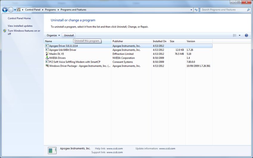
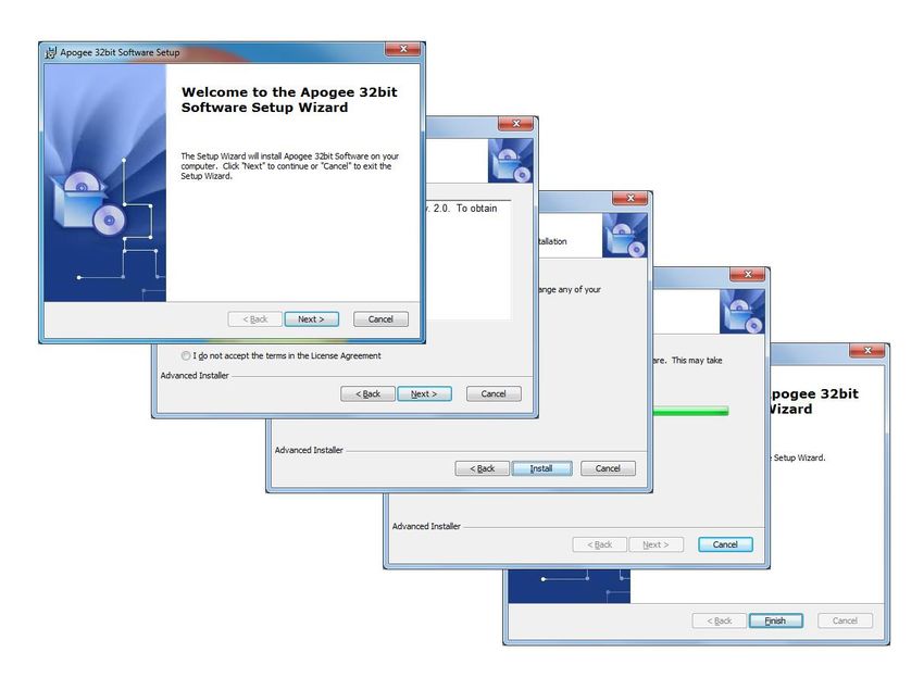
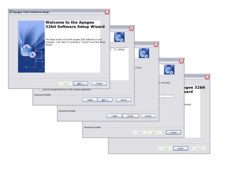
Apogee Imaging Systems

Make sure your Windows user account has administrator privileges. Double click on the
setupApogeeSoftware.exe.

If you see the following error dialog, then please refer to section 1.3 Upgrading from Version 3 to
Version 5 Software below. After removing v3 software, try executing the
setupApogeeSoftware.exe again.

Follow the installation wizard instructions.

Camera Installation Guide                                                              Page 4 of 25
Apogee Imaging Systems

Upon successful driver installation connect the Apogee camera to your PC. The "New Hardware
Wizard" window will appear. On the dialog select the "No, not a this time" radio button. Press the
"Next" button.

Make sure the "Install software automatically (recommended)" radio button is selected and press
"Next”.

The New Hardware Wizard states it has completed installing software for the Apogee USB
Camera and USB Filter Wheel. Press the "Finish" button.

The drivers for your Apogee camera are now installed on your PC.

Camera Installation Guide                                                            Page 5 of 25
Apogee Imaging Systems

1.2.2 Windows Vista/7
WARNING: Do not connect your Apogee device to a PC before installing the drivers. If you do
and the "Add New Hardware Wizard" appears, please select the Cancel button.

Make sure your Windows user account has administrator privileges. Right click on the
setupApogeeSoftware.exe, and select “Run as Administrator.”

If you see the following error dialog, then please refer to section 1.3 Upgrading from Version 3 to
Version 5 Software below. After removing v3 software, try executing the
setupApogeeSoftware.exe again.

Camera Installation Guide                                                              Page 6 of 25
Apogee Imaging Systems

Follow the installation wizard instructions.

Upon successful driver installation connect your camera to the PC. Watch the message balloon
in the lower right corner state the OS, search for and successfully install the drivers for the
Apogee USB camera.

The drivers for your Apogee camera are now installed on your PC.

Camera Installation Guide                                                           Page 7 of 25
Apogee Imaging Systems

1.3 Upgrading from Version 3 to Version 5 Software
Due to installer incompatibility v3 software must be manually uninstalled first, before upgrading to
v5 software.

For XP go to the Add and Remove Programs dialog from the Control Panel and remove the
Apogee Driver 3.*.*.* software package as shown below.

For Windows Vista/7 Programs dialog from the Control Panel and uninstall the Apogee Driver
3.*.*.* software package as shown below.

Camera Installation Guide                                                              Page 8 of 25
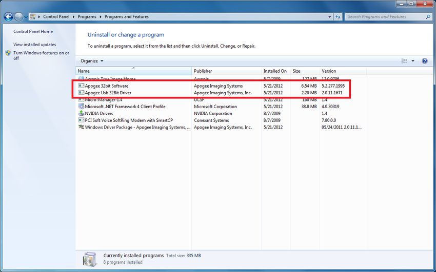
Apogee Imaging Systems

1.4 Uninstalling Apogee Software
Using the Windows control panel is the recommend method for completely uninstalling Apogee
software.

For XP go to the Add and Remove Programs dialog from the Control Panel and remove the
Apogee USB 64 or 32 bit Driver and the Apogee 32bit Software.

For Windows Vista/7 Programs dialog from the Control Panel and remove the Apogee USB 64
or 32 bit Driver and the Apogee 32bit Software.

Camera Installation Guide                                                       Page 9 of 25
Apogee Imaging Systems
2 Network Camera Settings (Aspen)
Apogee Aspen cameras have network settings
which can be configured through any common
web browser. If you do not already know the
address, you can use the ApogeeCameraInfo
utility to help locate the camera. Aspen cameras
ship with DHCP turned on by default, so in order
to discover via Ethernet the camera must be on
a network with a router to assign it an IP
address.
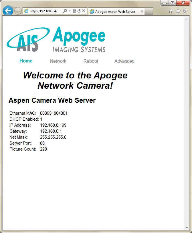
Once you have obtained the IP address, enter it
into the Address bar of your internet browser.
The camera will reply with its own web page, as
shown in the screen capture below.
The camera Home page shows the network
settings and picture count of the camera. There
are also links to adjust the network settings,
reboot the interface, and adjust advanced
settings. When you click one of these links, the
camera will present you with an authentication
dialog box.
The default user name is admin. The default
password is password. Enter these into their
respective fields and press the OK button.
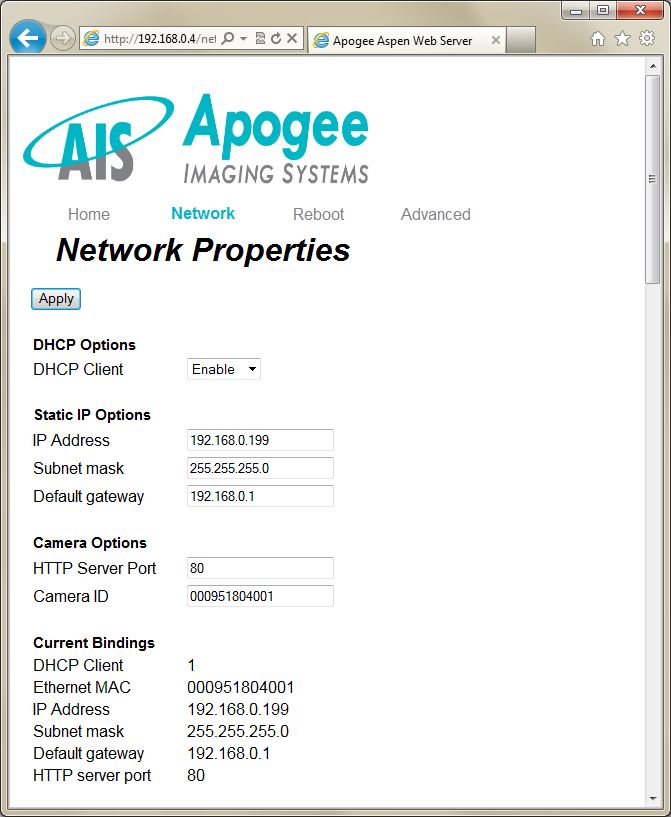
The Network page contains the network
settings for the camera. From this page, the
camera can be configured with a static IP
address. For the camera to be discoverable with
a static IP address, the camera must be on the
same network subnet as the computer doing the
discovery. After applying changes, either go to
the reboot page and reboot the web server on
the camera or power cycle the camera.
Camera Installation Guide Page 10 of 25Apogee Imaging Systems
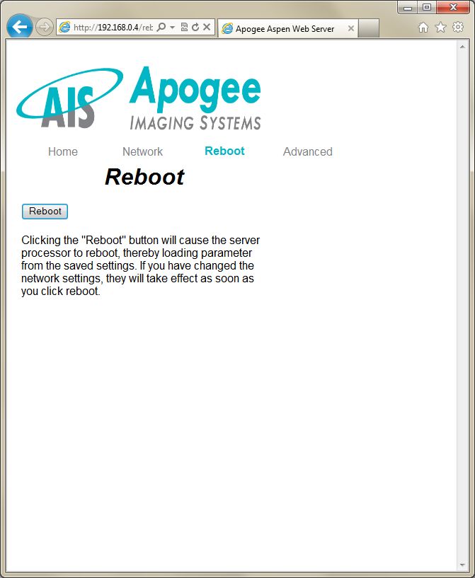
The Reboot page has a button to reboot the
web server on the camera. When rebooting,
the web server will load parameters from
the saved settings. If you have changed
network settings, they will take effect as
soon as you click reboot.
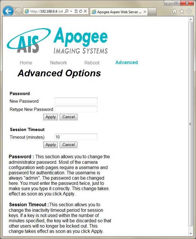
The Advanced page is used for setting a
new password on the camera system. This
page also contains a network timeout
number. The timeout can be used to control
how long a session can remain inactive
before it is automatically closed. This is
useful when the camera is in a remote
location, and being controlled by multiple
users. By setting an appropriate timeout
value, a user will not inadvertently retain
control of the camera system because the
session was never closed.
Camera Installation Guide Page 11 of 25Apogee Imaging Systems
3 Network Camera Settings (Alta)
Apogee Alta Ethernet cameras are configured through any common web browser on the
computer. In order to access the camera settings, you need to know the camera’s IP address. If
you do not already know the address, you can use the ApogeeCameraInfo utility to help locate
the camera.
Once you have obtained the IP address, enter it into the Address bar of your Internet browser.
The camera will reply with its own web page of settings, as shown in the screen capture below.
The camera home page contains a
snapshot of useful information about the
system, including the number of images
the system has captured, hours it has
been operational, and versions of the
internal firmware. This information may
assist Apogee’s technical support, should
you ever require service on your camera
system.
The camera home page also contains
links to other page for configuring
network settings, serial ports, reboots,
etc. When you click one of these links,
the camera will present you with an
authentication dialog box.
The default user name is admin. The
default password is configure. Enter
these into their respective fields and
press the OK button.
.
Camera Installation Guide Page 12 of 25Apogee Imaging Systems
The Network page contains the TCP
settings for the camera. From this page,
the camera can be configured for a static
IP network setup. Also on this page, the
camera name can be selected (the
camera name/ID defaults to the system’s
Ethernet MAC address).
The Serial page lists all of the settings
related to controlling the camera’s on-
board serial ports. The user can switch
between Serial Port A and Serial Port B
by changing the port from the drop down
list.
Camera Installation Guide Page 13 of 25Apogee Imaging Systems
The Password page is used for setting a
new password on the camera system.
This page also contains a network
timeout number. The timeout can be
used to control how long a session can
remain inactive before it is automatically
closed. This is useful when the camera
is in a remote location, and being
controlled by multiple users. By setting
an appropriate timeout value, a user will
not inadvertently retain control of the
camera system because the session was
never closed.
The Reboot page may be used to issue
a software reboot to the camera system.
This may be used as an attempt to clear
a camera network error, although a
power cycle is the most thorough
solution.
Camera Installation Guide Page 14 of 25Apogee Imaging Systems
The Advanced page is primarily used for
updating the camera’s firmware. This
page can also be used for opening and
closing camera sessions, or sending
simple read/write operation to verify
connectivity.
The Help page contains useful
information regarding the usage of the
other configuration web pages, and how
to modify the camera settings.
Consult the Help page for additional
details regarding the configuration of
your Alta network camera.
Camera Installation Guide Page 15 of 25Apogee Imaging Systems 4 Using MaxIm DL/CCD MaxIm DL/CCD, a product from Diffraction Limited, is a powerful camera control and image processing package. The MaxIm DL/CCD software package has an extensive user’s guide, which provides details into setting up the software and getting started. This section covers a quick reference of the specific Alta functionality in MaxIm. The information in this section contains specific MaxIm DL/CCD screenshots. These screenshots were correct and accurate as of MaxIm v5.06, the current shipping version at the time of writing this document. It is possible that users with other versions of MaxIm DL/CCD may notice slight layout changes from what is described here. To begin, consult your MaxIm documentation and launch the MaxIm CCD Control window. This window contains a Setup button. Click the Setup button and then select “Apogee USB/Net” from the list of camera models. For this driver, please select Apogee USB/Net on the Setup tab. All settings for the Apogee camera are in the Apogee Configuration dialog, accessed from the Advanced... button. This dialog is also available while the camera is connected, by clicking the Options button on the Settings Tab and selecting the Camera Settings command. The first step is to specify the location of the camera. For cameras with a network interface, select Ethernet, enter the IP address of the camera, and set Device Number to its TCP port number. If the camera is selected as USB, only the Device Number control is available; set it to the camera identifying number, as enumerated by the operating system. While the camera is connected, the Interface controls are not available; they are replaced by a Status area. If you do not know the location of the camera, you can search for it using the Discover button. See below for an explanation of the camera discovery feature. Camera Installation Guide Page 16 of 25
Apogee Imaging Systems

Alta cameras connected via USB can operate in two Digitization modes. The Fast mode
provides the highest speed, while the Normal mode provides the highest dynamic range.
Cameras connected via Ethernet support only Normal mode.

Fan Setting controls the camera's fan speed. Higher speeds provide better cooling, but may
result in slightly more noise and vibration.

The Configure… button in the Advanced Settings group allows you to access some advanced
camera control parameters, described below. Note that most of these are intended for laboratory
environments, and inappropriate use may adversely affect camera performance and image
quality.

Color Synthesis is used to adjust automatic color generation settings. Some cameras include
Bayer matrix color filters, and are capable of "one shot color". If the Bayer matrix is not properly
aligned, the color may come out wrong. This can be corrected adjusting the X and Y offset
controls. The Use Bgd option automatically tries to adjust the background level to neutral during
the conversion process.

The Exposure and Shutter Options include a camera Mode dropdown whose entries depend
on the specific camera in use. In Normal mode the software controls both the start time and
duration of the exposure. In TDI (Time Delayed Integration) mode, the camera operates
continuously, shifting out new row of data at a specified interval: this is appropriate if the image is
moving smoothly across the CCD sensor. In Kinetics mode the sensor must be masked so that a
specified number of full-width but reduced-height images known as sections can be rapidly
acquired on a single CCD frame. Readout occurs only after all requested sections have been
imaged. For further information, consult the documentation for your camera.

For cameras with firmware v17 and later, the exposure process can be further modified by the
Exposure Triggering options. The instrument waits for a TTL signal pulse before starting the
exposure if First is checked. A separate pulse is required for each subsequent TDI row or

Camera Installation Guide                                                               Page 17 of 25
Apogee Imaging Systems

Kinetics section if Next is checked. Cameras with earlier firmware do not support TDI or Kinetics,
but provide a separate Triggered exposure mode equivalent to Normal with First checked.

The next two options modify the duration of the exposure. External Shutter Signal allows the
shutter to be gated open by an external TTL-level signal, with readout occurring at the trailing
edge of this pulse. Ext. Shutter and Readout is similar but readout is controlled by a separate
TTL-level signal, allowing the shutter to open and close more than once during the same
exposure. In either external shutter mode, the Enable Amp Output checkbox disables the CCD
voltage while the shutter strobe input is high.

IO Port Settings displays the Apogee Camera I/O Port Settings dialog box. This allows you to
configure each I/O pin for a predefined function. These should be self-explanatory; for advanced
use please contact Apogee Imaging Systems for assistance.

Open Shutter opens the shutter for inspection or cleaning.

The two Status Indicator lights can be configured to provide basic status information. To prevent
light contamination under very low-light imaging conditions, you can select OFF when exposing.
You can also select Always OFF or Always ON.

The two Light Emitting Diodes (LED A and LED B) can be configured individually. They can be
set to illuminate when the camera is in Expose mode (unless disabled by OFF when exposing),
when the camera is Active, during Flushing to remove charge from the array, at Wait Trigger to
show when the camera is waiting for a trigger, when an Ext Trigger is received, Ext Shutter to
show the state of the external shutter, Ext Readout to show the state of the external readout
trigger, and when the camera has stabilized At Temperature.

The Shrink button toggles between the full size dialog box and just the Interface or Status
section.

NOTE: In earlier versions of this plug-in, a Readout on Stop checkbox specified the disposition
of exposures aborted via the Stop button. This capability is now controlled from the Options
menu of the Settings tab in the MaxIm CCD window.

The settings on the Apogee Camera Advanced Setup dialog are intended for advanced users.

Camera Installation Guide                                                           Page 18 of 25
Apogee Imaging Systems

The Gain and Offset for Twelve-bit digitization mode can be changed from their factory values:
you must unclick the Defaults button to unlock the edit boxes. The Gain for Sixteen-bit mode is
not adjustable, but its value is displayed. You can also indicate whether to Digitize Overscan
(the part of the CCD sensor surrounding the imaging area which is covered by an opaque mask).
In some applications the overscan region is used as part of the calibration process.

Post-Exposure Delay (s) allows you to set the time delay at the end of the exposure, in seconds.
The time delay ensures that the shutter is completely closed before readout commences. For
certain camera models this may be fine-tuned to accelerate readout; please consult Apogee
Imaging Systems for more information.

Use the Kinetics Parameters to specify the Section Height in pixels and the Number of
Sections; these values will be determined by how your CCD chip is masked. Set the Rate to the
time interval in seconds per section. Note that the timing implied by these controls takes
precedence over the exposure time specified elsewhere in MaxIm CCD.

Flush Vertical Binning allows you to override the vertical binning factor used during camera
flushing. Ordinarily you should use the Default setting.

Camera Installation Guide                                                         Page 19 of 25
Apogee Imaging Systems

The Apogee Camera/Filter Wheel Selection Dialog is displayed when the Discover... button is
clicked. Select USB 2.0 and/or Ethernet. If Ethernet, you must specify a Broadcast address,
which specifies the subnet that is searched.

When you click Search... the software will generate a list of available cameras, if any. You can
select the camera by clicking on it in the list and then clicking OK.

Camera Installation Guide                                                            Page 20 of 25
Apogee Imaging Systems

5      Installing Micro-Manager (µManager) Software

Micro-Manager software runs under ImageJ to provide control of automated microscopes,
supporting time-lapses, multi-channel imaging, z-stacks, and combinations thereof. Micro-
Manager works with microscopes from all four major manufactures (Leica, Nikon, Olympus, and
Zeiss), and peripherals such as stages, filter wheels, and shutters. Free and open source.

Important: The 32-bit version of Micro-Manager must be installed regardless of operating
system. Apogee driver v3.10 or greater must be installed.

Install the Apogee driver from http://www.ccd.com/downloads.html

Install Micro-Manager (32-bit only) from http://www.micro-manager.org/downloads.php

Once installation is complete start the program with the demo configuration. This is the default.

Create a configuration file.

        Connect the Apogee system to the PC.

        Power up the system and wait for the red LED’s to flash.

        Go to Tools and select Hardware Configuration Wizard.

        Step 1 of 10:

                 Select Create New Configuration and press next.

Camera Installation Guide                                                            Page 21 of 25
Apogee Imaging Systems
Step 2 of 10:
Select Add…..
Highlight Apogee Camera/Apogee Alta camera adapter and select Add
Enter a device name and press OK. Select Done. Note the Apogee system will now be in
the list of devices. Select Next.
Step 3 of 10:
Select Next.
Camera Installation Guide Page 22 of 25Apogee Imaging Systems
Step 4 of 10:
Select Next, and note the Apogee Camera and Filter Wheel Selection dialog appears.
Select the Search button, and select the identified Apogee camera. Press OK.
Step 5 of 10:
Select Next.
Step 6 of 10:
Leave the Property values as the default values listed. Select Next. Note the Apogee
Camera and Filter Wheel Selection dialog appears.
Select the Search button, and select the identified Apogee camera. Press OK.
Step 7 of 10:
Select Next.
Step 8 of 10:
Select Next.
Step 9 of 10:
Select Next.
Camera Installation Guide Page 23 of 25Apogee Imaging Systems
Step 10 of 10:
Modify the configuration file name to MMConfig_apogee.cfg and press the Finish button.
Note the Apogee Camera and Filter Wheel Selection dialog appears.
Select the Search button, and select the identified Apogee camera. Press OK.
Micro-Manager is now setup of use with an Apogee digital imaging system!
For more information, visit:
http://mirco-managter.org/documenation.php?object=Configguide
Camera Installation Guide Page 24 of 25Apogee Imaging Systems 6 Frequently Asked Questions (FAQs) 6.1 Alta Ethernet Cameras No lights/No fans Check to make sure the device is powered. One of the green lights keeps blinking and does not turn off First make certain that the camera is connected to the network using a network cable. If the connection appears okay, it is possible that the camera is not being assigned an IP Address. When a camera is first connected to a network, it requests to be automatically given an IP Address by the local network server or router that assigns addresses. This process is called DHCP (Dynamic Host Configuration Protocol). The blinking green light indicates that the camera is requesting an address. Make sure you have a router or server on your network that is capable of assigning new IP addresses using DHCP. Cannot find camera when using ApogeeCameraInfo The ApogeeCameraInfo search process takes approximately 10 seconds to complete. In extremely rare circumstances, the camera may take longer than 10 seconds to respond. If the first attempt to find the camera fails, try a second time. If the second attempt fails, the “Broadcast Address” field may be incorrect. Verify the correct broadcast address and try again. Can the camera be assigned a Static IP address? Yes. See the previous section on the web page settings for the Ethernet cameras. Note, however, the first time the camera is connected to the local network it must be assigned a DHCP address by a router or server. 6.2 Alta/Ascent USB Cameras No lights/No fans Check to make sure the device is powered. 6.3 Aspen Cameras No lights/No fans Check to make sure the device is powered. Cannot find camera when using ApogeeCameraInfo The ApogeeCameraInfo search process takes approximately 10 seconds to complete. In extremely rare circumstances, the camera may take longer than 10 seconds to respond. If the first attempt to find the camera fails, try a second time. If the second attempt fails, the “Broadcast Address” field may be incorrect. Verify the correct broadcast address and try again. Can the camera be assigned a Static IP address? Yes. See the previous section on the web page settings for the Ethernet cameras. Note, however, the first time the camera is connected to the local network it must be assigned a DHCP address by a router or server. Camera Installation Guide Page 25 of 25
You can also read