OFFSHORE WINDPOWER - DAVID SIMÓN SANTILLANA - ON THE MOS WAY
←
→
Page content transcription
If your browser does not render page correctly, please read the page content below
OFFSHORE
WINDPOWER

 David Simón Santillana
INDEX
1. Offshore windpower.
 •     Introduction.
 •     Offshore wind market.
 •     Trends.
2.     Structures and foundations.
3.     Turbines.
4.     Vessels.
5.     Installation.
     • Foundation.
     • Turbine.
6. The economic of deep offshore projects.
7. Ports.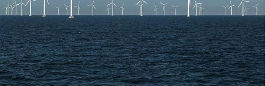
Nysted windfarm, RØsand
1. Offshore windpower.
1.1 Introduction.
• Generating electricity from wind.
• It can help to reduce energy imports, air pollution and
  greenhouse gases.
• Climate change and energy security.
• Main advantages of the offshore versus onshore windfarms:
    – Stronger wind speeds are available offshore compared to on land.
    – Unlike wind over the continent, offshore breezes can be stronger in
      the afternoon, matching the time when people are using the most
      electricity.
    – Offshore turbines can also be located close to the power‐hungry
      populations along the coasts, eliminating the need for new overland
      transmission lines.
•   As of 2013, the 630 MW London Array is the largest offshore
    windfarm in the world.
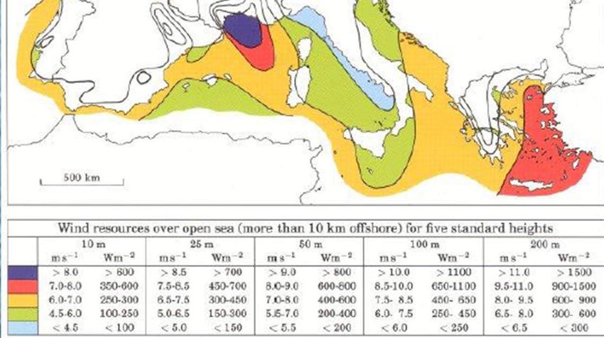
Offshore wind resources

1.2 Offshore wind market.

• In 1991:
   – First offshore windfarm inagurated, Vindeby.
   – 2.5km off the Danish coast.
   – 450 kW turbines for a total capacity of 5MW.
• In 2001 :
   – 50.5MW offshore capacity installed.
   – 1% of the total new European annual wind capacity.
• Offshore energy market in the EU in 2011.
   –   Total installed capacity of 4GW.
   –   0.4% of total EU electricity demand.
   –   Annual installations of 1GW.
   –   Avoiding 9.9 Mt of CO2 annually.
   –   Total electricity production of 148 TWh.
   –   Annual investments in wind turbines of €2.8billion.
• Offshore energy market in the EU in 2020.
   –   Total installed capacity of 40GW.
   –   4% of total EU electricity demand.
   –   Annual installations of 6.9GW.
   –   Avoiding 102Mt of CO2 annually.
   –   Total electricity production of 148 TWh.
   –   Annual investments in wind turbines of €10.4billion.
   –   Cumulative investments of €65.9 billion from 2011 to 2020.
• Total offshore wind power capacity is expected to reach a
  total of 75 GW worldwide by 2020.
• Offshore energy market in the EU in 2030.
   –   Total installed capacity of 150GW.
   –   14% of total EU electricity demand.
   –   Annual installations of 13.7GW.
   –   Avoiding 315Mt of CO2 in 2030.
   –   Total electricity production of 148 TWh.
   –   Annual investments in wind turbines of €17billion.
   –   Cumulative investments of €145.2 billion from 2021 to 2030.
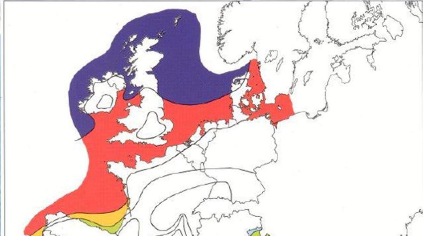
• By 2020, total amount of 462,000 people employed in the
  wind energy sector (169,500 in the offshore sector).
• By 2030, total amount of 480,000 people employed in the
  wind energy sector (300,000 in the offshore sector).
• Location of the total capacity:
   – 65% in the North sea.
   – 16% in the Baltic sea.
   – 19% in the Atlantic sea.
• No offshore windfarms in the Mediterranean sea. The water is
  deep and current commercial substructures are limited to (40‐
  50)m maximum depths.
World’s largest offshore wind farms
Share of new installed capacity in Europe 2010.
1.3 Offshore development trends.
•
2. Structures and foundations.
• Ground structures.
  – Monopile structures, depth < 25m.
  – Gravity‐based structures, depth < 30m.
  – Space frame structures, 20m < depth < 80m.
     • Jacket/Lattice structures.
     • Tripile structures.
     • Tripod structures.
• Floating designs, depth >50m.
  – Spare floater.
  – Tension leg platform.
  – Spar floater.
• Europe’s grid connected offshore wind turbines:
– Majority of wind farms in operation are monopile foundations:
• Water depth < (20‐25)m.
• Simple to produce.
• Easier to install.
• Less costly.
– Gravity based substructures.
– Small number (jackets, tripods and tripiles).
– Floating substructures (only two).
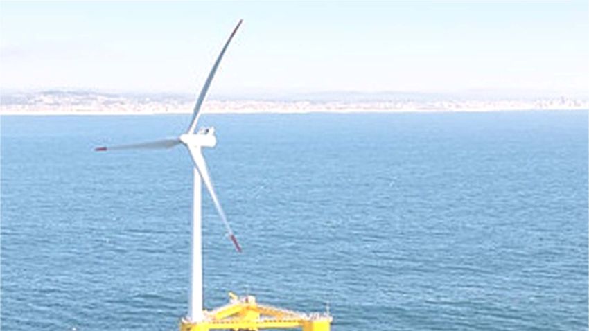
• Hywind, 2.3 MW turbine, Norway.
• Windfloat, 2 MW turbine, PortugalMonopile structures.
• Main features.
•   Single cylindrical steel tube embedded into the seabed.
•   The tower is supported by the monopile.
•   The monopile continues down into the seabed.
•   It is well suited for sites with water depth 0‐30m and it becomes less stable in
    deeper waters.

• Monopile variations.
•   Drilled monopile.
     – Steel monopile fixed with concrete in a deep hole drilled in the seabed rock.
     – It keeps the weight of the foundation relatively low.
•   Drilled concrete monopile.
     – Prefabricated concrete monopiles.
     – Uses concrete as base material.
Horns Rev wind farm, 80 turbines
generating 160 MW.Gravity support structures.
• Main features.
•   Concrete based structure.
•   Ballast required to anchor the foundation : sand, iron ore or rock.
•   Central steel or concrete shaft for transition to the wind turbine tower.
•   The structure requires: flat base and a some form for scour protection.
•   No tensile loads between the bottom of the support structure and the seabed.
    Sufficient dead loads so that the structure maintains its stability by means of its
    own gravity.
•   Constructed in building yards and transported to site.
•   Competitive when the environmental loads are relatively modest.
•   Using cylindrical or conical reinforced concrete caissons.
•   Water depth up to 30m.

• Examples.
•   Rødsand 2 (Denmark).
•   Vindeby (Denmark). It was the first offshore windfarm in the world.
•   Kårehamn.
Variations of gravity foundations. • Crane free gravity base (seatower). • Gravitas Gravity Base (Arup/Costain/Hochtief). • GBF gravity base. • Consortia of Skanska, Smit Marine Projects and Grontmij. • Vici Ventus Concrete Gravity Foundation (CGF). • STRABAG gravity base.
Crane free gravity base (seatower).

•   The foundation will be installed using only regular towing vessels.
•   More cost‐efficient, quicker to install and less risky than current methods
    that use steel foundation designs.
Gravitas Gravity Base (Arup/Costain/Hochtief).
• It can be installed in deeper waters with a self‐installation system.
• No need for specialist marine equipment.
• Reinforced concrete, non‐piled, ballasted gravity structure.
• Caters for water depths up to 60m.
• Suits larger turbine sizes up to an anticipated 8MW.
• The need for seabed preparation is minimized by acommodating existing
seabed slopes and surface sediments.
• Designs can be standardised across individual or multiple sites to enable
cost optimisation.
• Offers like cycle carbon footprint benefist through material selection.
• The construction takes place onshore and does not require deep water
(fast).
• During the installation, the foundations are self‐buoyant.Gravitas Gravity Base (Arup/Costain/Hochtief).
GBF Gravity Base (Vinci Construction UK/Freyssinet
International).
•   It is suitable for :
     – A large range of water depths (20‐55)m.
     – Many sea bed soil conditions.
     – Turbine sizes of (3‐10)MW.
•   Construction of the foundation, installation and pre‐testing of the tower
    and turbine takes place onshore.
•   Transport and installation using a Transport and Installation Barge (TIB).
•   Installation is quick.
•   Low maintenance.
Consortia of Skanska, Smit Marine Projects and
Grontmij.
• It is based on a caisson structure.
• Flexible and scalable to suit multiple sites and metocean conditions,
water depth up to 60m and different turbine loads.
• Long lifespan, 50 years, with low maintenance requirements.
• Self‐buoyant structure, no need for specialist vessels.
• No access required onto the foundation during the tow or water ballasting
operations.
• Turbine loads carried by the central shaft giving flexibility.
• Environmental benefits.
• Water ballast is required after installation to resist storms.
• The decommisioning process is straightforward as the foundation
structure is to be re‐floated.Vici Ventus Concrete Gravity Foundation (CGF).
Main features:
•Water depthVici Ventus Concrete Gravity Foundation (CGF). • Structure: – Self‐floating and stable structure with a buoyant shaft. – The turbine is towed to site . – Installation by ballasting. – Seabed preparation and offshore crane vessels are not required. – The installation has a short duration. – Maintenance is practically non‐existent. – Removal by reverse installation.
STRABAG gravity base.
STRABAG gravity base.

Main features:
•   Almost independent from the effects of weather and rough seas.
•   STRABAG terminals are quays with industrial plants.
•   They are located in logistically ideal areas.
•   Gravity base foundations are produced using pre‐stressed concrete.
•   Wind turbines are fully assembled.
•   Pre‐assembly can be complete onshore.
•   It can be used in water depths to 50m.
•   No pile‐driving, small footprint.
•   It minimises damage to ships in collision.
•   It can be completely disassembled.
•Space frame structures.
  – They are likely to be considered for deeper
    locations.
  – These structures transmit forces to the
    foundations in the seabed minimising the ratio of
    mass to stiffness.
Jacket / lattice structures.
• Advantages.
•   Loads transferred to the members in axial direction.
•   Large base of the jacket structure offers large resistance to overturning.
•   Large plan area through the majority of the structure, the steel is further from
    centre of the axis. Material savings.
•   Wave loads are lower in comparison to monopiles.
•   Fabrication expertise widely available.

• Disadvantage.
•   High initial construction and maintenance costs.

• Installation.
•   The jacket strutures are attached into the seabed through piles.
•   Methods: pre‐piling and post‐piling.
Tripile structure. • Three‐legged jacked structure. • In the lower section, it is connected to a monopile in the upper part of the water column. • The length of the piles vary from 65‐90m long and up to 3m in diameter. • The water depth ranges from 25‐40m.
Tripod structures.
• Main features.
•   Lightweight three‐legged structure made of cylindrical steel tubes.
•   The three piles are driven (10‐20)m into the seabed.
•   The piles are relatively small, (2‐3)m in a diameter.
•   The tripod foundation has good stability.
•   Distance between piles is from 20 to 40 m.
•   No suitable at water depth less than 6‐7m.
•   Foundation anchored to the seabed using a 0.9‐m diameter steel pile.

• Advantages.
•   Suitability for greater water depths.
•   Minimum of preparation at the site before installation.
Floating design structures.
• Spar buoy:
  – Very large cylindrical buoy.
  – Stability using ballast.
• Tension leg platform.
  – Buoyant structure is semi submerged.
• Jacket.
  – Semi‐submerged structure added to reach the
    necessary stability.
Spar structure Tensioned‐leg platform
Jacket structure
3. Turbines.
3.1 Aerodynamics of an airfoil.
   – Rotor blades, airfoil cross section.
   – Lift and drag forces as a result of pressure distribution and
     some friction.
   – Angle of attack, α.
   – Associated force resultants.
3.2 Aerodynamics forces on a rotating blade.
– The wind load is governed by:
• Relative wind speed.
• Relative angle of attack.
– The blade tangential velocity will create an apparent wind
velocity, same magnitude, opposite direction.
– Lift and drag forces form the total force resultant.
Decomposed into a tangential and axial force component.3.2 Driving aerodynamic torque. The tangential forces act with a certain arm about the rotational axis (in the rotor plane) creating the driving torque of the turbine.
Offshore wind turbine
Key sub‐components.

•   Towers.
•   Blades.
•   Drive train components.
•   Castings and forgings.
• Towers:
  – Wide selection of tower manofacturing facilities in
    Europe.
  – Manofacturing facilities for large diameters turbines in
    (5‐7)MW are more limited.
  – Additional coastal tower manofacturing facilities will
    be required in the coming decade.
• Blades:
  – Longer blades bring additional manofacturing and
    logistical requirements.
  – They are likely to limit additional supply chain capacity
    to coastal locations.
• Drive train components: – Gearboxes. – Large bearings. – Generators. • Castings: – Gearboxes. – Large bearings. – Generators. • Forgings: – Bearing/gear rings.
4. Vessels.
• Suitable vessels are required for transportation
  and to perform the various activities:
  development, construction, operation,
  decommisioning.
• Site development (surveys):
   – For the Environmental Impact Assesment.
   – Geophysical.
   – Geotechnical (stable platform from where to take
     boreholes examples).
   – Installation vessels such as the jack‐up types.
• Site construction:
– Greater demands are made on vessel types.
• Ship performance.
• Cost.
• Lift capacity.
• Precision when lifting.
• Vessel dimensions.
• Meteocen conditions.
• Technical risk.
• Commercial availability.
• Site operations.
– Crane vessels for performing turbine repairs.
– Crafts for transport technicians to and from site to
O&M purposes.• Site operations:
– “floatels” or “ motherships” for projects further than 50km
from port.
– Crews live aboard large floating vessels located in the
vicinity of the windfarm.
– Sufficient deck space and stability to mount heave‐
compensated access systems.
– Time available for plant maintenance can be maximised:
• Reducing transit time.
• Enabling access in rougher sea conditions.
• Site decommisioning:
– Similar vessels to those used for installing wind turbines will
be required for their removal during decommissioning or
repowering of offshore wind farm sites.• Installation vessel types:
– Jack‐up vessels.
• Capable of most roles on windfarms sites.
• Early windfarms used jack up vessels for virtually every task. It
was more economical to use one versatile vessel for all task as
windfarms were smaller.
• At larger future sites, greater specialisation with suite‐
optimised vessels.
• Stable base provided by a jack‐up. Ideal for installing the
nacelles and blades for turbines (the most precise lifts
required on a project).
• Small number of existing vessels with longer legs will be joined
by new build vessels with the capacity to carry out the (5‐
7)MW class turbine in waters from 30m to 45m deep.
• More vessels are needed for operating in areas with
depth>45m.Jack‐up vessel
Leg-stability crane vessels.

•   Only two have
    entered the
    windfarm
    installation fleet.

•   Ideal to install wind
    turbines in the
    shallower sites of
    the early windfarms.
Heavy lift cargo vessels.
• Cargo vessels deliver
loads rapidly and
cheaply by fitting
heavy cranes to the
vessel.
• They can collect and
deliver cargo from
ports where there is
not enough capacity.Leg-stability crane vessels.
• Only two have
entered the
windfarm
installation fleet.
• Ideal to install wind
turbines in the
shallower sites of
the early windfarms.Semi-submersible heavy lift vessel.
• Developedd by the
oil&gas industry.
• The hull can be
floaded increasing the
deadweight of the
craft.
• This ballasting
operation dramatically
lowers the peiod of
roll of the craft.
• The vessel is
motionless in the
water.
• High stabilityShearleg cranebarge
• Very heavy‐lift
configuration of a dumb
barge.
• The lifting frame is
permanently attached to
the deck.
• Designed for heavy‐
lifting in sheltered
waters.
• They can transit in seas
with Hs>1m and carry
out lifting operations in
seas with 0.5mFloating dumb barge with crane
• Land‐based crane on
to a dumb barge.
• Unsuitable for the
role of principal
installation vessel.
• It can be used for a
multitude of small
roles on any
offshore
construction site or
working as a feeder
vessel.5. Installation. 5.1 Foundation installation. • Most of the deep offshore designs can be assembled onshore and then towed to sea. No need to use vessels, reducing installation costs. • Self‐installing and port assembled systems must be developed. • Handling, installing mooring lines and anchors are the main installation challenge.
Installation of jackets.
Installation of jackets.
Installation of monopile foundations.
Installation of gravity foundations.
Installation of gravity foundations.
Installation of tripile foundations.
Installation of tripod.
5.2 Turbine installation.
5.2 Turbine installation.
6. The economic of deep offshore projects.
• According to the US Energy Information Agency, it is the most
  expensive energy generating technology for large scale deployment.
•   58,000 people employed.
• Installation costs are important costs.
• Cost reduction is one of the main challenges.
• Floating offshore substructures costs are mainly the cost:
     – Platform.
     – Anchoring system.
• These costs are similar to those for fixed‐bottom solutions in deep
  waters.
• Design and installation costs in floating offshore substructures are
  cheaper.
• Floating offshore designs are expected to produce more energy
  (bigger turbines can be accommodated).
• Unfortunately, few countries have specific laws for windfarms. • Most countries use existing marine planning laws which can delay projects considerably. • Floating wind substructures have a lot in common with oil&gas floating substructures. Knowledge from oil&gas industry can be used for floating windfarms.
7. Ports.
• It is a significant opportunity for ports to counter‐
  balance the downturn hitting traditional
  activities.
• Supply       chain and port infraestructure
  requirements are similar for all types of offshore
  wind substructures.
• Ports must allow for increased throughput.
  Enough space to accommodate installation and
  component storage.
• Two main types of ports:
   – Manofactuing ports:
   – Mobilisation ports:
• Manofactuing ports:
   • The manofacturing facility is closely located.
   • The components are exported directly to the offshore site.

• Mobilisation ports:
   • The components are received ready and transported to the
     offshore site.
   • Economically advantageous when the offshore wind site is
     located at some distance from the manofacturing hubs but not
     with significant enough activity to justify long‐lasting local
     supply chain development.
   • It will only take on the construction requirements.
• Transportation of technicians from port to site:
– 12‐passenger workboats have tradionally been used.
– Larger vessels and helicopters are used as projects
move further offshore. Port‐based support structure is
required.
• Technical requirements from the vessels:
– Vessel beam (width).
– Draft laden and un‐laden.
– Overall length of the vessel.
– Overhead clearance required.
• Technical requirements from the components:
– Dimensions.
– Weight.Port requirements:
• Quayside:
• Long enough to accommodate 2‐3 vessels. 300m < length < 1000m.
• Bear weights of 15‐20 tonnes/m2.
• Allow jacking up right next to the quayside for using boat’s own crane and the
crane on the harbour.
• Avoid the dents made by the jack’s legs weakening its structure.
• Gantry crane of 1,000 t must be used.
• Roll‐on and roll‐off capability and trailer options should be available.
• No restrictions to vessels accessing the harbour.
• Minimum draught of 12.5m for multipurpose vessels supplying wind
turbine elements.
• The waterway should allow the transportation of a full rotor 150‐
200m in diameter.
• Storage area between 25ha to 50 ha.
• Full time access for service vessels and service helicopters. Relevant in
cold areas where ice‐breaking vessels are required.Port logistics
Scope allocation possibilities.
BIBLIOGRAPHY
•   Marine lecture 1. Offshore wind turbines installation. August 2012.
    University of Stavanger.
•   Wind in our Sails. Nov 2011. Report by the European Wind Energy
    Association.
•   Deep water. The next step for offshore wind energy. July 2013. Report by
    the European Wind Energy Association.
•   Offshore structure design and construction. Ships and offshore structures
    journal. Frieze, P. A.
•   Support Structures for Offshore Wind Turbines. 4C offshore.
•   Wind turbines: Fundamentals of aerodynamic loads. Wind engineering.
    Jakobsen, J. B.
You can also read