Crash analysis of sandwich composite electric microbus
←
→
Page content transcription
If your browser does not render page correctly, please read the page content below

IOP Conference Series: Materials Science and Engineering

PAPER • OPEN ACCESS

Crash analysis of sandwich composite electric microbus
To cite this article: P. Jongpradist et al 2021 IOP Conf. Ser.: Mater. Sci. Eng. 1137 012048

View the article online for updates and enhancements.

 This content was downloaded from IP address 46.4.80.155 on 11/09/2021 at 02:05
The 11th International Conference on Mechanical Engineering (TSME-ICOME 2020) IOP Publishing
IOP Conf. Series: Materials Science and Engineering 1137 (2021) 012048 doi:10.1088/1757-899X/1137/1/012048

Crash analysis of sandwich composite electric microbus

 P. Jongpradist1,*, S. Limpanawisut1, A. Siritana1, P. Saardying1, N. Saingam1,
 P. Tangthamsathit1, P. Chanpaibool1
 1
 Department of Mechanical Engineering, Faculty of Engineering,
 King Mongkut’s University of Technology Thonburi, 126 Pracha Uthit Rd.,
 Bang Mod, Thung Khru, Bangkok, Thailand 10140

 * Corresponding Author: pattaramon.jon@mail.kmutt.ac.th

 Abstract
 Sandwich composite is ideal for lightweight monocoque structure owing to not only its
 superiority in strength-to-weight ratio and specific flexural properties but also its
 manufacturability to any desired complex shape. In this work, an optimum lightweight
 design of monocoque composite sandwich-structure microbus subjected to bending and
 torsion stiffness criteria and natural frequency constraints is further investigated under
 crash conditions through finite element analysis. A composite sandwich panel made of
 5.4-mm woven glass fabric-epoxy face sheets and 50-mm rigid polyurethane foam core
 is tested under low-velocity impact with a hemisphere headed impactor following
 ASTM D7136 to characterize the failure characteristics. An enhanced composite
 damage material model so-called MAT54 in LS-DYNA with damage progression in
 each lamina utilizing strength-based Chang-Chang criteria is implemented with various
 formulations to validate and compare for their efficiency and accuracy under impact
 test. The reduced-integration Balytschko-Tsay shell element with 5 through-thickness
 integration points is applied to the monocoque composite microbus model.
 The structural crashworthiness under the frontal crash of the bus at 20, 40 and 50 km/h
 to a rigid wall barrier is examined. The front structure absorbs the most frontal impact
 energy up to 60% and shows severe damage when the crash velocity is 40 km/h or
 higher. For the bus impact velocity of 50 km/h, the maximum deformation of the bus
 front is 809 mm resulting in the intrusion of the structure into the specified driver
 survival space. Design improvement of the sandwich structure should be further
 explored to enhance its energy absorption and safety of the bus under crash events.

 Keywords: Crash simulation, Sandwich structure, Composite material, Microbus

1. Introduction
An electric vehicle is a green alternative to traditional internal combustion engine vehicle that benefits
in reducing emissions of greenhouse gas and air pollution contributing to climate change and smog. One
of the key challenges in designing electric vehicles lies in lightweight design and energy efficiency.
However, the safety of the vehicle structures must not be compromised. Sandwich composite is ideal
for lightweight monocoque structure owing to its superiority in strength-to-weight ratio and specific
flexural properties as well as its manufacturability to any desired complex shape. Many researchers have
been focused on developing composite automotive parts to enhance vehicle strength and

 Content from this work may be used under the terms of the Creative Commons Attribution 3.0 licence. Any further distribution
 of this work must maintain attribution to the author(s) and the title of the work, journal citation and DOI.
Published under licence by IOP Publishing Ltd 1
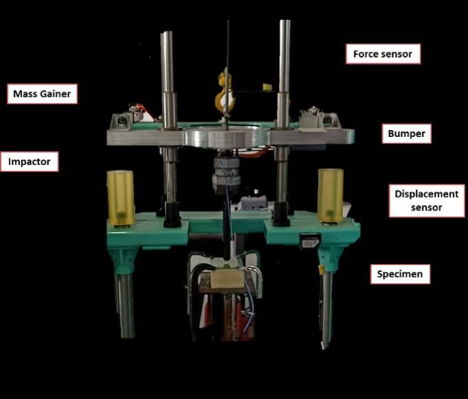
The 11th International Conference on Mechanical Engineering (TSME-ICOME 2020) IOP Publishing
IOP Conf. Series: Materials Science and Engineering 1137 (2021) 012048 doi:10.1088/1757-899X/1137/1/012048

crashworthiness. Kang et al. [1] appended carbon composite roll bar components to the bus structure to
improve safety under rollover in which the maximum deformation of the bus structure could be reduced
by 40% at the end of the collision. Ko et al. [2] designed a composite bus structure made of glass
fabric/epoxy with stainless steel inserts as the bus frame. Safety of the bus under frontal crash to a rigid
wall at a speed of 60 km/h and rollover according to ECE-R66 standard were verified via finite element
analysis using LS-DYNA. Several studies [3-5] designed lightweight superstructure for the bus roof
strength based on ECE-R66 rollover test. It was found that pillar strength highly affects the bus
crashworthiness under rollover accident [6-7].
 Recently, Kunakorn-ong et al. [8] designed a lightweight monocoque composite sandwich-structure
microbus based on bending and torsion stiffness criteria and natural frequency constraints. The
monocoque design proves to considerably reduce the body weight while the bus stiffness under working
conditions are reassured. The current study further investigates the performance of the bus structure
under full frontal crash conditions by using finite element analysis using LS-DYNA. Recommendations
on safety improvement are also provided.

2. Modelling and Validation

2.1 Validation of material models through an impact drop test
The material models defined in LS-DYNA are verified following ASTM D7136 Measuring the Damage
Resistance of a Fiber-Reinforced Polymer Matrix Composite to a Drop-Weight Impact Event [10]. This
test method determines the damage resistance by using a drop weight machine with a hemispherical
striker tip as displayed in Figure 1a. A sandwich structure composes of 4 plies of 0/90 G600 glass fiber
fabric and 5 plies of ±45 G600 glass fiber fabric for each skin and 50-mm H100 foam core. Four
composite specimens made by vacuum infusion process are tested under impact energy of 100 J, 150 J,
and 200 J. The impactor mass is 10 kg and the impact velocity ranges are between 3.1 and 5.4 m/s.
Damages of the specimens for different impact energy are shown in Figure 1b. It can be seen that the
damage area increases as the impact energy increases. Fiber fracture and delamination are observed in
all specimens and permanent foam deformations occur without perforation of the composite panels.
 The impact test scenarios are simulated in LS-DYNA by using a mesh size of 2 mm. For explicit
dynamic simulation using plate and shell elements in LS-DYNA, the critical time step is automatically
determined by the wave propagation velocity for membrane deformations governed by the size of the
smallest element. The MAT024 Piecewise linear plasticity is assigned to H100 foam core while the
composite material model is assigned as MAT054 Enhanced composite damage with Chang-Chang
strength-based damage criteria. The 2-way fiber behavior option is triggered to account for the properties
of woven fabric. Thus, the failure criteria e in material coordinates a- and b-directions (corresponding
to the fiber direction of 0 and 90 degrees) are given as follows:

 (a) 100 J 150 J
 (b) 200 J

 Figure 1. (a) Impact testing machine and test set-up (b) Specimen damages after impact test

 2
The 11th International Conference on Mechanical Engineering (TSME-ICOME 2020) IOP Publishing
IOP Conf. Series: Materials Science and Engineering 1137 (2021) 012048 doi:10.1088/1757-899X/1137/1/012048

 for the tensile fiber mode in both directions,
 2 ≥0 failed
 > 0, 2 = ( ) + ( )− 1{
 0, 2 =( ) + ( )−1{
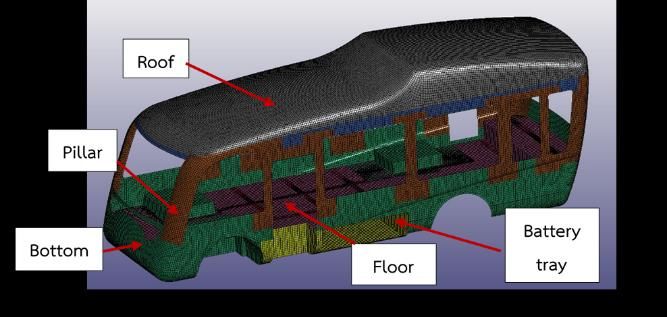
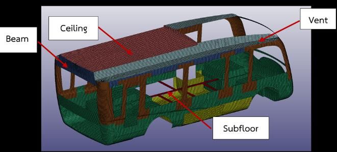
The 11th International Conference on Mechanical Engineering (TSME-ICOME 2020) IOP Publishing
IOP Conf. Series: Materials Science and Engineering 1137 (2021) 012048 doi:10.1088/1757-899X/1137/1/012048

 Figure 2. Simulated results under impact drop and CPU times using various model formulations

 Table 1 illustrates the force-displacement curves obtained from numerical simulation are compared
with the maximum forces recorded from the experiments. For all impact energy of interest, the sandwich
structures are damaged with permanent deformations after the impactor rebound. The higher the impact
energy, the higher the impact force and permanent deformation. It is also noticed that the maximum
forces from impact test are somewhat less than that obtained from FEA whereas the predicted
displacements at the maximum force are comparable. Results discrepancies are more apparent when the
impact velocity is higher. The maximum force obtained from the experiment of 200-J impact seems to
be rather lower than the expected value. This could be owing to inhomogeneous material properties of
the composite laminate which cannot be captured in the simulation results. The results can be further
investigated via reliability analysis to account for this contribution.

 Table 1. Experimental and simulation result for forces and displacement under an impact drop test.

 Test Impact Maximum force Maximum displacement
 no. energy (J) Exp (kN) Sim (kN) Error Exp (mm) Sim (mm) Error
 1 100 31.1 35.6 14.4% 6.8 7.5 9.8%
 2 150 43.6 47.0 7.8% 8.4 8.5 1.6%
 3 200 44.3 55.2 24.4% 8.9 9.4 6.4%

2.2 Baseline design
The sandwich composite microbus used in the current study is adopted from Kunakorn-ong [8] as
illustrated in Figure 3. The bus consists of nine components distinguished by their functions including
the bottom, floor, roof, beam, ceiling, pillar, battery tray, subfloor, and vent. The bus is 2.4 meters wide,
7.8 meters long and 3.2 meters height with 24 passenger seats. To correctly compute the dynamic
behavior of the bus under crash events, the mass of other important components is uniformly distributed
in the FE model at their corresponding locations. The mass elements for axle systems, windows and
doors of 1892 kg are assigned to the bottom component. The driver and 24-passenger load and seats of
2282 kg are given to the floor. The 1536-kg battery is applied to the battery tray. The total body weight
of the baseline bus 7,610 kg.
 In this paper, the FE simulation is performed by using LS-DYNA. The shell elements of size 30 mm2
were implemented to all components of the bus model. The total numbers of elements in the baseline
model are 104,829 elements. The sandwich structure is composed of H100 foam core and E-glass/epoxy
faces with their thicknesses and ply orientations as listed in Table 2 with the color code explanation in
Table 3. The glass fiber fabric with a surface density of 400 g/m 2 (G400) and 600 g/m2 (G600) was
mainly selected for the design of structure due to its lightweight and high specific stiffness, strength,
and toughness except that the plain-weave carbon fiber fabric with a surface density of 200 g/m 2 (C200)
was implemented at the battery tray where much higher bending stiffness of the component was required

 4
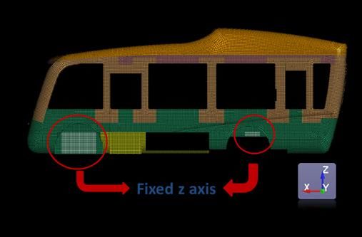
The 11th International Conference on Mechanical Engineering (TSME-ICOME 2020) IOP Publishing
IOP Conf. Series: Materials Science and Engineering 1137 (2021) 012048 doi:10.1088/1757-899X/1137/1/012048

 Figure 3. Components of composite microbus.

 Table 2. Material layup for composite microbus components.

 Component Laminate layup Thickness (mm) weight (kg)

 Bottom 61.2 524
 Vent 38.8 130
 Battery Tray 69.2 270
 Pillar 55.2 204
 Floor 47.2 232
 Roof 4 125
 Ceiling 70 264
 Beam 51.2 44
 Subfloor 6.6 5

 Table 3. Material, ply thickness and fiber orientation for color codes used in Table 1.

 Ply thickness Fiber direction Fiber direction
 Material Color code Color code
 (mm) (degree) (degree)
 G400 0.4 0/90 ±45
 G600 0.4 0/90 ±45
 C200 0.4 0/90 ±45
 H100 (core) 5 -

to support the weight of the battery packs. Each layer of fabric has a nominal thickness of 0.4 mm. The
zero-degree fiber directions for all components were assigned in the orientation along the horizontal axis
parallel to the floor in the plane of each the component panel. Mechanical material properties for the
composite faces and foam core are obtained from [8].

3. Frontal crash simulation
The bus structure under full frontal crash to a rigid wall barrier is simulated. The bus is constrained in
z-axis at the wheel locations and the initial velocities v at 20, 40 and 50 km/h are prescribed in +x-
direction (see Figure 4a). Automatic single surface contact interaction is assigned to all parts. The driver
survival space is measured according to the survival space in ECE-R29 [11] corresponding to the
reference point of the driver’s center of gravity. Therefore, the maximum deformation of the bus frontal
structure should not be greater than 600 mm after full-frontal crash. An example of bus deformation

 5
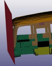
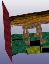
The 11th International Conference on Mechanical Engineering (TSME-ICOME 2020) IOP Publishing
IOP Conf. Series: Materials Science and Engineering 1137 (2021) 012048 doi:10.1088/1757-899X/1137/1/012048

behavior for the frontal crash with an initial velocity of 50 km/h is represented in Figure 4b. The bus
impacts the wall at the time = 29 ms and structural damage start occurring at 60 ms until the crash
finished at 160 ms.
 The energy absorption of each component under the initial impact velocity of 20, 40 and 50 km/h are
displayed and compared in Figure 5. The values indicated in the plot is the internal absorbed energy by
each component after the crash while the y-axis shows the percentage of energy absorption for each
part. For all crash velocities, most of the kinetic energy is transferred to the bottom and floor of the
microbus by which approximately 90% of crash energy are absorbed. The bottom component especially
the front panel absorbs more percentage of impact energy when the crash velocity increases.

 v = 20, 40, 50 km/h

 0 ms 50 ms 150 ms

Figure 4. (a) Boundary and initial conditions (b) Deformation behavior for a frontal crash at 50 km/h.

 100% 2.63 1.25 7.17
 10.3 41.8 60.9
 Percentage of absorbed energy

 90%
 80%
 166.6 234.7
 70% 53.3
 60%
 50%
 40%
 Bottom
 30% 271.1 418.0
 58.8 Floor
 20%
 Pillar
 10%
 Battery Tray
 0%
 20 km/h 40 km/h 50 km/h
 Impact velocity

 Figure 5. Percentage energy absorbed by each component under the frontal crash.
 900 2500
 800 40 km/h
 Deformation of bus front (mm)

 2000 50 km/h
 Distance along bus height (mm)

 700
 600
 1500
 500
 400 1000
 300
 20 km/h
 200 40 km/h 500
 100 50 km/h

 0 0
 0 500 1000 1500 2000 2500 0 200 400 600 800 1000
 Distance along bus width (mm) Deformation of front pillar (mm)

 (a) (b)
 Figure 6. Deformations of (a) front panel and (b) right front pillar.

 6
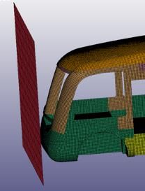
The 11th International Conference on Mechanical Engineering (TSME-ICOME 2020) IOP Publishing
IOP Conf. Series: Materials Science and Engineering 1137 (2021) 012048 doi:10.1088/1757-899X/1137/1/012048

 Figure 6 provides the deformations of the front panel at 400-mm height from the lower floor of the
bus and the deformations along with the right pillar’s height for different impact velocity. The
deformation of the frontal part at a slow impact velocity of 20 km/h is found to be less than 50 mm.
Nonetheless, damages in the compressive fiber mode are already detected at the outer ply of the
sandwich face in the front panel of the bus. At an impact velocity of 40 km/h, the front panel has
damaged in all failure modes with the largest damage in compressive fiber mode. However, the
deformations of the front panel and pillar are still less than the criteria for survival space. When the
crash speed reaches 50 km/h, the maximum deformation is found to be 809 mm in which the driver’s
survival space is intruded by 59 mm. This implies that the driver is not safe during the crash accident
and the front panel should be re-design to improve the bus crashworthiness under the frontal crash.

4. Conclusions
This study set out to present the method to simulate an impact drop test to a sandwich structure with a
different number of integration points and shell element formulation. The use of highly computing-
efficient Balytschko-Tsay element with the minimum through-thickness integration points has proved
to provide comparable and reliable results with much more detailed elements. The simple model is thus
applied to crash analysis of a complex sandwich composite microbus. Most of the impact energy from
the frontal crash are found to dissipate via the bottom components through front panel’s deformation.
Consequently, the baseline bus model is not safe under the frontal crash. Overall, this study strengthens
the idea that the design of these two parts should be modified to increase the energy absorption of the
part to improve the crashworthiness of the structure under full-front collision.

References
[1] Kang K Chun H Na W Park J Lee J Hwang I and Hong H 2011 Proc. the 18th International
 conference on composite materials (Jeju, Korea)
[2] Ko H Y Shin K B Jeon K W and Cho S H 2009 J. Mech. Sci. and Technol. 23(10) 2686-2693
[3] Gursel K T and Gursesli S 2010 Gazi Univ. J. Sci. 23(1) 71-79
[4] Liang C C and Le G N 2009 Int. J. Crashworthiness 14(6) 623-639
[5] Karlinski J Ptak M Dzialak P and Rusinski E 2014 Arch Civ. Mech. Eng. 14(1) 342-343
[6] Kongwat S Jongpradist P and Hasegawa H 2020 Int. J. Automot. Technol.
 21(4) 981-991
[7] Kunakron-ong P and Jongpradist P 2020 Int. J. Automot. Technol. 21(1) 215-25
[8] Kunakorn-ong P Ruangjirakit K Jongpradist P Aimmanee S and Laoonual Y 2020 Proc. Inst.
 Mech. Eng., Part C 3-1
[9] Sirisobrana P Ruangjirakit K Jongpradist P and Aimmanee S 2019 Proc. the 22nd International
 Conference on Composites Materials (Melbourne, Australia)
[10] ASTM D7136 Standard Test Method for Measuring the Damage Resistance of a Fiber-
 Reinforced Polymer Matrix Composite to a Drop-Weight Impact Event
[11] United Nations 2011 Economic Commission for Europe agreement regulation No.29: Uniform
 Provisions Concerning the Approval of Vehicles with regard to the Protection of the
 Occupants of the Cab of a Commercial Vehicle

 7
You can also read